Hardware:
The main controller used is the LCSC CW32F030C8T6 development board, which I got for 1 yuan during a promotion (LCSC's promotions are always very generous).
The key advantages of the CW32 in this project are:
Wide operating temperature range: -40~105℃;
Wide operating voltage: 1.65V~5.5V (STM32 only supports 3.3V systems);
Strong anti-interference: HBM ESD 8KV; All ESD reliability reaches the highest international standard level (STM32 ESD 2KV);
A key focus of this project – a better ADC: 12-bit high-speed ADC, achieving ±1.0LSB INL 11.3ENOB; Multiple Vref reference voltages... (STM32 only supports VDD=Vref);
Stable and reliable eFLASH technology. (Flash0 is pending).
The main characteristics of the CW32's ADC
require special attention in this project: 4 reference voltage sources. The content is based on the "CW32x030 User Manual."
The circuit is basically drawn 1:1 following the original project. For easier routing, the button I/O ports on the development board were changed from PB13, PB14, and PB15 to PC13, PC14, and PC15.
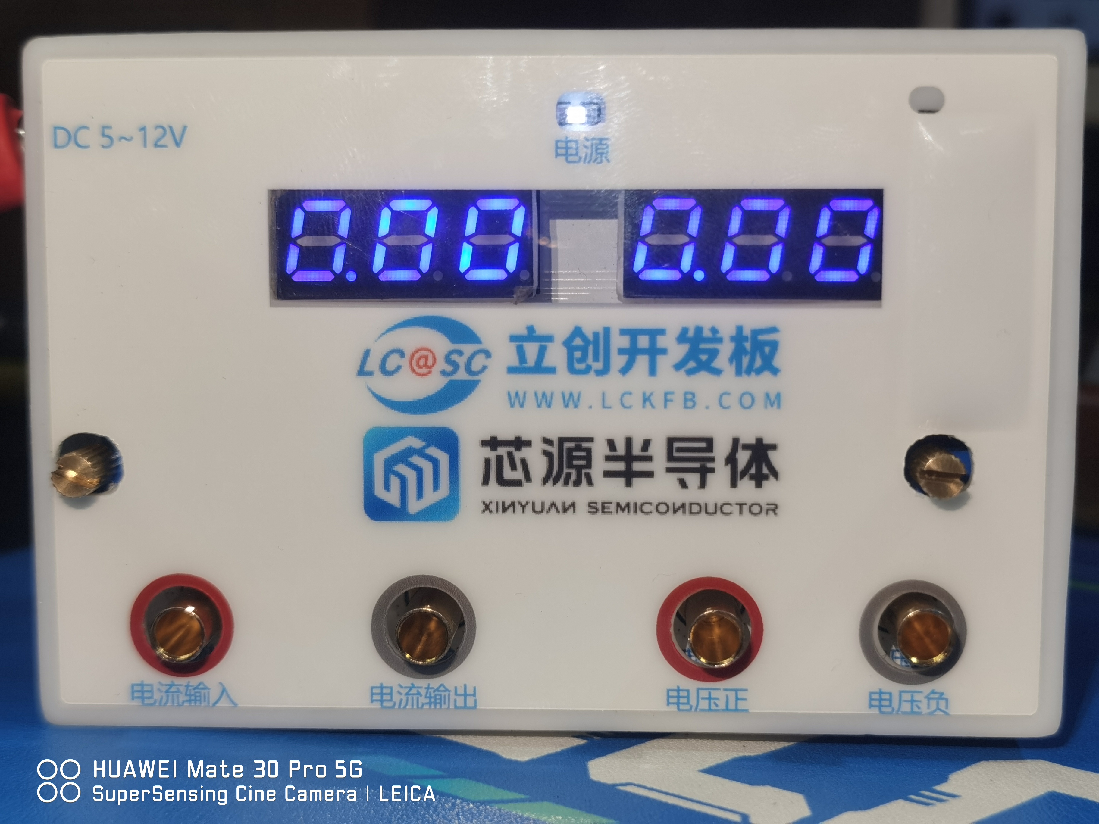
The original circuit used a 0.28mm common cathode seven-segment display, but I happened to have a common anode one on hand, so I used that instead. The code can be modified later.
Most other components were replaced with surface-mount components, as all the ones I had were surface-mount. Except for the 100mR sampling resistor, which requires a high-power resistor, 0805 resistors were sufficient for most other components.
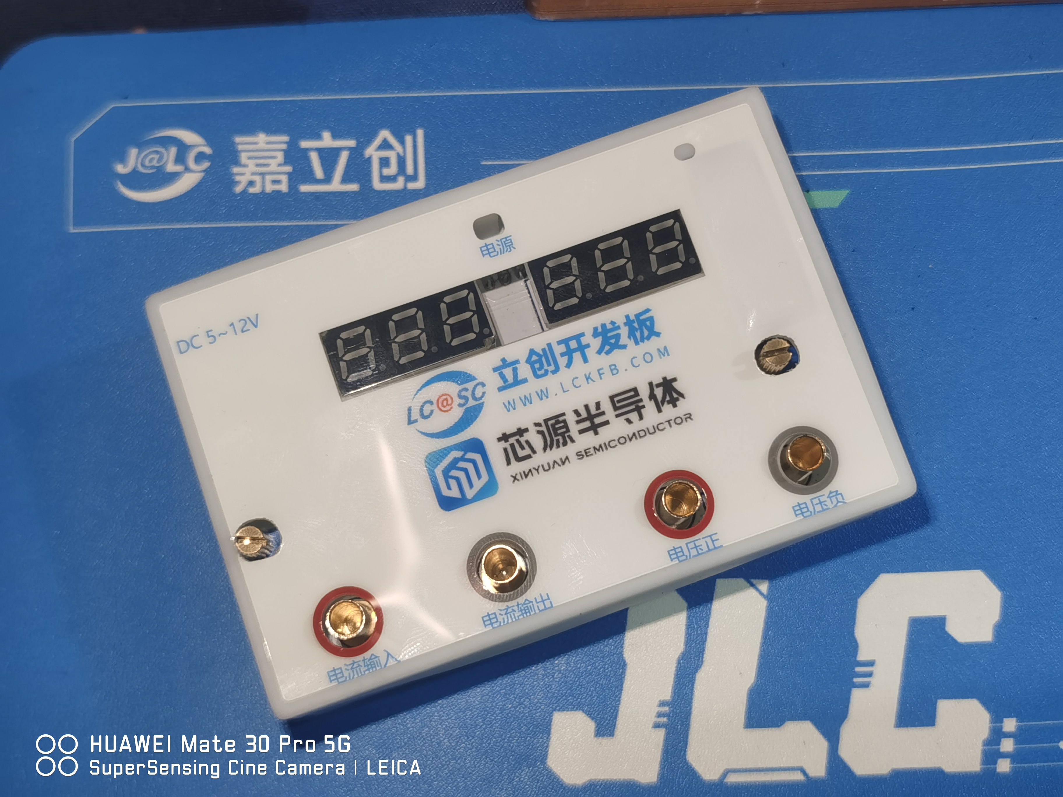
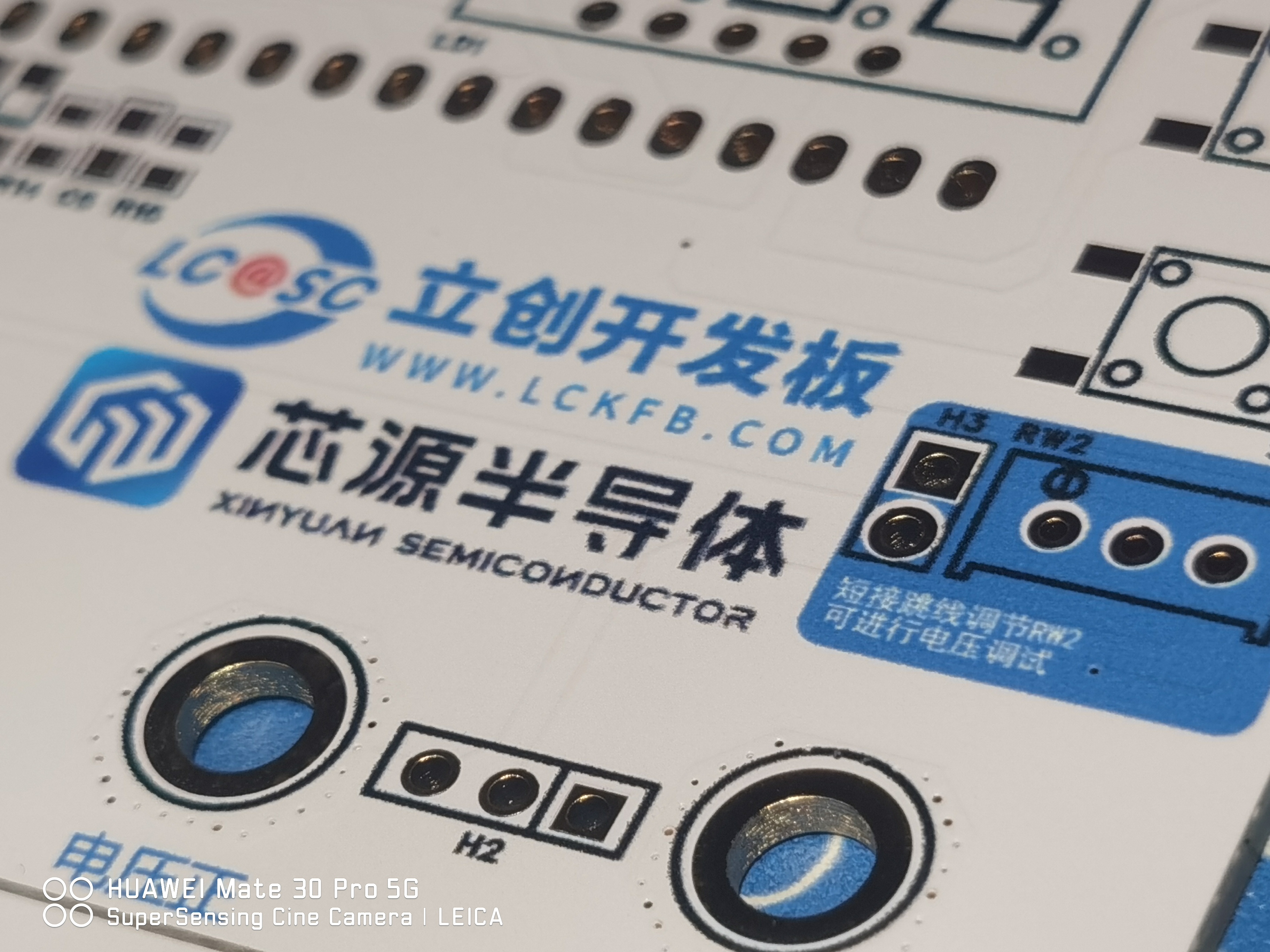
The PCB used LCSC's color silkscreen printing (a free coupon from the training camp), which produced excellent results. It didn't fade even with industrial board cleaning fluid, and the colors were very beautiful, with high resolution and precision. For the
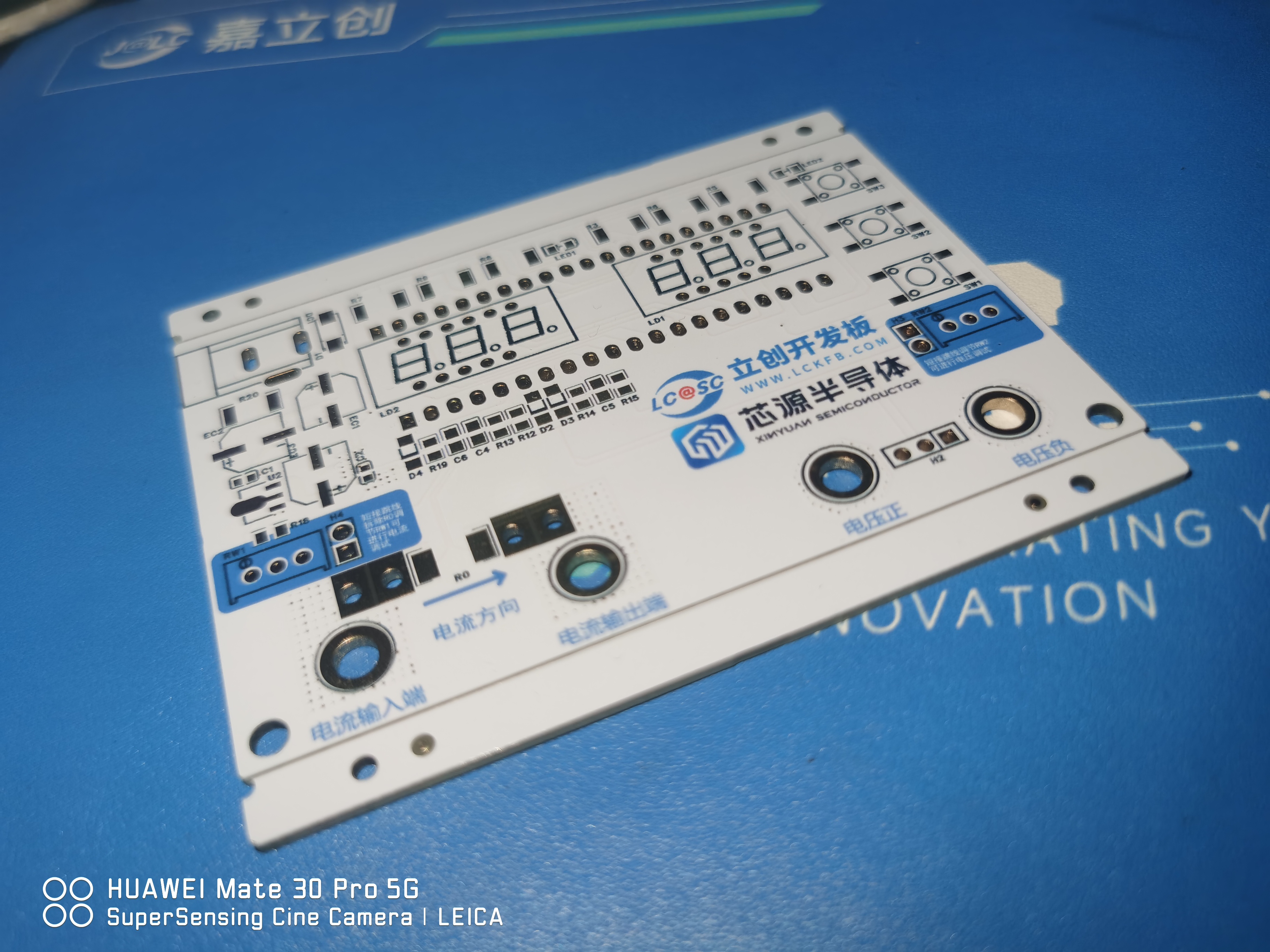
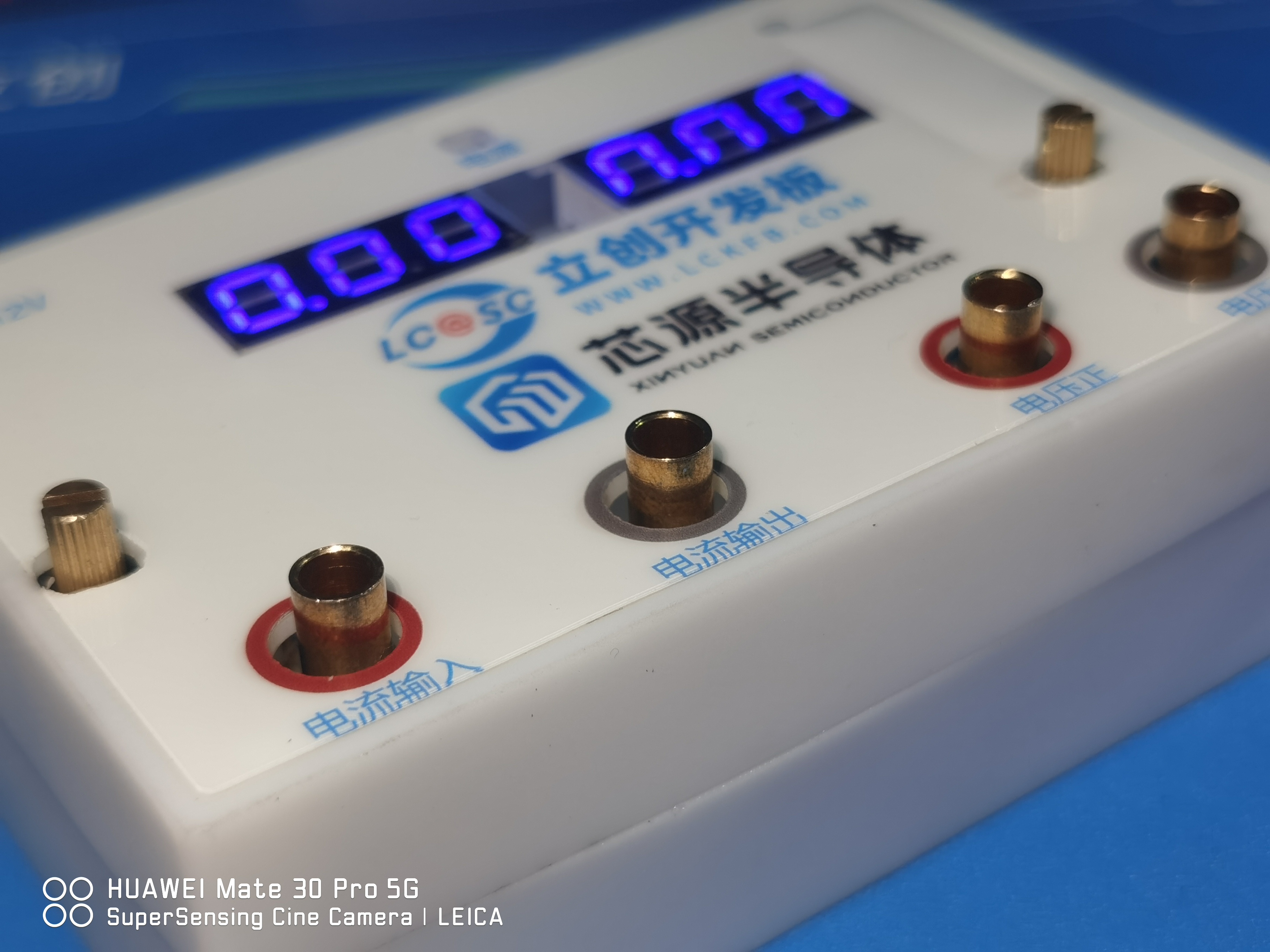
banana plug, I used a 4mm plug with an M3 thread, with a height similar to the multi-turn fine-tuning mechanism with a handle. This allowed me to design the casing with the height slightly lower than the fine-tuning height. The hole is slightly higher than the outer casing for easy insertion and removal. (This was my first time designing an outer casing. I found that 1.5mm was too thin and the printed result was distorted. Don't try this at home. The thickness should be at least 2mm.)
To reduce the size, the development board is placed on the reverse side, and the digital display is placed on the front of the development board to save space.
Program Download:
For firmware download, I used DAP_LINK, which is the Liangshanpai-compatible firmware. Just solder a header and it's ready to use. The wiring method is as follows.

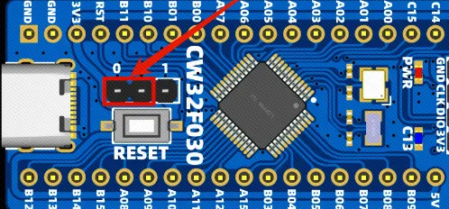
Even without the BOOT connection, you can download using the Liangshanpai downloader.
Keil settings are as follows

:
Software: I modified the LED and KEY I/O ports, as well as the digital tube display code, changing it to common anode. The specific code is as follows:
#include "Seg_Dis.h"
/ Common Cathode Digital Tube Encoding Table:
0x3f 0x06 0x5b 0x4f 0x66 0x6d 0x7d 0x07 0x7f 0x6f
0 1 2 3 4 5 6 7 8 9
0xbf 0x86 0xdb 0xcf 0xe6 0xed 0xfd 0x87 0xff 0xef
0. 1. 2. 3. 4. 5. 6. 7. 8. 9. /
/ Common anode digital tube encoding table:
0xc0 0xf9 0xa4 0xb0 0x99 0x92 0x82 0xf8 0x80 0x90
0 1 2 3 4 5 6 7 8 9
0x40 0x79 0x24 0x30 0x19 0x12 0x02 0x78 0x00 0x10
0. 1. 2. 3. 4. 5. 6. 7. 8. 9.
0x88 0x83 0xc6 0xa1 0x86 0x8e
A BCDEF
/
/ Replace the data in the array Seg_Table with the above common anode encoding table /
uint8_t Seg_Table[21] = { 0xc0,0xf9,0xa4,0xb0,0x99,0x92,0x82,0xf8,0x80,0x90,
0x40,0x79,0x24,0x30,0x19,0x12,0x02,0x78,0x00,0x10};// 0xF7:A.
uint8_t Seg_Reg[6] = {1,2,3,4,5,6};
/The configuration of the digital tube's IO port does not need to be changed/
void Seg_Init(void)
{
__RCC_GPIOA_CLK_ENABLE();//Turn on the clock of GPIOA__RCC_GPIOB_CLK_ENABLE
();
GPIO_InitTypeDef GPIO_InitStruct; //Configure GPIO
GPIO_InitStruct.Pins = GPIO_PIN_0 | GPIO_PIN_1|GPIO_PIN_2|GPIO_PIN_3 | GPIO_PIN_4|GPIO_PIN_5|GPIO_PIN_6 | GPIO_PIN_7|GPIO_PIN_8|GPIO_PIN_11|GPIO_PIN_12|GPIO_PIN_15; //PA00,E;PA04,G
GPIO_InitStruct.Mode = GPIO_MODE_OUTPUT_PP;
GPIO_InitStruct.IT = GPIO_IT_NONE;
GPIO_InitStruct.Speed = GPIO_SPEED_HIGH;
GPIO_Init(CW_GPIOA, &GPIO_InitStruct);
GPIO_InitStruct.Pins = GPIO_PIN_3 | GPIO_PIN_4;
GPIO_Init(CW_GPIOB, &GPIO_InitStruct);
}
This section remains unchanged.
void Seg_Dis(uint8_t Pos,uint8_t Num)
{
int i;
uint8_t Dis_Value;
Dis_Value = Seg_Table[Num];
for(i = 0; i < 8; i++)
{
switch(i)
{
case 0:
GPIO_WritePin(CW_GPIOA,GPIO_PIN_2,(Dis_Value >> i) & 0x01); //PA02,A
break;
case 1:
GPIO_WritePin(CW_GPIOA,GPIO_PIN_0,(Dis_Value >> i) & 0x01); //PA00,B
break;
case 2:
GPIO_WritePin(CW_GPIOA,GPIO_PIN_4,(Dis_Value >> i) & 0x01); //PA04,C
break;
case 3:
GPIO_WritePin(CW_GPIOA,GPIO_PIN_6,(Dis_Value >> i) & 0x01); //PA06,D
break;
case 4:
GPIO_WritePin(CW_GPIOA,GPIO_PIN_7,(Dis_Value >> i) & 0x01); //PA07,E
break;
case 5:
GPIO_WritePin(CW_GPIOA,GPIO_PIN_1,(Dis_Value >> i) & 0x01); //PA01,F
break;
case 6:
GPIO_WritePin(CW_GPIOA,GPIO_PIN_3,(Dis_Value >> i) & 0x01); //PA03,G
break;
case 7:
GPIO_WritePin(CW_GPIOA,GPIO_PIN_5,(Dis_Value >> i) & 0x01); //PA05,DP
break;
default:
break; /*The common terminal level here should all be changed to high level*/ switch(Pos) { case 0: GPIO_WritePin(CW_GPIOA,GPIO_PIN_8,GPIO_Pin_SET); //PA8,COM1
break
; case 1: GPIO_WritePin(CW_GPIOA,GPIO_PIN_11,GPIO_Pin_SET); //PA9,COM2 break; case 2: GPIO_WritePin(CW_GPIOA,GPIO_PIN_12,GPIO_Pin_SET); //PA10,COM3 break; case 3: GPIO_WritePin(CW_GPIOA,GPIO_PIN_15,
GPIO_Pin_SET); //PA11,COM4 break; case 4: GPIO_WritePin(CW_GPIOB,GPIO_PIN_3,GPIO_Pin_SET); //PA12,COM5 break; case 5: GPIO_WritePin(CW_GPIOB,GPIO_PIN_4,GPIO_Pin_SET); //PA15,COM6 break; default: break; } } /** @brief Close all common pins. Change all common pin levels to low. / void Close_Com(void) { GPIO_WritePin(CW_GPIOA,GPIO_PIN_8,GPIO_Pin_RESET);
GPIO_WritePin(CW_GPIOB,GPIO_PIN_3,GPIO_Pin_RESET);
GPIO_WritePin(CW_GPIOB,GPIO_PIN_4,GPIO_Pin_RESET);
GPIO_WritePin(CW_GPIOA,GPIO_PIN_11,GPIO_Pin_RESET);
GPIO_WritePin(CW_GPIOA,GPIO_PIN_12,GPIO_Pin_RESET);
GPIO_WritePin(CW_GPIOA,GPIO_PIN_15,GPIO_Pin_RESET);
}


 京公网安备 11010802033920号

 EPA189-225


