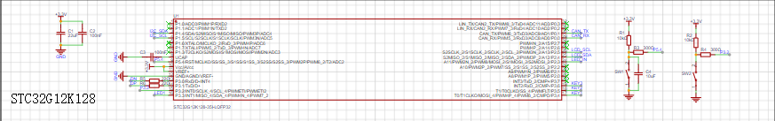
 is designed based on the STC32G series datasheet, using an internal crystal oscillator and hardware USB download
  uses the SY8088AAC, a low-noise DC-DC chip with a 1.5MHz switching frequency. According to the datasheet, it can provide a maximum current of 1A. However, this project does not require such a large current; it is only for testing the chip. The
 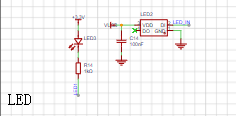 are unremarkable. The
 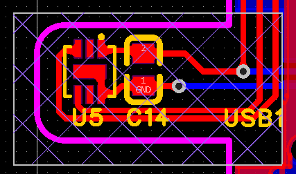 is a Zhongke Yinhexin GXHTC3 PIN-to-PIN compatible with Sensirui SHTC3, and is driven by hardware IIC in this project. To prevent other heat sources from affecting the measurement results, this component is intentionally separated from other components in the PCB design to minimize heat transfer.
  , the seemingly ordinary QMI8658C, is really difficult to solder. On this board, the readings are consistently unstable with huge fluctuations, I don't know if it's a soldering or chip issue. Do you have any recommendations for a 6-axis gyroscope with a better package and easier soldering?
  is from Zhongjingyuan, a 0.96-inch OLED 128*64 display screen, with an SSD1315 and IIC driver.
  uses silent buttons, making no clicking sound when pressed, which I really appreciate.
  features a 16-pin Type-C port with ESD protection, providing some electrostatic discharge protection.
  uses a CA-IS3052G and B0505S-1WR3 to form an isolation circuit, achieving a maximum communication rate of 1Mbps (tested). This effectively prevents chip damage caused by potential differences. According to the chip datasheet, the CA-IS3052G has an isolation capability of 5000Vrms, and the B0505S-1WR3 has an isolation capability of 3000V. With the additional PESD1CAN, there should be no problem in general application scenarios. (PS: The B0505 polarity was incorrectly marked on the prototype board; this has now been corrected.)
All reference designs on this site are sourced from major semiconductor manufacturers or collected online for learning and research. The copyright belongs to the semiconductor manufacturer or the original author. If you believe that the reference design of this site infringes upon your relevant rights and interests, please send us a rights notice. As a neutral platform service provider, we will take measures to delete the relevant content in accordance with relevant laws after receiving the relevant notice from the rights holder. Please send relevant notifications to email: bbs_service@eeworld.com.cn.
It is your responsibility to test the circuit yourself and determine its suitability for you. EEWorld will not be liable for direct, indirect, special, incidental, consequential or punitive damages arising from any cause or anything connected to any reference design used.
Supported by EEWorld Datasheet
EEWorld
subscription
account

EEWorld
service
account

Automotive
development
community

Robot
development
community

About Us Customer Service Contact Information Datasheet Sitemap LatestNews


Room 1530, 15th Floor, Building B,
No.18 Zhongguancun Street,
Haidian District,
Beijing, Postal Code: 100190
China
Telephone: 008610 8235 0740
 京公网安备 11010802033920号

 SCG05F20052-22XF


