Preface: This project
draws heavily on the designs of many experts; thank you to all the predecessors for their open-source contributions.
Video Link:
Project Introduction
This is an intelligent Huawei server CSPS power supply board. After plugging into a Huawei server power supply, it can start to obtain 12V power.
It supports output from 5557 sockets and XT60 sockets. It supports WIFI connection for remote viewing and control
of project functions .
Power
Supply Project Testing Progress:
Manual shutdown and transistor shutdown have been verified to be usable. IIC is still under testing, but a voltage converter has been made, so theoretically there should be no problem.
Project Parameters
25557 4-pin 12VO
15557 4-pin 12SB
2*XT60 12VO
Supports manual and remote shutdown
Principle Analysis (Hardware Description)
The peripheral circuit design is completely based on the PS-2751-7H-LF Lite-On 750W Platinum Power Supply datasheet. The tested power supplies are PS-2751-7H,
PS-2461-7H
, and DPS-460DB-12. (Theoretically, any Huawei CSPS can be used, but this design is only responsible for the tested power supplies. If you have the datasheet for your power supply and the signal pin definitions match those in the attached 2751 power supply datasheet, you can use it directly.)
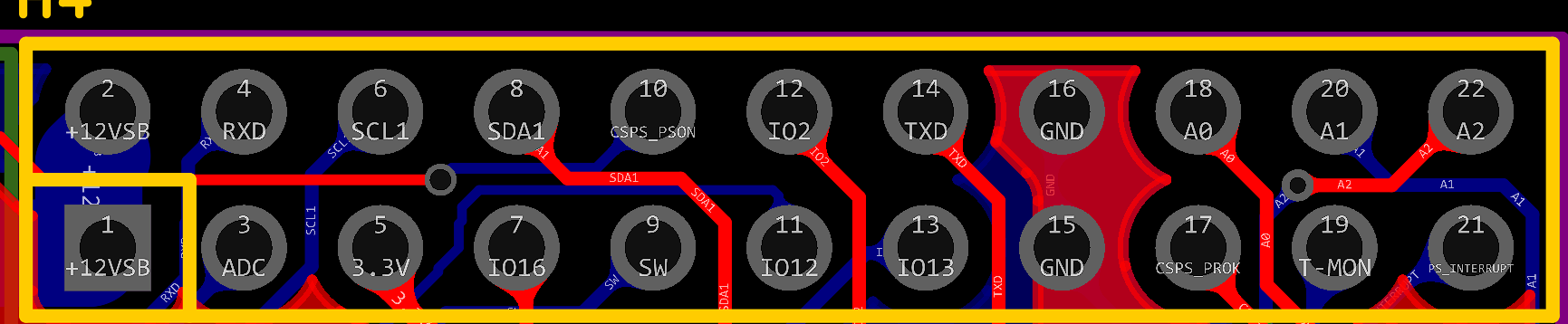
All power signal lines have been brought out. I plan to add an auxiliary control to monitor the hardware PSOK and Load Monitoring (IMON) statuses (in fact, you can also use the ADC of the 8266 directly, but I think the auxiliary control shouldn't be too idle, plus the 8266 doesn't have enough pins). I also plan to further control the power relays after the power supply (for example, separately shutting down the 12V power supply for the soldering smoking machine, the 12V power supply for the soldering pen, and the 12V input for the lithium battery charging system among a group of devices). (Sir, you don't want to forget to turn off the power when you leave and have to come back, do you? (Huang Dou's humorous comment)). Alternatively, you can skip soldering the 8266 and directly use a separate board for control. All necessary lines have been brought out.
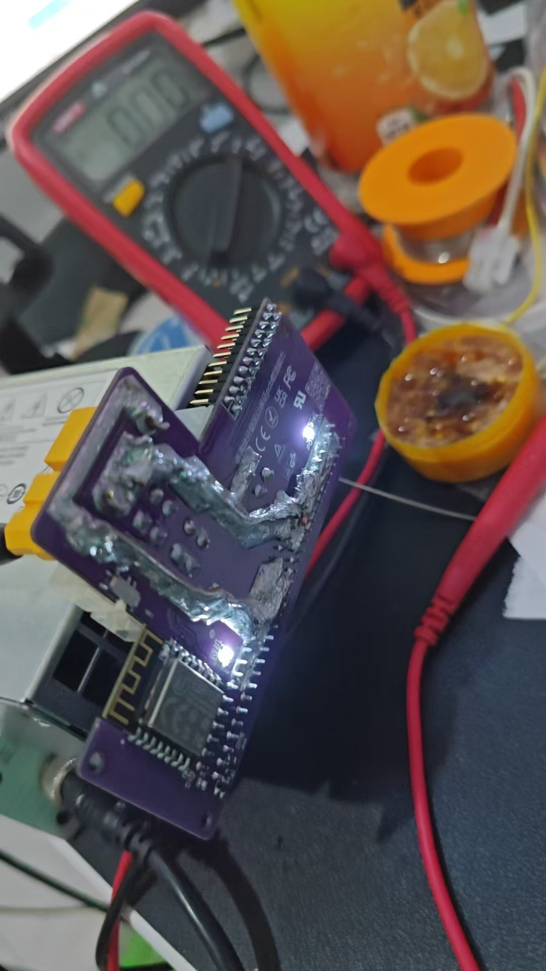
Current status:
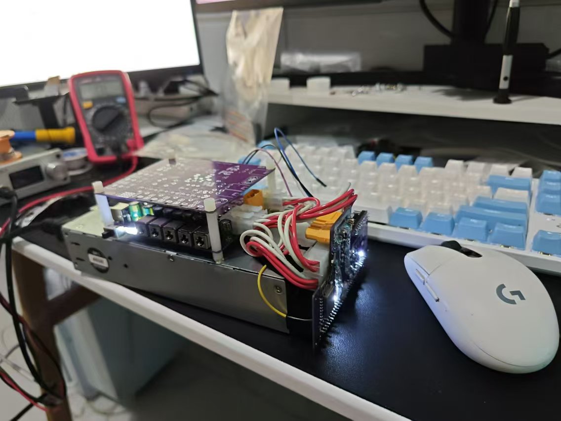
The yellow wire is used to pull GPIO0 low. Normally it's a 3.3V pull-up, but for flashing the program, this pin requires a pull-down, so a jumper wire was added. It's strongly recommended to flash the program before soldering it onto the board. This power board has too little space. There's not enough room for many components, so there will be a power distribution board later to support powering more devices. We also plan to build a fast-charging board and stack it up to create a desktop power station.

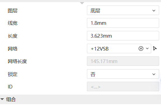
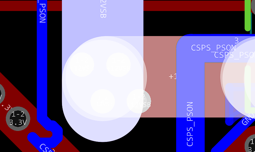
Hardware-wise, we've implemented windowing, and all lines have been calculated to ensure current carrying capacity and prevent board burnout. The 12VSB has a maximum output of 2.5A, and the design uses a minimum 1.8mm trace width. The traces have four vias with an inner diameter of 0.4mm and an outer diameter of 0.6mm for current carrying. This is more than sufficient.
According to the IPC-2221 standard, a 1.8mm wide, 1oz thick copper trace can carry approximately 6.5A of current at a 10°C temperature rise.
Line width: 1.8 mm;
Copper thickness: 1 oz (35 µm);
Current carrying capacity: Approximately 6.5 A (10°C temperature rise).
According to IPC-2221 (a common standard for printed circuit boards), a via with an inner diameter of 0.4 mm and a copper thickness of 1 oz has a current carrying capacity of approximately 1A to 2A, but this will vary depending on the PCB design, copper distribution, and heat dissipation.
Current carrying capacity: Approximately 1A to 2A.
Note: In practical applications, to ensure reliability and avoid overheating, it is recommended that the actual operating current be as low as possible below the estimated maximum current carrying capacity.
If your application requires more accurate current carrying capacity calculations, it is recommended to perform further analysis using thermal simulation software.
Please fully solder the window area to ensure current carrying capacity. The 12V and GND windows on the circuit board are at least 4mm narrow. Without solder, a single circuit board can only handle a maximum of 13A according to the IPC-2221 standard. However, the Huawei 460W design has a 38A output on 12V, so please be sure to add solder or solder copper strips. My
soldering station power was insufficient, resulting in poor soldering (crying). My

software code
is not yet finished (I'm a complete novice)
, but you can use Wuyu's code to implement remote switching. The hardware is compatible.
Here's the link: https://oshwhub.com/wuyu233/wuyu-huawei-460w-csps-esp8266-zhi-neng-qu-dian-ban
Note:
Remember to add solder to the window area during soldering. Theoretically, as long as you add enough, it can easily handle 70-80A. A single XT60 can handle 60A, two can handle 120A, which is more than enough. According to Molex specifications,
the current carrying capacity of a 4-pin 5557 connector is as follows
for the 5557 series connectors:
Rated current per pin: typically 9A (when using 18AWG wire).
The total current carrying capacity of the 4-pin connector: ideally, it can reach 36A (9A per pin). However, this depends on the heat dissipation and current distribution in the actual application.
(Mainly because XT60 is too expensive, and 5557s are only a few cents each; if the current is not high, you can consider directly wiring with 5557s).
Further update:
The attached file contains the 12V distribution board shown in the above photo. Feel free to click on it if you like; it's too simple to dedicate a separate page to. It uses a 007B12V Songle T90 relay with optocoupler-isolated I/O control and manual control.

Project contributions:
Everyone is welcome to participate and contribute to this project, improving the hardware or software code. I am a student, and the design has many shortcomings. Please feel free to point out any flaws in my work; I will optimize and improve it promptly.


 京公网安备 11010802033920号

 HG4518/060-H1GC


