I. Project Introduction
This project is a LCSC training camp project, using a CW32 development board + expansion board to build a voltage and current meter. The components are designed with basic sampling plug-in type for easy soldering.
The main control core board uses the domestic Wuhan Xinyuan Semiconductor CW32 as the main controller, while also being compatible with other similar development boards; however, the CW32 has advantages.
The training camp provides rich design documents, explaining everything from component selection to circuit design and software design, for in-depth learning.
Training camp document link: CW32 Digital Voltage and Current Meter Training Camp Project Tutorial Document | LCSC Development Board Technical Document Center (lckfb.com)
Accompanying video link: LCSC Development Board Personal Space - LCSC Development Board Personal Homepage - Bilibili Video (bilibili.com)
II. Hardware Design
1. Power Supply Circuit

LDO (Low Dropout Linear Regulator) Selection This project uses an LDO as the power supply. Considering that most actual voltage meter products are used in industrial scenarios with 24V or 36V power supplies, this project selected the SE8550K2 with a maximum input voltage of up to 40V as the power supply. The main reason for not using a DC-DC step-down circuit to handle large voltage differences in this project is to avoid introducing DC-DC ripple interference during the design process. A secondary reason is to reduce project costs.
2. Advantages of the CW32 development board
: Wide operating temperature range: -40~105℃;
Wide operating voltage: 1.65V~5.5V (STM32 only supports 3.3V systems)
; Strong anti-interference: HBM ESD 8KV; All ESD reliability reaches the highest international standard level (STM32 ESD 2KV)
; Project focus - Better ADC: 12-bit high-speed ADC, achieving ±1.0LSB INL 11.3ENOB; Multiple Vref reference voltages... (STM32 only supports VDD=Vref);
Stable and reliable eFLASH technology.
CW32's ADC main characteristics.

3. Voltage sampling circuit: The voltage
divider resistor in this project is designed to be 220K+10K, so the voltage division ratio is 22:1 (ADC_IN11).
The voltage divider resistor
is selected to measure the maximum voltage. For safety reasons, this project uses 30V (the actual maximum can be displayed as 99.9V or 100V).
The ADC reference voltage is 1.5V in this project, and this reference voltage can be configured through the program.
To reduce the power consumption of the sampling circuit, the low-side resistor (R7) is usually chosen as 10K based on experience.
Then, the high-side resistance of the voltage divider resistor can be calculated using the above parameters.
The required voltage division ratio is calculated, i.e., the ADC reference voltage. The design input voltage can be calculated using known parameters: 1.5V/30V = 0.05.
The high-side resistance is calculated as: low-side resistance/voltage division ratio. Using known parameters, 10K/0.05 = 200K.
A standard resistor is selected: a resistor slightly higher than the calculated value is chosen. The calculated value is 200K. We usually choose E24 series resistors; therefore, in this project, 220K, which is greater than 200K and closest to the calculated value, is selected.
4. Current Sampling Circuit:
This project uses a low-side current sampling circuit for current detection. The low-side of the sampling circuit shares a common ground with the development board's meter interface.
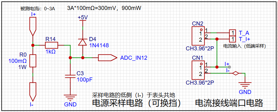
The design analysis shows
that the sampling current in this project is 3A, and the selected sampling resistor (R0) is 100mΩ. According to the formula, 3A * 100mΩ = 300mV, 900mW. The
program
defines 5 working modes. The SW1 key is used to switch the display mode. The SW2 key sets the parameter value for the corresponding mode and saves it to FLASH. The SW3 key returns to mode 0.
Mode 0: Displays normal voltage and current values (the upper row of digital tubes displays the voltage value *.V or .*V automatically, the lower row displays the current value _.**A).
Mode 1: 5V voltage calibration setting. The upper row of digital tubes displays 5.05. The lower row displays the current voltage value _.V or ._V. In this mode, the multimeter should be set to 5.00V to measure the measured bit. After pressing the SW2 key, the current value is calibrated to 5V.
Mode 2: 15V voltage calibration setting. The upper row of digital tubes displays 5.15. The next row displays the current voltage value as _.V or ._V. In this mode, the multimeter should be set to 15.0V when measuring the measured part. After pressing the SW2 key, the current value is calibrated to 15V.
Mode 3: Current 0.5A calibration setting. The upper row of the digital tube displays A.0.5. The next row displays the current current value as _.**A. After pressing the SW2 key, the current value is calibrated to 0.5A.
Mode 4: Current 1.5A calibration setting. The upper row of the digital tube displays A.1.5. The next row displays the current current value as *.**A. After pressing the SW2 key, the current value is calibrated to 1.5A.


 京公网安备 11010802033920号

 ILC5061AIC34


