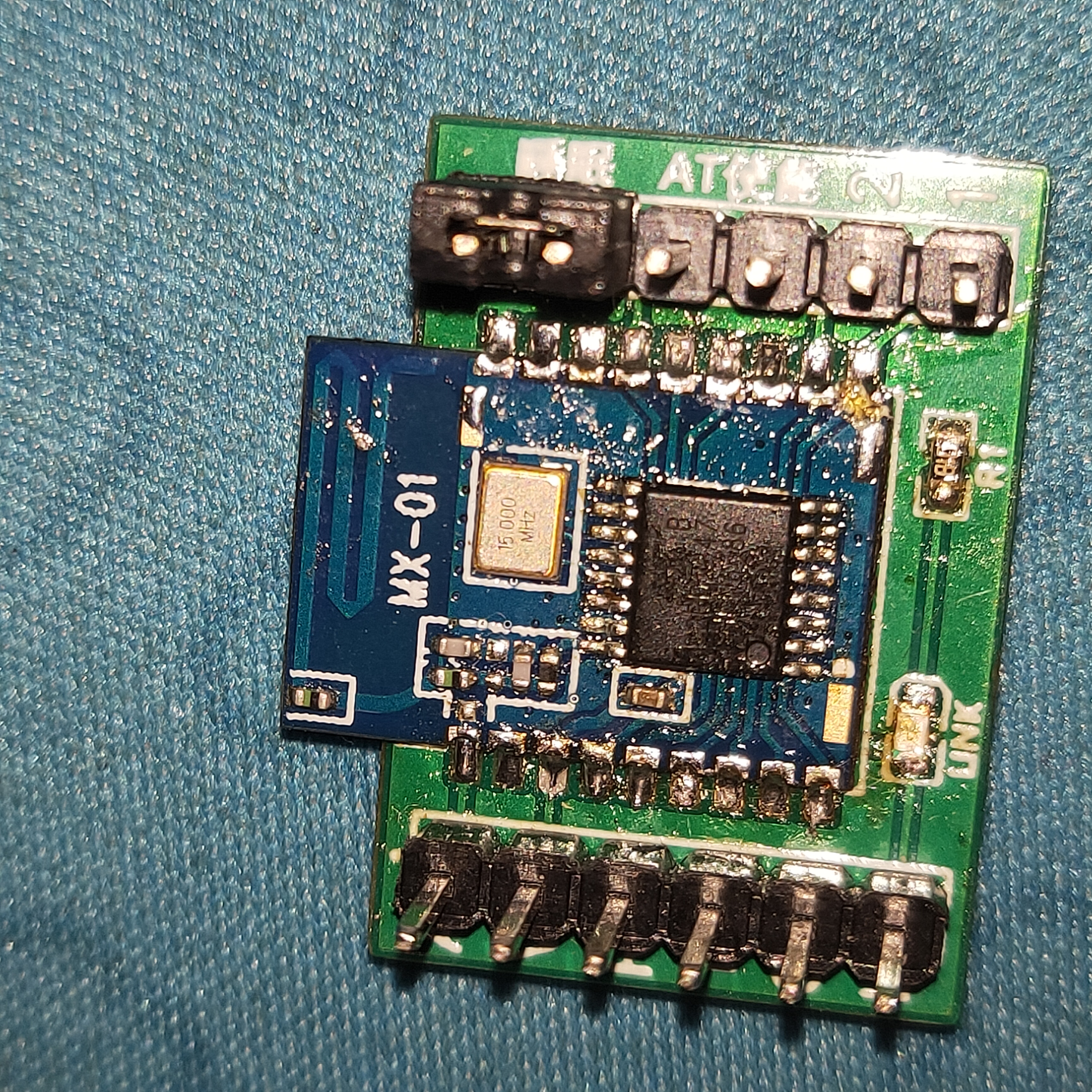
It has been verified that the IO1 and IO2 labels in
the MX-01 Bluetooth module baseboard
are reversed. The network configuration has not been changed, but the labels on the PCB have been corrected.
MX-01 Demo Document.pdf
MX-01._package.rar
01A_Dimension Drawing A.pdf
iOS test app.jpg
Android test app.jpg
Mini Program.rar
PDF_MX-01 Bluetooth Module Baseboard.zip
Altium_MX-01 Bluetooth Module Baseboard.zip
PADS_MX-01 Bluetooth Module Baseboard.zip
BOM_MX-01 Bluetooth Module Baseboard.xlsx
92830
DC-DC verification MP1584 SY8205
Output ripple study of MP1584, MP2451, SY8205, and SY8201, with calculation formula for FB voltage divider resistor.
**Disclaimer: I am an amateur in power supply design; this article is for reference only.**
This is an MP1584 and MP2451 power supply I designed several years ago. At that time, I had no concept of ripple. Recently, during testing, I found that under heavy load (above 2A), the ripple reached over 300mV, and in some circuits, it reached 600mV.
To reduce the ripple, I tried adding multiple large-capacity electrolytic capacitors to the input and output of the old board, but found that it did nothing to reduce the ripple.
After some research, I realized that low-ESR capacitors should be used for the input and output. My board has a 100uF electrolytic capacitor + 100nF ceramic capacitor at the input and a 22uF ceramic capacitor + 100nF ceramic capacitor at the output.
I discovered that the company's designed boards almost always used a combination of (22uF + 10uF + 100nF + 10nF ceramic capacitor) + (220uF/470uF electrolytic capacitor) or (10uF + 4.7uF + 100nF + 10nF ceramic capacitor) + (220uF/470uF electrolytic capacitor) for input and output.
After removing all the electrolytic capacitors from the old boards and replacing them with a single 10uF ceramic capacitor at the input, the ripple significantly decreased. Subsequently, changing the inductor value to a larger one further reduced the ripple; some ripple levels were reduced to 170+mV, while others remained above 300+mV.
This demonstrates that power supply capacitors must first meet low ESR requirements, and then capacitance should be considered. If the ESR is not low enough, adding large capacitors is futile. Theoretically, combining multiple capacitors can achieve an even lower ESR.
The issues with the ripple that couldn't be reduced were likely due to wiring problems, such as insufficient ground vias, excessively long ground loops, or the top and bottom layer GND wires near the DC-DC chip taking a long detour before connecting.
For example, one of our clients had a board designed and sent to Gerber for manufacturing. We discovered that the ripple was very high and the power supply quality was poor, resulting in a high product defect rate. Thousands of boards had to be reworked. The direct cause was that the client's board design had almost no GND vias, and the GND traces were thin and took a long detour before connecting. It was the kind of design where all the wires were connected and there were no error messages, so they considered it OK.
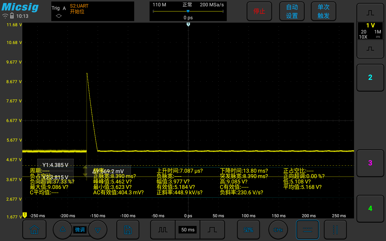
The above measurements were taken without an electrolytic capacitor. Low-ESR ceramic capacitors are used to smooth high-frequency ripple, while electrolytic capacitors are used to smooth low-frequency ripple. Without an electrolytic capacitor, the following will occur: a very high or very low voltage spike will appear when the load suddenly increases or decreases, as shown in the image below.

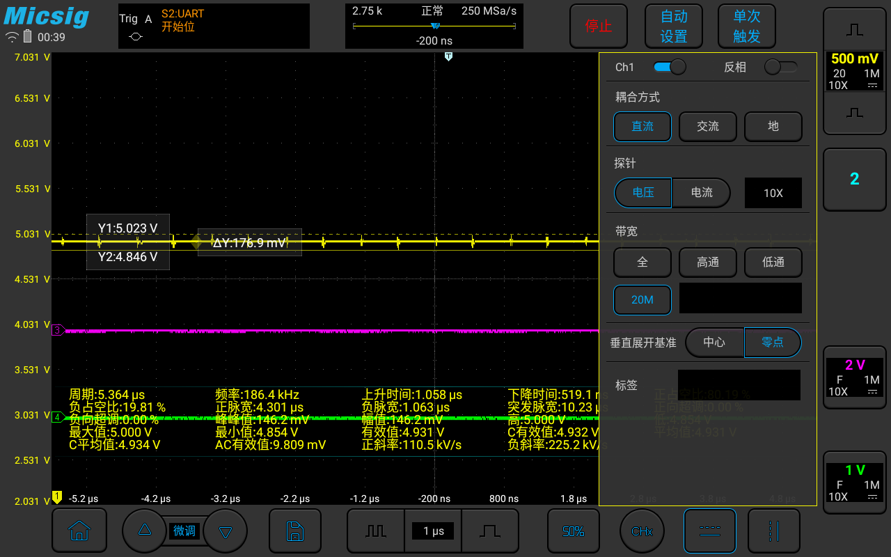
Adding a 470uF or larger electrolytic capacitor will effectively suppress this. If the 10uF + 100nF ceramic capacitor combination at the input still has significant ripple, add a 4.7uF and a 10nF capacitor as shown in the image above; the ripple will be perfectly suppressed. ![IMG_20240822_224221.jpg] The newly designed board uses a 4-layer design with as many ground vias as possible to ensure ground integrity (I'm not sure if this term is appropriate for me, haha). The ripple is lower and the temperature is significantly reduced. The advantage of lower temperature is that it can continuously output high current. The old board stopped outputting above 2.5A, but this version can continuously output above 3.5A, which is largely thanks to the 4-layer design. However, exceeding the rated current results in a very high temperature, and the ripple reaches over 250 Hz. Adding a solid-state capacitor in parallel didn't reduce the ripple further, so it was omitted. Ceramic capacitors produce a buzzing sound; I'll try replacing the uF ceramic capacitors with solid-state capacitors in the future. (The input electrolytic capacitor is not soldered; the output solid capacitor needs to be replaced with a large-capacity electrolytic capacitor. This will be added upon arrival.) ![IMG_20240821_001520.jpg] ![IMG_20240819_004250.jpg] Ripple at the USB port is 170+, and at the output capacitor it is tens of mV . ![Screenshot_20240819-003953.png] The MP1584 seems to be discontinued; you can replace it with the SY8205, which supports higher current, lower temperature, requires less inductance, and has lower ripple . ![IMG_20240821_001808.jpg] ![Screenshot_20240819-232849.png] **Calculation of the voltage divider resistor values for the FB pin under different output voltages; download the attachment and study it yourself.**


MP1584 MP2451 SY8205 SY8201 FB voltage divider resistor calculation.xlsx
PDF_DC-DC Verification MP1584 SY8205.zip
Altium_DC-DC verification MP1584 SY8205.zip
PADS_DC-DC Verification MP1584 SY8205.zip
BOM_DC-DC Verification MP1584 SY8205.xlsx
92831
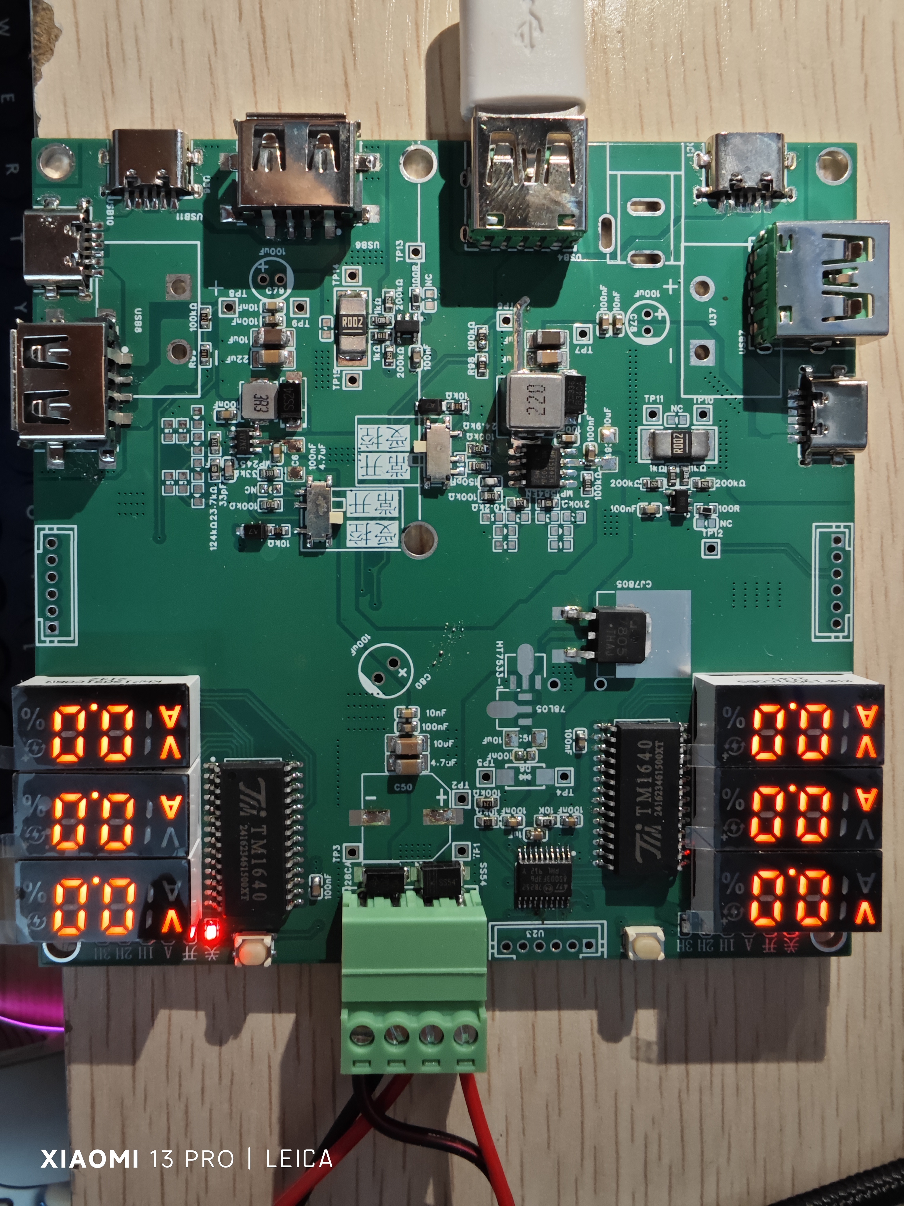
Based on CW32F030C8T6 voltage and current meter
Based on CW32F030C8T6 voltage and current meter
This training camp, which focuses on building a voltmeter and ammeter based on the CW32F030C8T6, didn't teach beginners step-by-step PCB design. However, Mr. Li's solid foundation and dedicated instruction significantly improved learners' skills.
This project features several key characteristics:
it employs a core board plus expansion board design concept, utilizing plug-in components for simplified learning and deeper exploration;
the core board uses the domestically produced Wuhan Xinyuan Semiconductor CW32 as the main controller, while also being compatible with other similar development boards, though the CW32 offers advantages;
the project is highly comprehensive and practical, and the completed design can be used as a desktop instrument;
the project provides abundant learning materials, including circuit design tutorials, PCB design, code programming, and training for engineers' debugging skills.
PDF_Based on CW32F030C8T6 Voltmeter and Ammeter.zip
Altium-based CW32F030C8T6 voltmeter and ammeter (zip file)
PADS_Based on CW32F030C8T6 Voltmeter and Ammeter.zip
BOM (Building Document) based on CW32F030C8T6 voltage and current meter.xlsx
92832
electronic


 京公网安备 11010802033920号

 IDT72V241L10PF


