This project is developed using the LCSC CW32F030C8T6 development board. More information can be found at the following link:
https://wiki.lckfb.com/zh-hans/dwx-cw32f030c8t6/
1. Power
Supply Procurement:
This device can be powered in two ways:
DC power supply
and Type-C interface components on the development board. Most components can
be ordered
directly from the LCSC online store using the BOM (Bill of Materials). If the price is too high, you can also purchase them yourself based on the BOM. Note that
the following components may not be included in the BOM: 20P
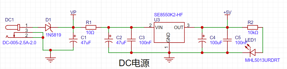
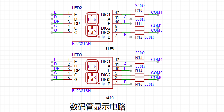
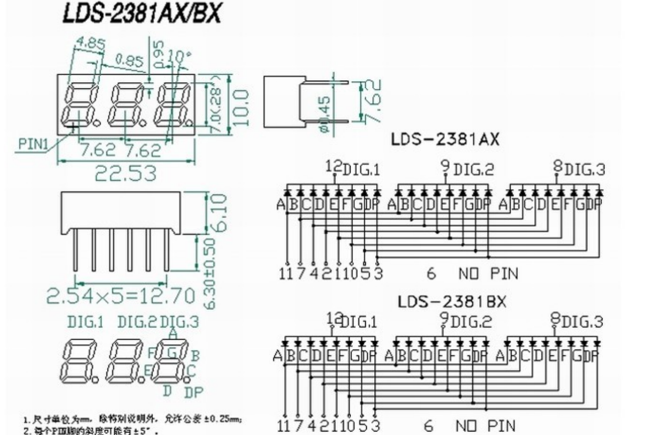
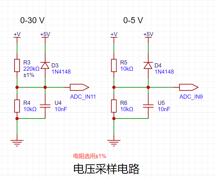
jumper caps , 2M copper pin headers (models: M23+3 and M28+3), and M2 screws (recommended length 4-5MM) . These components can be purchased from the LCSC online store or Taobao. Panel Design: Panels can be ordered directly from JLCSC. Acrylic material is recommended, with a thickness not exceeding 2MM. Two panel designs are provided for selection. 3D Shell: 3D shells can be ordered directly. After prototyping, I felt the top cover wasn't aesthetically pleasing and obscured the color silkscreen printing. Therefore, I only used the base of the outer shell. The base is connected using M23+3 copper posts, and then the acrylic panel is connected using M28+3 copper posts and screws. The button design utilizes the relatively long buttons chosen, allowing the panel's elasticity to be easily pressed. For a better feel, longer buttons could be chosen, or the height of the top copper posts or the thickness of the acrylic panel could be appropriately reduced. 2. For detailed hardware design information, please refer to the training camp document: Hardware Design MCU Selection . This project uses the LCSC Diwenxing development board as the main controller, directly connected to the PCB via a 20-pin header, which greatly reduces the difficulty of development and soldering. Advantages of CW32 : Wide operating temperature range: -40~105℃; Wide operating voltage range: 1.65V~5.5V (STM32 only supports 3.3V systems); Strong anti-interference: HBM ESD 8KV; All ESD reliability reaches the highest international standard level (STM32 ESD 2KV); Project focus - Better ADC: 12-bit high-speed ADC, achieving ±1.0LSB INL 11.3ENOB; Multiple Vref reference voltages (STM32 only supports VDD=Vref); Stable and reliable eFLASH technology. Power supply circuit: The DC power supply LDO is selected as SE8550K2-HF, with a maximum allowable input voltage of 40V, output voltage of 5V, and output current of 250mA. Considering that high voltage reverse connection will cause irreversible damage to the module, the voltmeter power supply circuit adopts a series diode scheme for reverse connection protection. The digital tube circuit uses 0.28-inch 3-digit common cathode digital tubes. The BOM lists two red digital tubes; if other colors are needed, digital tubes of the same specifications from the same manufacturer can be selected. Note: If choosing a different manufacturer, please consult the datasheet to check if the pinout and other parameters are compatible. Compared to a display screen, digital tubes offer better visibility in complex environments and have better mechanical properties, making them less susceptible to damage from external forces. A 300Ω current-limiting resistor is used for the digital tubes, ensuring good visibility and a soft, non-glaring brightness. The voltage sampling circuit uses a voltage divider resistor of 220K+10K with a voltage division ratio of 22:1 (for the ADC channel ADC_IN11). This project includes an additional voltage sampling circuit; therefore, we can discuss the significance of range switching for improving measurement accuracy. Multimeters often have multiple range settings for more accurate measurements. By adjusting different ranges, the optimal measurement accuracy of the measured point within the corresponding range can be obtained. Implementing this function in this project requires a combination of hardware and software. When we first use the ADC_IN11 channel mentioned earlier to measure voltages up to 30V, if the measured voltage is within 0~3V, then we use the ADC_IN9 channel for measurement. At this point, due to the reduced voltage division ratio, the measurement accuracy is greatly improved. There are many ways to implement range switching, and the development board design provides more design possibilities. The voltage sampling circuit board carries analog voltage measurement, measurement calibration, and measurement calibration auxiliary circuitry. There is no need to build external circuits for testing and debugging; simply short-circuit JP1 with a jumper cap (long-handled jumper caps are recommended), and then adjust the multi-turn adjustable potentiometer to simulate the voltage. It also has two 2mm banana-head female connectors, T_V and TGND, for easy insertion of multimeter probes for measurement and calibration. The sampling current circuit in this project is designed for a sampling current of 3A. The selected sampling resistor (R0) is 100mΩ. The selection of the sampling resistor mainly needs to consider the following aspects: the maximum value of the pre-designed measurement current; the voltage difference caused by the 3A current sensing resistor in this project; and the power dissipation of the current sensing resistor, which should generally not exceed 0.5V. A suitable package should be selected based on this parameter. Considering the power dissipation (temperature) issue under high current, a 1W packaged metal wire-wound resistor was selected . The voltage amplification factor across the current sensing resistor: No operational amplifier is used in this project to build an amplification circuit, so the factor is 1. The current sensing resistor value can then be calculated using the above parameters . Since no amplifier circuit is used, a larger sampling resistor is needed to obtain a higher measured voltage for measurement. Considering that a larger resistor would result in a larger voltage drop and higher power consumption, an unlimited selection of a larger resistor is not feasible. This project uses a 1W package resistor, corresponding to a power rise of 1W. Based on the above data, a 100mΩ current sensing resistor was chosen. According to the formula, 3A * 100mΩ = 300mV, 900mW. To handle different operating environments, especially high-current scenarios, the R0 resistor can be replaced with constantan wire or a shunt. The choice of alternative can be based on the specific application scenario. For safety and educational purposes, this project will not discuss measurements exceeding 3A, but the principle remains the same. The current sampling circuit has two current sampling interfaces, CN1 and CN2, for convenient debugging. For normal measurements, only CN2 needs to be connected. When a multimeter or similar device needs to be connected in series for comparison and verification in a project, pin 1 (red wire - current in) and pin 2 (black wire - current OUT) of CN1 should be used simultaneously to simulate current measurement , calibration, and auxiliary circuitry. Similar to voltage measurement, this circuitry is set up for easy learning. When using this circuit, do not solder the sampling resistor R0. When not in use, simply disconnect the jumper cap of H3.

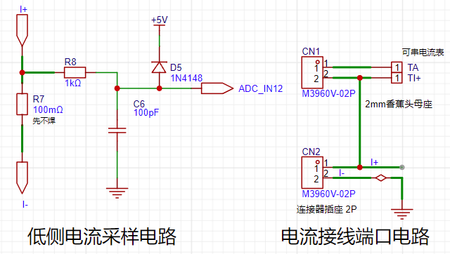
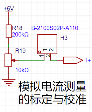
The essence of current sampling is to collect the voltage drop across the sampling resistor when current flows through it, i.e., to collect the voltage value. This circuit uses RP2 to provide a voltage value in the range of 0 ~ 0.238V (5V ÷ 210K * 10K), which is connected to the chip's current sampling pin via the I+ network.
In actual use, the voltage at I+ simulates the voltage drop across the unsoldered 100mΩ sampling resistor. Therefore, the simulated measured current value I
measured = this voltage value Vi+ ÷ 100mΩ, which is also exactly equal to the measured voltage value multiplied by 10. That is, it provides a simulated current measurement of 0~2.38A.
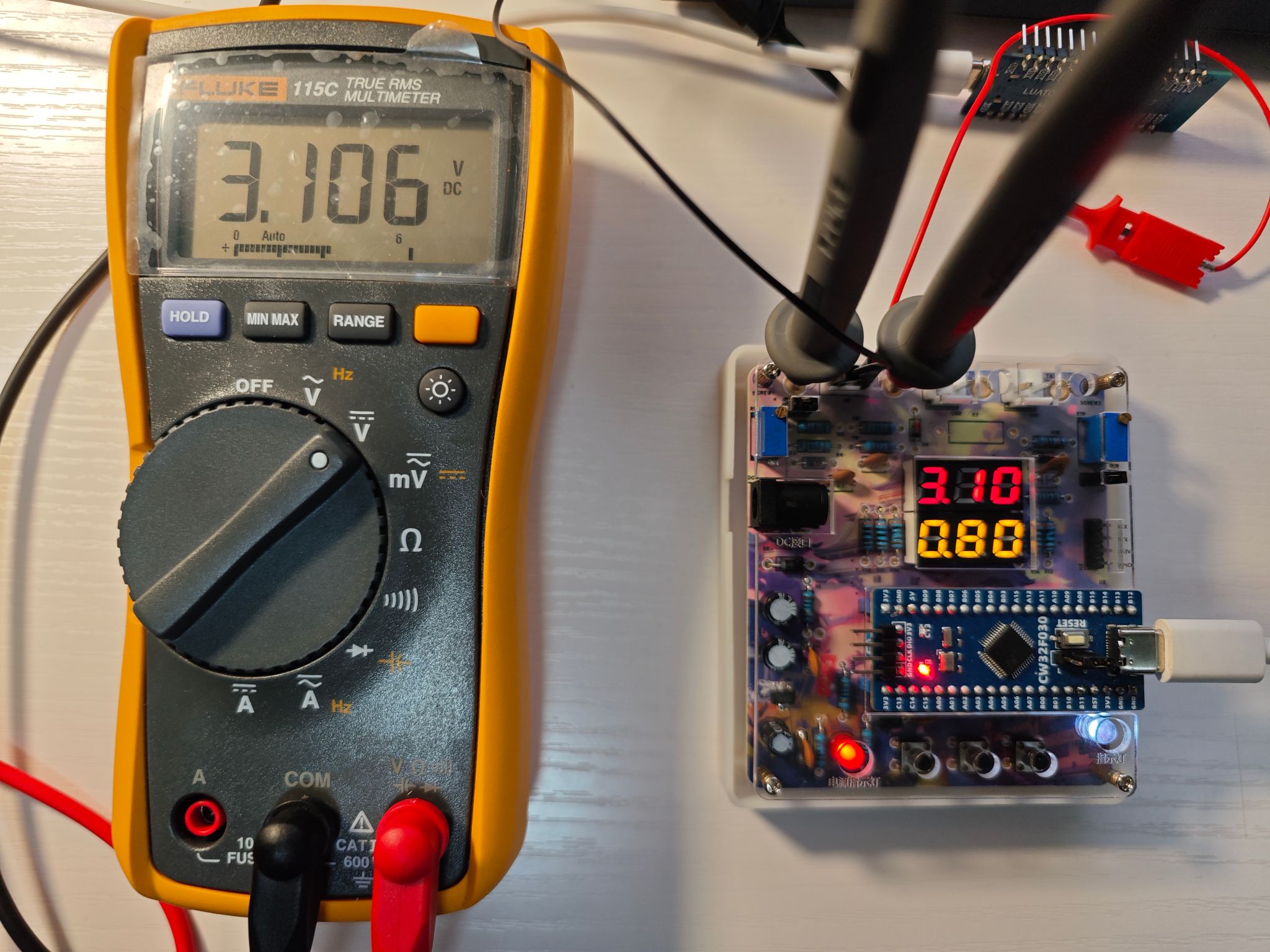
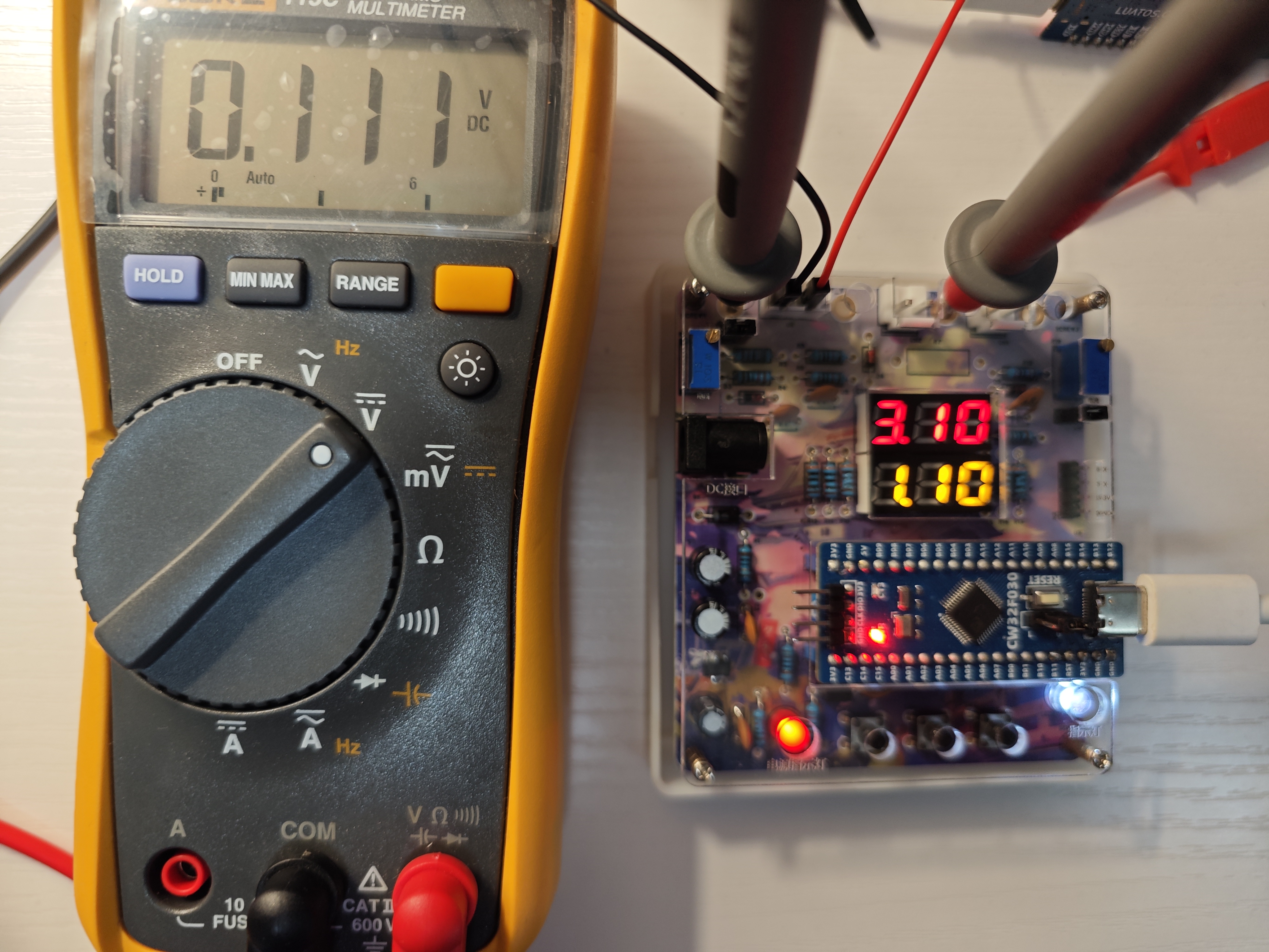
Set a multimeter or high-precision benchtop digital multimeter to the voltage measurement port, with a range within 3V. Insert the black negative probe into the T_GND interface next to the voltage measurement terminal, and the red positive probe into the TI+ port for current measurement to measure the actual voltage value of I+. Therefore, this circuit can not only complete the above design tasks, but also allow for a direct test to experience the accuracy of the MCU's ADC peripheral. You can write your own program to verify this.
3. Software Part
: The board has three buttons, K1, K2, and K3. For detailed instructions
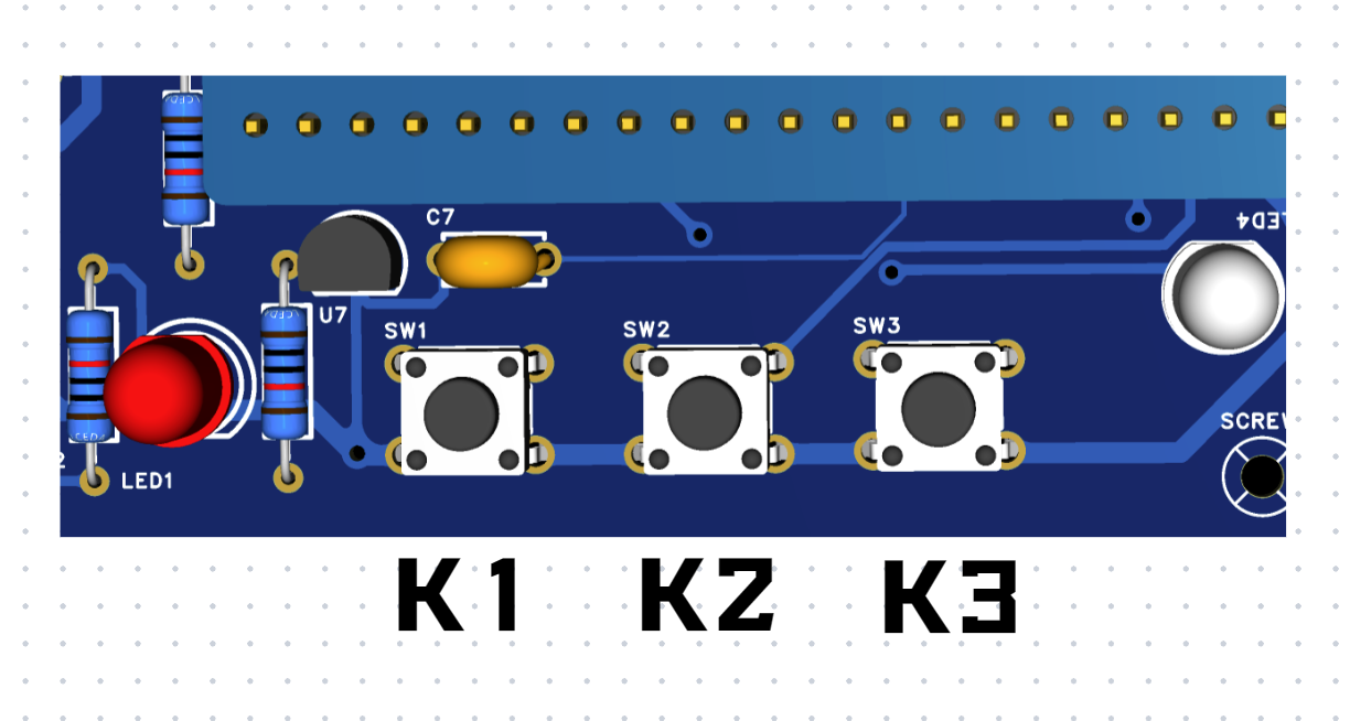
on serial

port firmware programming, please refer to the attached file. The compiled firmware (ending in hex) is provided; you can directly use CW Programmer V1.53 to flash the program onto the development board. Note: When programming via serial port, you need to switch the jumper cap on the development board to 1; after programming, you need to switch it back to 0. 4. Conclusion: As a beginner participating in LCSC's training camp for the first time, this camp helped me understand some basic principles of voltmeters and ammeters. I also used LCSC's 3D printing for panel customization for the first time, and the results were quite good!


 京公网安备 11010802033920号

 HLMP-4740D0BA1


