I. Project Function Introduction
The project's functions include:
Voltage Measurement: Accurately measures DC voltage and displays real-time voltage values.
Current Measurement: Accurately measures DC current and displays the current current value.
Calibration Function: Provides calibration interfaces and methods to ensure the accuracy of measurement results.
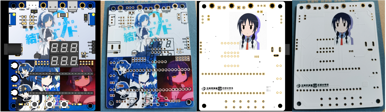
Physical Demonstration:

II. Hardware Design
1. MCU Selection: This project uses the LCSC CW32F030C8T6.
Key advantages of the CW32 in this project:
• Wide operating temperature range: -40~105℃
• Wide operating voltage range: 1.65V~5.5V (STM32 only supports 3.3V systems)
• Strong anti-interference: HBM ESD 8KV, all ESD reliability reaches the highest international standard level (STM32 ESD2K)
• Project focus - Better ADC: 12-bit high-speed ADC, achieving ±1.0LSB INL 11.3ENOB, multiple Vref reference voltages... (STM32 only supports VDD=Vref)
• Stable and reliable eFLASH technology.
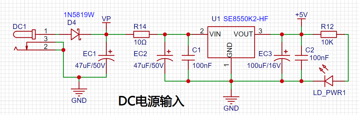
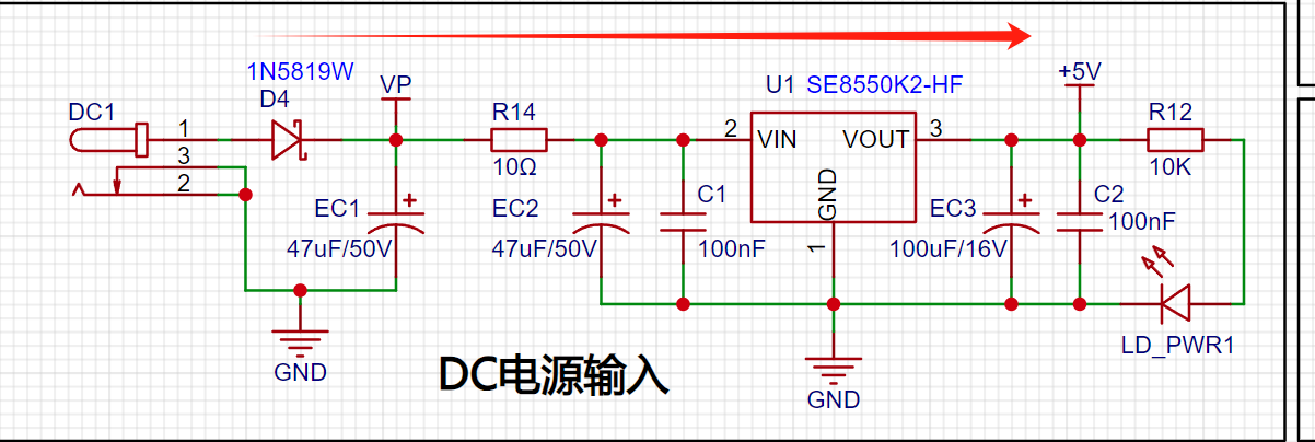
2. Power Supply Circuit: The LDO selected is the SE8550K2, which can input a maximum voltage of 40V. However, for safety reasons, voltages exceeding 30V should be avoided. Alternatively, the Type-C interface or programming port on the development board can be used for power supply.
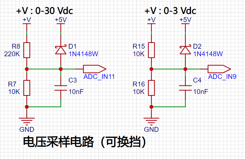
3. Voltage Sampling Circuit: Designed to sample voltages up to 100V, but for safety, the actual configuration is 0-30V. A voltage divider circuit is composed of 220KΩ and 10KΩ resistors, resulting in a voltage division ratio of 22:1. The ADC reference voltage in this project is 1.5V. A 1N4148 diode is used as a clamping diode to prevent damage to the MCU due to excessive input voltage. Diode clamping limits the voltage amplitude and protects the circuit from overvoltage damage. An additional voltage sampling circuit is added, selecting different sampling channels based on the actual voltage to improve measurement accuracy. Switching to a higher-precision channel is used within the 0-3V range for measurement.
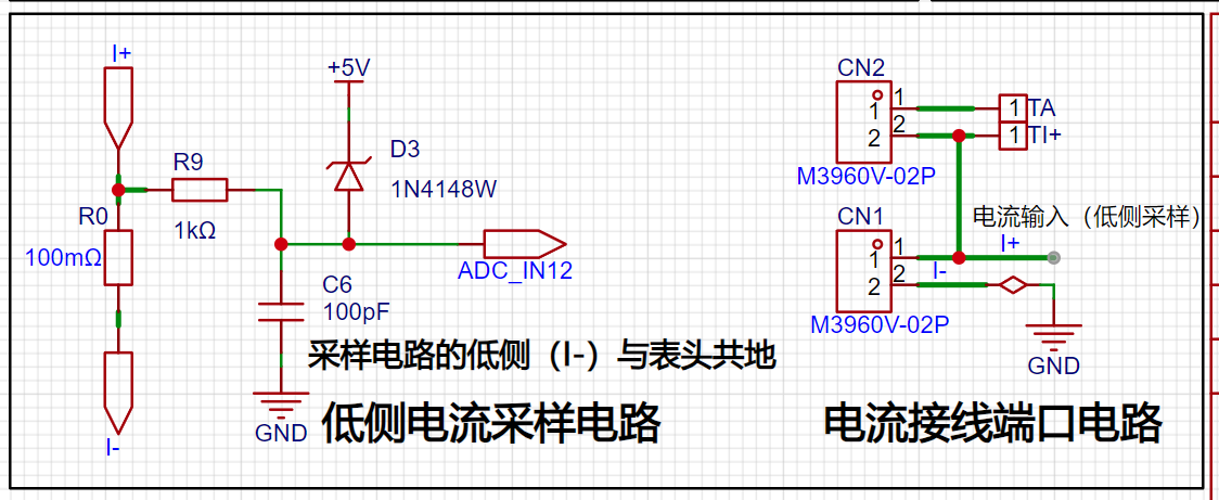
4. Current Sampling Circuit: A low-side current sampling circuit is used for current detection. The low-side of the sampling circuit shares a common ground with the development board's meter interface. 5. Select a 100mΩ sampling resistor (be sure to choose a large package, such as 2512, or use a through-hole resistor) to detect a maximum current of 3A.

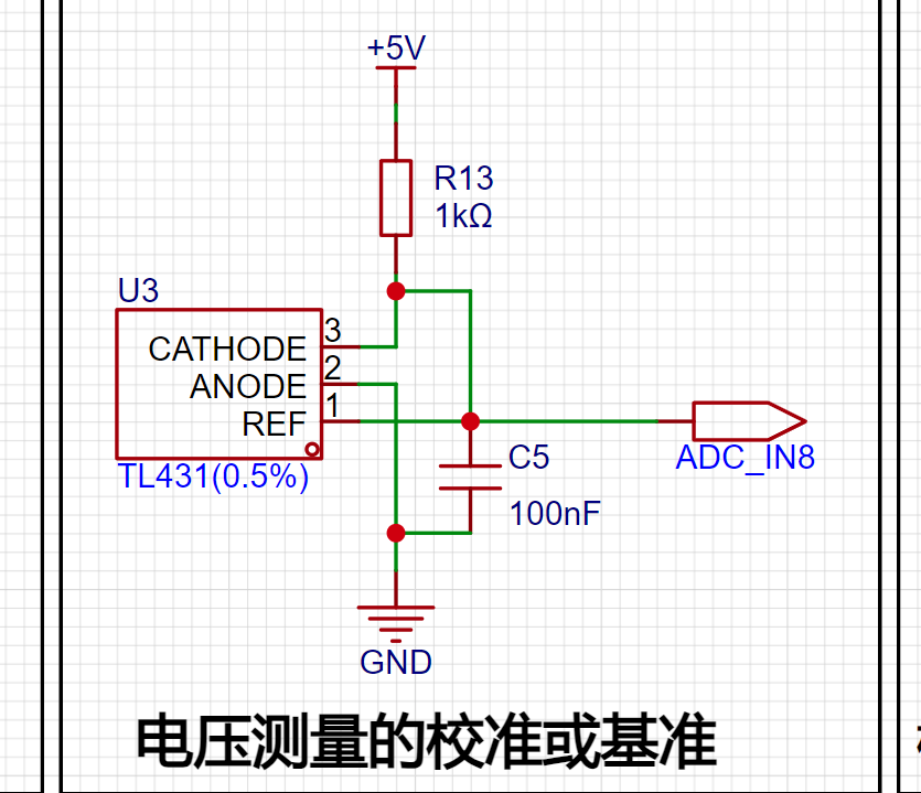
6. Voltage Measurement Calibration TL431 Circuit Design: An additional TL431 circuit is added to provide a 2.5V reference voltage, which can be used to provide an external voltage reference for the chip to calibrate the AD converter.
7. Digital Tube Display: Two 0.28-inch three-digit common-cathode digital tubes are used as display devices, with a 300Ω current-limiting resistor for the tubes.

8. LED Indicator: A power indicator and an LED connected to the microcontroller's PC13 port are added to the power supply circuit.

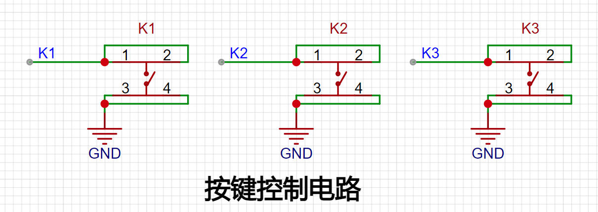
9. Button Circuit Design: Three buttons are provided for user use.
9. PCB Design:
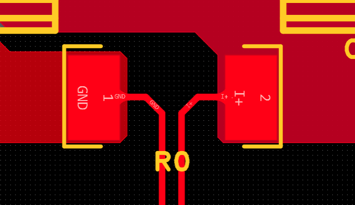
Kelvin Connection of Current Sampling Resistor:
When placing the DC power interface and the pin header connecting the development board, pay attention to the placement position and distance (the center-to-center spacing of the pin headers connecting the development board is 600mil).

The DC power input should be placed sequentially according to the schematic diagram.
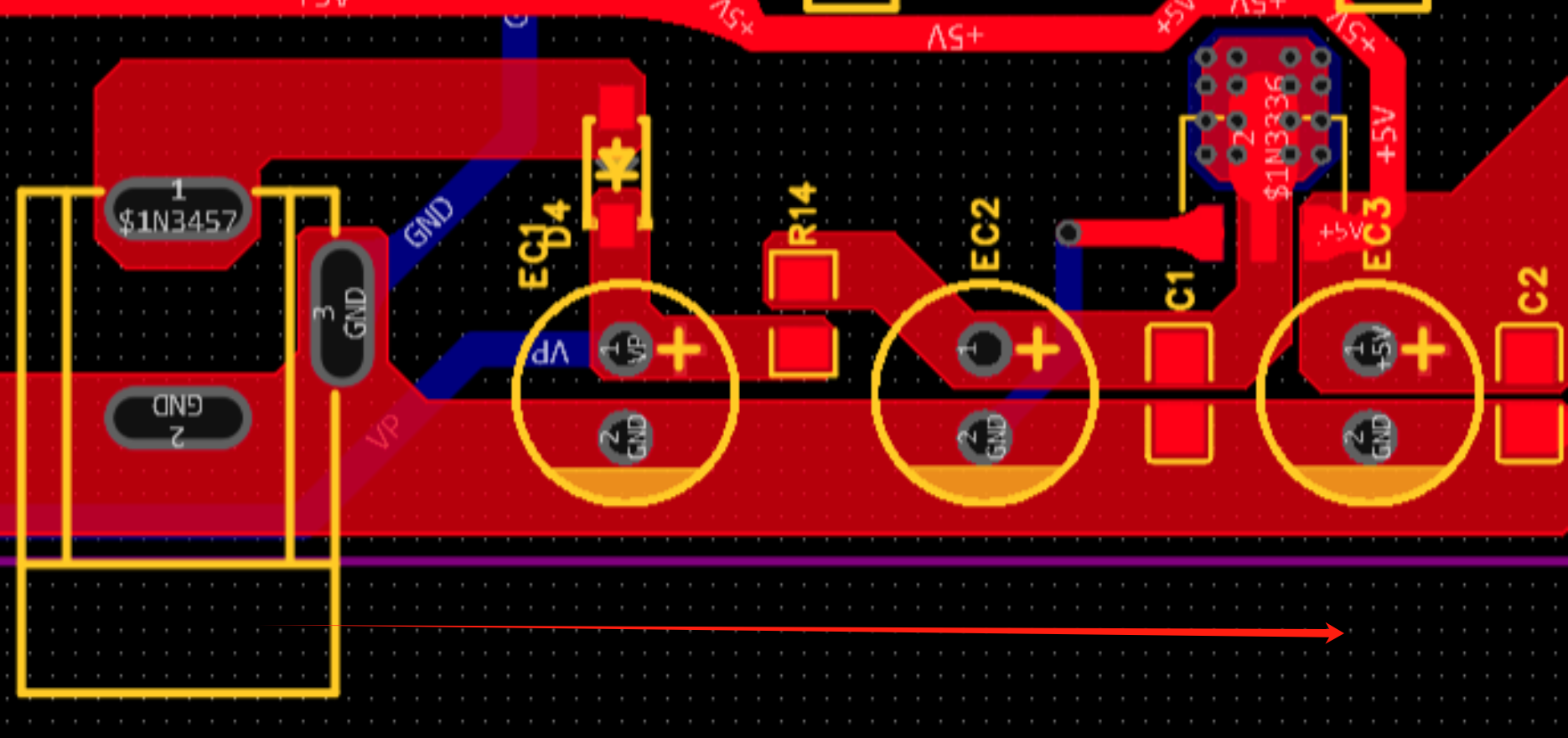
When using copper pour for the current sampling section, do not use the default divergent connection method with the pads; choose direct connection or use fill.

DRC Design Considerations:
Power traces should be as wide as possible, approximately 20-60mil.
Ordinary signal lines: around 10mil
. ADC signal traces: 10mil or 8mil. Too wide a trace may affect signal integrity when the line is too long.
III. Software Section
1. Concept of Calibration:
Calibration is the process of compensating for instrument system errors by measuring the deviation of a standard, thereby improving the accuracy and precision of the instrument or system. To improve the measurement accuracy and precision of voltage and current meters, calibration is required.
The common calibration principle is as follows:
Assume a sampling system where the AD part can obtain digital quantities, and the corresponding physical quantities are voltage (or current);
1. If an AD value point Xmin is calibrated at the "zero point" and an AD value point Xmax is calibrated at the "maximum point", according to the principle that "two points form a straight line", a straight line connecting the zero point and the maximum point can be obtained. The slope k of this line is easy to obtain. Then, by applying the equation of the straight line to solve for each point X (AD sample value), the physical quantity (voltage value) corresponding to the AD value can be obtained:

The slope k in the figure above:
k = (Ymax-Ymin)/(Xmax-Xmin)
(Because the first point is the "zero point", Ymin = 0 above)
Therefore, the physical quantity corresponding to the AD value at any point in the figure above:
y = k×(Xad-Xmin)+0
The above algorithm only calibrates between the "zero point" and the "maximum point". If the intermediate AD sample value is used, it will bring a large error in the corresponding physical quantity. The solution is to insert more calibration points.
As shown in the diagram below, four calibration points (x1, y1), (x2, y2), (x3, y3), and (x4, y4) are inserted.
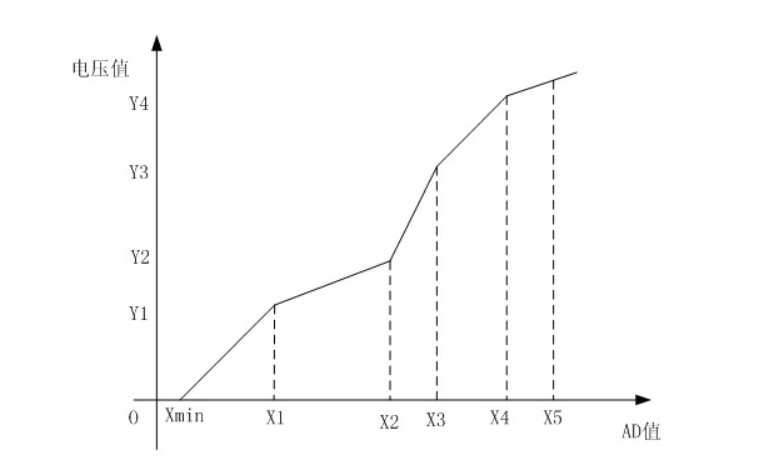
This results in a line that is no longer a straight line but a "reflected line" (equivalent to segmented processing). To calculate the voltage value corresponding to a point Xad between x1 and x2:
y = k × (Xad – X1) + y1.
It can be seen that the more calibration points inserted, the higher the accuracy of the physical value.
When measuring voltage and current, a voltage and current calibration board or multimeter can be used to calibrate the collected voltage and current. The more calibration points, the more accurate the measurement.
2. Program Section:
The source program uses three calibration points. The voltage calibration points are 0V, 5V, and 15V. The current calibration points are 0A, 0.5A, and 1.5A. However, since I currently do not have power supply equipment above 15V, the voltage calibration points have been reset to 0V, 5V, and 10V. Therefore, the following programs are all written around these three values.
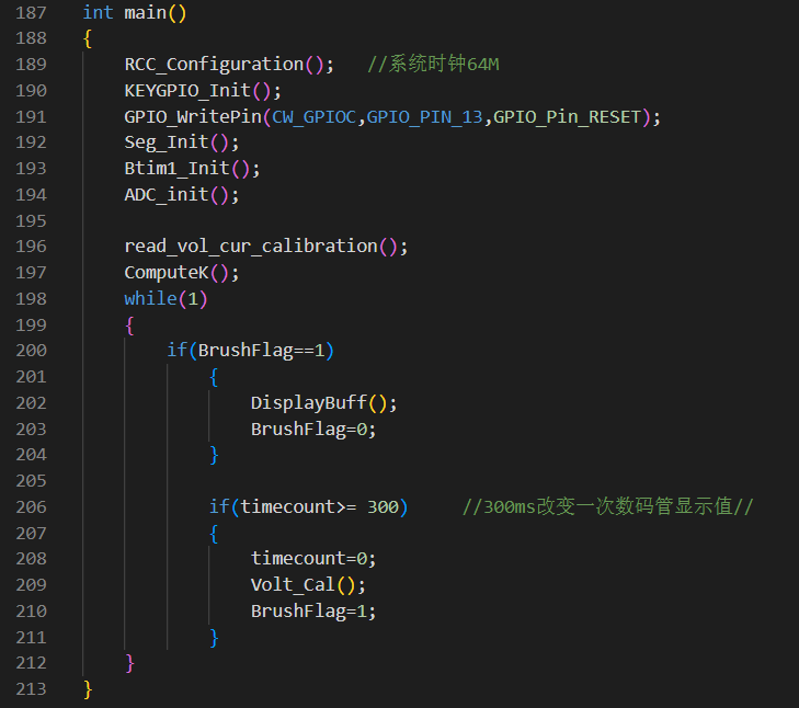
The main program code is as follows:
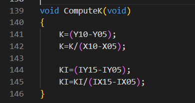
The calibration code calculation slope function is as follows:
The calibration storage function is as follows:

3. Burning Notes: When burning, you must select the correct programmer (select according to your own programmer).

IV. Calibration Settings
1. Five display modes and four calibration selections:
Mode 0: Displays normal voltage and current values (the upper row of digital tubes displays the voltage value *.V or .*V automatically switches, and the lower row displays the current value, _.**A).
Mode 1: 5V voltage calibration value setting. The upper row of digital tubes displays U.05. The lower row displays the current voltage value *.**V. In this mode, the multimeter should be used to measure the measured bit and adjusted to 5.00V. After pressing the K2 key, the current value is calibrated to the 5V voltage value.
Mode 2: 10V voltage calibration setting. The top row of the digital display shows U.10. The bottom row shows the current voltage value *.**V or **.*. In this mode, the multimeter should be set to 10.0V to measure the voltage being measured. Pressing the K2 key will calibrate the current value to 10V.
Mode 3: 0.5A current calibration setting. The top row of the digital display shows A.0.5. The bottom row shows the current current value *.**A. Pressing the K2 key will calibrate the current value to 0.5A.
Mode 4: 1.5A current calibration setting. The top row of the digital display shows A.1.5. The bottom row shows the current current value *.**A. Pressing the K2 key will calibrate the current value to 1.5A.
In modes 1-4, you can directly return to mode 0 by pressing button 3.
2. Voltage Calibration: (The calibration method for 5V and 10V is the same; two values need to be calibrated for accurate measurement.)
Use a DC power supply as the input and connect the jumper cap at JP1.
Connect the black probe of the multimeter to TGDND and the red probe to T_V.
Switch the mode to mode 1 using button 1.
Adjust RP1 until the multimeter displays 5.00V, then press button 2 to calibrate.
After calibration, press button 3 to return to mode 0.

3. Current Calibration: (The calibration method for 0.5A and 1.5A is the same; two values need to be calibrated for accurate measurement.)
Current calibration uses a voltage simulation method. The voltage displayed on the multimeter = R0 (0.1Ω) * actual current. Therefore, the voltage displayed on the multimeter * 10 can be considered the actual current value. (Do not solder R0 during calibration.)
Use a DC power supply as the input and connect the jumper cap at JP2.
Connect the black probe of the multimeter to TGDND and the red probe to TI+.
Switch to mode 3 using button 1.
Adjust RP2 until the multimeter displays 0.05V, then press button 2 to calibrate.
After calibration, return to mode 0 using button 3.

V. Appearance and Housing
1. JLCPCB Color PCB Design: The PCB design utilizes JLCPCB's color silkscreen printing process for a more attractive and aesthetically pleasing appearance.
2. JLCPCB Panel Design: The panel design is based on JLCPCB's technology and customized through the LCPCB online store. The panel uses a thin-film panel, which is highly transparent, blister-free, 0.2mm thick, and provides strong light shielding. The adhesive used is 3M9448A. It can be attached to a 3D housing.
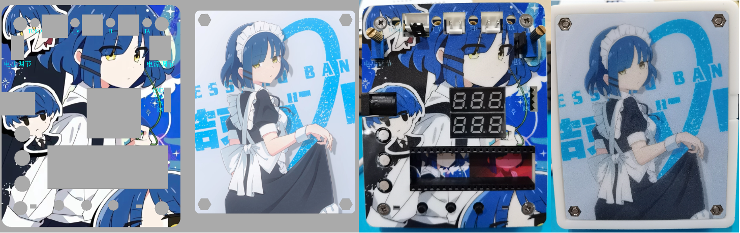
3. 3D Housing Design: The housing was designed in SolidWorks and 3D printed by JLCPCB. The housing uses a top and back cover design, assembled with M3 screws and M3 nuts. (The screw length is 16mm)

Demonstration Video: [LCPCB Development Board] CW32 Voltage and Current Meter_Bilibili_bilibili


 京公网安备 11010802033920号

 4308T-102-3121DAL


