 The 3D shell is shown below; the top cover is open and has M2 screw holes, with recessed areas for the three buttons for easy operation. Because the shell itself is not very tall, there is no space reserved for the front panel.
  One issue is the LED indicator lights. The placement of the two LED indicator lights wasn't considered much at the time of installation, and it was only after plugging in the CW32 that it was discovered that the CW32 board directly blocks these two LEDs, making them invisible from directly above, which is a bit awkward.
 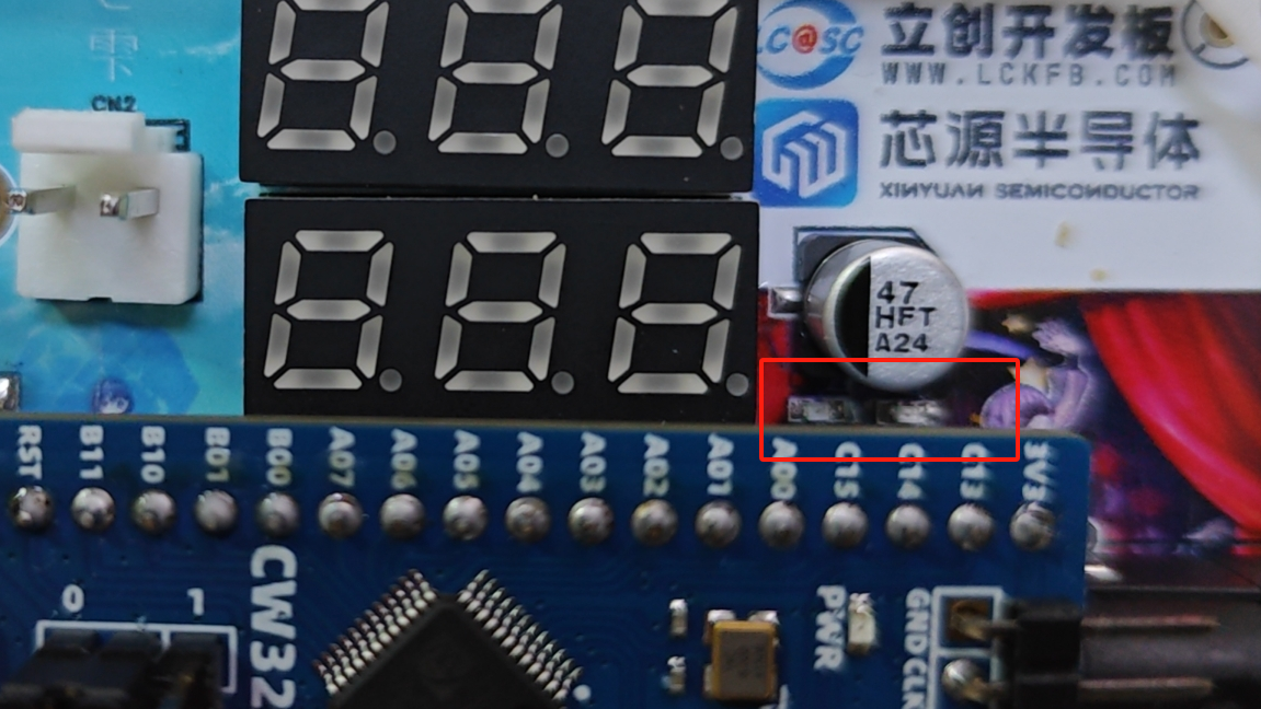 5. Software
  Ultimately, I only tested the voltage measurement function because I didn't have suitable wires for the current connection port. I used DuPont wires to connect the voltage measurement port and tested its functionality as shown in the video.

All reference designs on this site are sourced from major semiconductor manufacturers or collected online for learning and research. The copyright belongs to the semiconductor manufacturer or the original author. If you believe that the reference design of this site infringes upon your relevant rights and interests, please send us a rights notice. As a neutral platform service provider, we will take measures to delete the relevant content in accordance with relevant laws after receiving the relevant notice from the rights holder. Please send relevant notifications to email: bbs_service@eeworld.com.cn.
It is your responsibility to test the circuit yourself and determine its suitability for you. EEWorld will not be liable for direct, indirect, special, incidental, consequential or punitive damages arising from any cause or anything connected to any reference design used.
Supported by EEWorld Datasheet
EEWorld
subscription
account

EEWorld
service
account

Automotive
development
community

Robot
development
community

About Us Customer Service Contact Information Datasheet Sitemap LatestNews


Room 1530, 15th Floor, Building B,
No.18 Zhongguancun Street,
Haidian District,
Beijing, Postal Code: 100190
China
Telephone: 008610 8235 0740
 京公网安备 11010802033920号

 M295V100B-B70M6T


