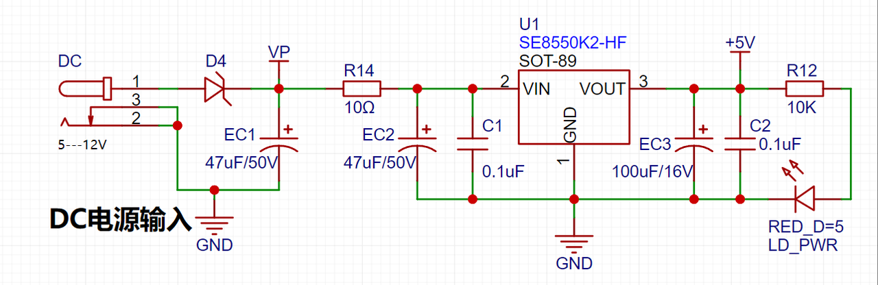
 uses an LDO as the power source. Considering that most voltmeter products are used in industrial scenarios with 24V or 36V power supplies, the SE8550K2 with a maximum input voltage of up to 40V was selected. The main reason for not using a DC-DC step-down circuit to handle the large voltage difference is to avoid introducing DC-DC ripple interference during the design process; a secondary reason is to reduce project costs.
  uses a 220K+10K voltage divider resistor, resulting in a voltage division ratio of 22:1 (ADC_IN11). The current
 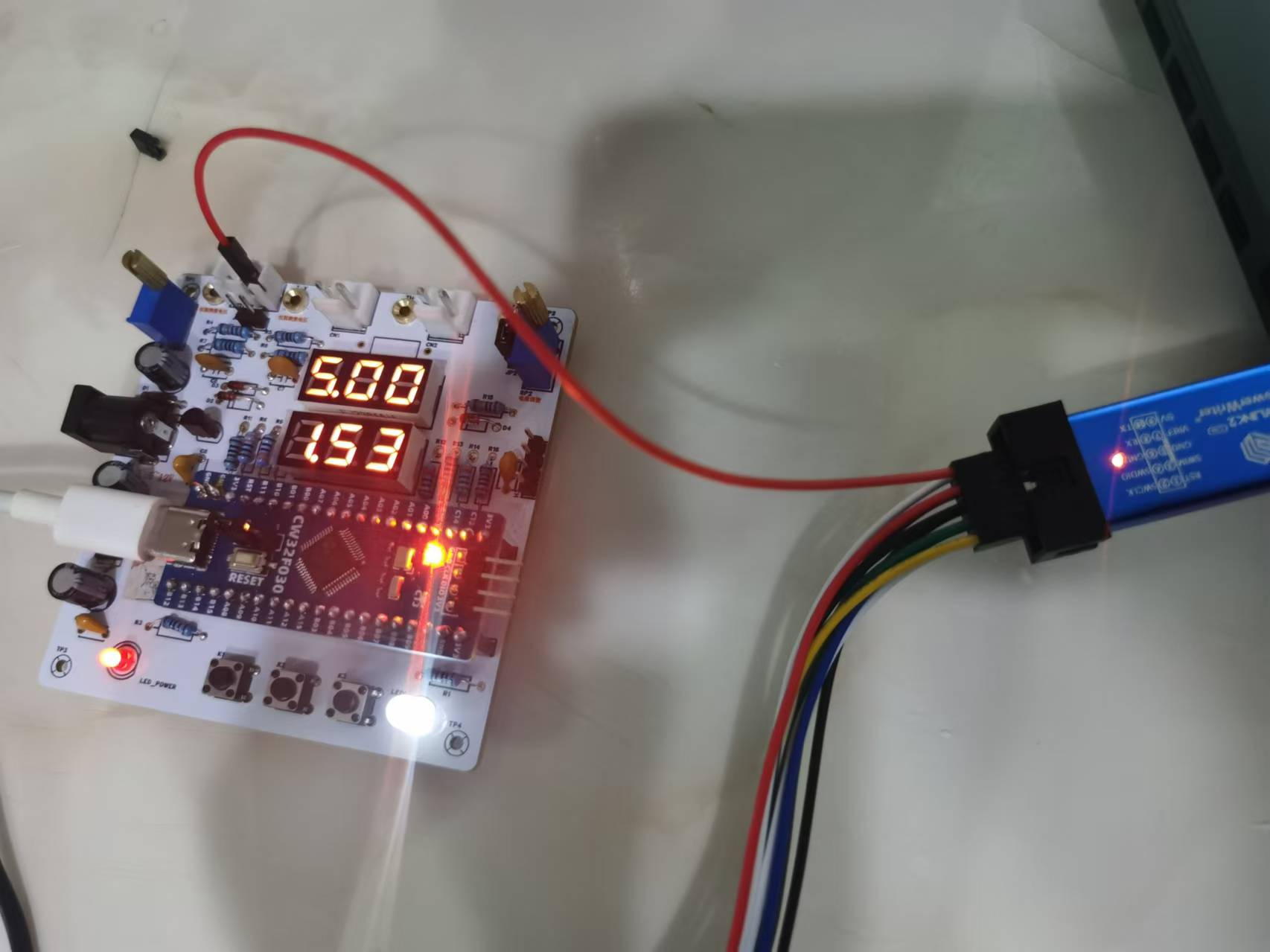 sampling
  uses a low-side current sampling circuit for current detection. The low-side of the sampling circuit shares a common ground with the meter interface on the development board.
 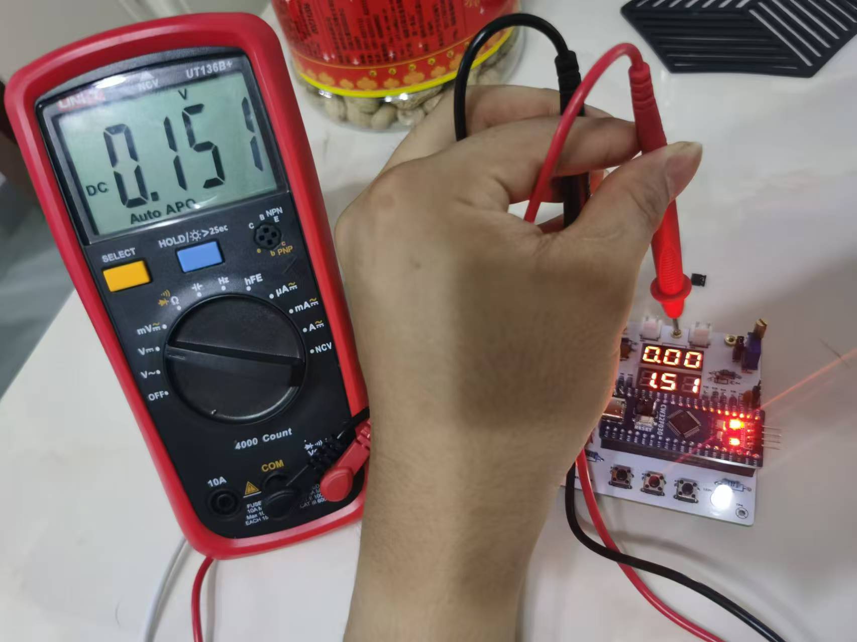 The digital tube driver
 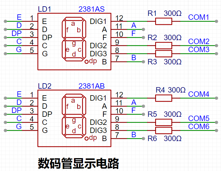 uses two 0.28-inch three-digit common-cathode digital tubes as display devices. Compared to displays, digital tubes have better visibility in complex environments. The brightness of the digital tubes can be increased by using smaller current-limiting resistors depending on the actual usage environment. Furthermore, digital tubes have better mechanical properties and are not easily damaged by external forces like displays. They are widely used in industrial applications requiring stability and reliability. From a development board learning perspective, it is easier to learn electronic measurement principles and related development in a targeted manner. An additional
  is added to provide a 2.5V reference voltage, which can be used to provide an external voltage reference for calibrating the AD converter. From a product design perspective, due to the inherent ADC performance advantages of the CW32, this circuit is not necessary. This circuit is designed on the development board to learn related application principles.
All reference designs on this site are sourced from major semiconductor manufacturers or collected online for learning and research. The copyright belongs to the semiconductor manufacturer or the original author. If you believe that the reference design of this site infringes upon your relevant rights and interests, please send us a rights notice. As a neutral platform service provider, we will take measures to delete the relevant content in accordance with relevant laws after receiving the relevant notice from the rights holder. Please send relevant notifications to email: bbs_service@eeworld.com.cn.
It is your responsibility to test the circuit yourself and determine its suitability for you. EEWorld will not be liable for direct, indirect, special, incidental, consequential or punitive damages arising from any cause or anything connected to any reference design used.
Supported by EEWorld Datasheet
EEWorld
subscription
account

EEWorld
service
account

Automotive
development
community

Robot
development
community

About Us Customer Service Contact Information Datasheet Sitemap LatestNews


Room 1530, 15th Floor, Building B,
No.18 Zhongguancun Street,
Haidian District,
Beijing, Postal Code: 100190
China
Telephone: 008610 8235 0740
 京公网安备 11010802033920号

 HF14FF/018-1HXXX


