I. Design Background
Learning to design and build a digital voltmeter and ammeter is highly beneficial for improving one's professional skills. The digital voltmeter and ammeter project covers multiple aspects, including microcontroller circuit design and implementation, signal acquisition and processing circuit design, user interface development and optimization, and product appearance design. It integrates knowledge from multiple fields such as electronics, microcontroller programming, circuit design, and industrial design. Considering the learning pace and knowledge absorption capacity of beginners, we have specially launched this introductory-level digital voltmeter and ammeter project, which is very suitable for beginners in electronics and those who want to learn more about microcontroller applications. This project has the following highlights:
it adopts a core board plus expansion board design concept and uses plug-in device design, making learning simpler and exploration more in-depth;
the core board uses the domestic Wuhan Xinyuan Semiconductor CW32 as the main controller, while also being compatible with other similar development boards; however, the CW32 has advantages.
This project is highly comprehensive and practical, and can be used as a desktop instrument after completion.
It offers abundant learning materials, including circuit design tutorials, PCB design, code programming, and training for engineers' debugging skills.
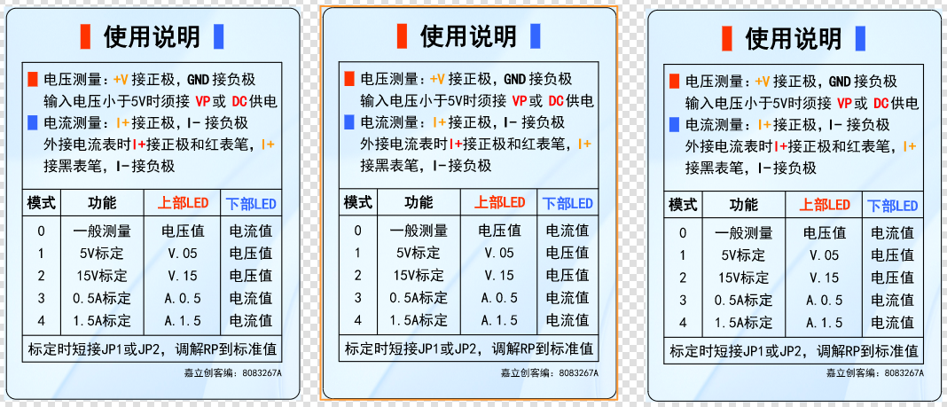
Instructions:
II. Hardware Design
1. Power Supply Circuit

2. Voltage Sampling Circuit
This project uses a voltage divider circuit to achieve high voltage acquisition. The design can acquire 100V, but the current configuration is 0-30V.
The voltage divider resistors are 220K+10K, therefore the voltage division ratio is 22:1 (ADC_IN11).
2. Current Sampling Circuit
This project uses a low-side current sampling circuit for current detection. When learning how to use the low-side sampling circuit and the development board's meter interface
, please do not solder R0!
Design Analysis:
The sampling current in this project is 3A, and the selected sampling resistor (R0) is 100mΩ.
The following aspects need to be considered when selecting the sampling resistor:
the maximum value of the pre-designed measurement current;
the voltage difference caused by the 3A current sensing resistor in this project;
and the power dissipation of the current sensing resistor, which should generally not exceed 0.5V. A suitable package should be selected based on this parameter. Considering the power dissipation (temperature) issue under high current, a 1W packaged metal wire-wound resistor was selected.
The voltage amplification factor across the current sensing resistor: No operational amplifier is used in this project to build the amplification circuit, so the factor is 1.
The current sensing resistor value can then be calculated using the above parameters
. Since no amplifier circuit is used, a larger sampling resistor is needed to obtain a higher measured voltage for measurement. However,
considering that a larger resistor would result in a larger voltage drop and higher power consumption, an unlimited selection of a larger resistor is not feasible.
This project uses a 1W package resistor, corresponding to a power consumption of 1W.
Based on the above data, a 100mΩ current-sensing resistor was chosen. According to the formula, 3A * 100mΩ = 300mV, 900mW.
To handle different operating environments, especially high-current scenarios, the R0 resistor can be replaced with constantan wire or a shunt. The appropriate alternative can be chosen based on the specific application scenario. For safety and educational purposes, this project will not discuss measurements exceeding 3A, but the principle remains the same.


 京公网安备 11010802033920号

 B3737
B3737


