Key advantages of
the CW32 in this project
: Wide operating temperature range: -40~105℃;
Wide operating voltage: 1.65V~5.5V (STM32 only supports 3.3V systems).
1. Power Supply Circuit
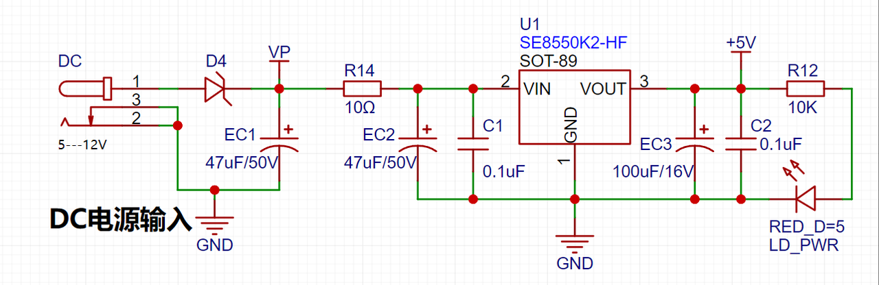
: LDO (Low Dropout Linear Regulator) Selection: This project uses an LDO as the power supply. Considering that most voltmeter products are used in industrial scenarios with 24V or 36V power supplies, the SE8550K2 with a maximum input voltage of 40V was selected. The main reason for not using a DC-DC step-down circuit to handle the large voltage drop is to avoid introducing DC-DC ripple interference during the design process; a secondary reason is to reduce project costs.
2. Voltage Sampling Circuit:
The voltage has two ranges: 0-3Vdc and 0-30Vdc.

In this project, an additional voltage sampling circuit was added. Therefore, we can discuss the significance of range switching for improving measurement accuracy. Multimeters often have multiple ranges to achieve more accurate measurements. By adjusting different ranges, the optimal measurement accuracy of the measured point within the corresponding range can be obtained.
This project requires a combination of hardware and software to achieve this function. When we first use the ADC_IN11 channel mentioned earlier to measure voltages within 30V, if the measured voltage is within 0~3V, then we use the ADC_IN9 channel for measurement. At this time, due to the reduced voltage division ratio, the measurement accuracy is greatly improved.
3. Current Sampling Circuit:
This project uses a low-side current sampling circuit for current detection. The low-side of the sampling circuit shares a common ground with the development board's meter interface.

5. Digital Tube Display:
This project uses digital tubes as the display unit.
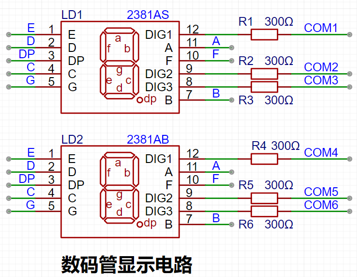
Two 0.28-inch three-digit common-cathode digital tubes are used as display devices. Compared to displays, digital tubes have better visibility in complex environments. Depending on the actual usage environment, smaller current-limiting resistors can be used to achieve higher brightness.
Furthermore, digital tubes have better mechanical properties and are not as easily damaged by external forces as displays. They are widely used in industrial applications requiring stability and reliability. From the perspective of learning from the development board, it is easier to learn electronic measurement principles and related development in a more targeted manner.
6. LED indicator
LD_PWR is the power indicator.

7. TL431 circuit design for voltage measurement and calibration:
This project adds an extra TL431 circuit to provide a 2.5V reference voltage. This can be used to provide an external voltage reference for the chip to calibrate the AD converter. From a product design perspective, due to the inherent ADC performance advantages of the CW32, this circuit is not necessary. This circuit is designed on the development board for learning related application principles.

Five operating modes are defined. The K1 key is used to switch display modes. The K2 key sets the parameter value for the corresponding mode and saves it to FLASH. The K3 key returns to mode 0.
Mode 0: Displays normal voltage and current values (the upper row of digital tubes displays the voltage value *.V or .*V automatically switching; the lower row displays the current value _.**A).
Mode 1: 5V voltage calibration value setting. (JP1 can be shorted to use the built-in voltage source for setting). The upper row of digital tubes displays 5.05. The lower row displays the current voltage value _.V or ._V. In this mode, the multimeter should be adjusted to 5.00V to measure the bit being measured. After pressing the K2 key, the current value is calibrated to a 5V voltage value.
Mode 2: 15V voltage calibration setting. (JP1 cannot be shorted) The upper row of the digital tube displays 5.15. The lower row displays the current voltage value _.V or ._V. In this mode, the multimeter should be set to 15.0V to measure the measured bit. After pressing the K2 key, the current value is calibrated to a 15V voltage value.
Mode 3: 0.5A current calibration setting. (JP2 can be shorted to use the built-in current source setting) The upper row of the digital tube displays A.0.5. The lower row displays the current current value _.**A. After pressing the K2 key, the current value is calibrated to a 0.5A current value.
Mode 4: 1.5A current calibration setting. (JP2 can be shorted to use the built-in current source setting) The upper row of the digital tube displays A.1.5. The lower row displays the current current value *.**A. After pressing the K2 key, the current value is set to 1.5A.
8. Enable System Clock
void RCC_Configuration(void)
{
/* 0. Enable and calibrate HSI */
RCC_HSI_Enable(RCC_HSIOSC_DIV6);
/* 1. Set the division coefficients of HCLK and PCLK */
RCC_HCLKPRS_Config(RCC_HCLK_DIV1);
RCC_PCLKPRS_Config(RCC_PCLK_DIV1);
/* 2. Enable PLL and multiply the frequency to 64MHz through PLL */
RCC_PLL_Enable(RCC_PLLSOURCE_HSI, 8000000, 6); // HSI default output frequency 8MHz
// RCC_PLL_OUT(); // Output PLL clock on PC13
///
///
__RCC_FLASH_CLK_ENABLE();
FLASH_SetLatency(FLASH_Latency_3);
/* 3. Switch the clock to PLL /*
RCC_SysClk_Switch(RCC_SYSCLKSRC_PLL);
RCC_SystemCoreClockUpdate(48000000);
RCC_PCLKPRS_Config(RCC_PCLK_DIV8); // Configure the frequency division factor from HCLK to PCLK to 6MHz
}
9. Timer Configuration
void Btim1_Init(void){ BTIM_TimeBaseInitTypeDef BTIM_TimeBaseInitStruct; __RCC_BTIM_CLK_ENABLE();
/* NVIC Configuration */ NVIC_EnableIRQ(BTIM1_IRQn);
BTIM_TimeBaseInitStruct.BTIM_Mode = BTIM_Mode_TIMER; BTIM_TimeBaseInitStruct.BTIM_Period = 6000 - 1; // Sample once every 1ms BTIM_TimeBaseInitStruct.BTIM_Prescaler = BTIM_PRS_DIV1; // 6MHZ BTIM_TimeBaseInitStruct.BTIM_OPMode = BTIM_OPMode_Repetitive;
BTIM_TimeBaseInit(CW_BTIM1, &BTIM_TimeBaseInitStruct); BTIM_ITConfig(CW_BTIM1, BTIM_IT_OV, ENABLE); BTIM_Cmd(CW_BTIM1, ENABLE);
Note: The video current display is incorrect because resistor R0 is not connected.


 京公网安备 11010802033920号

 2200RAG600JF3FA


