I. Project Function Introduction
The core board used in this project is the domestically produced Wuhan Xinyuan Semiconductor CW32 as the main controller. Combined with its 12-bit high-speed ADC and multiple VREF reference voltages, it enables the measurement of voltage and current during USB operation or the current of the device under test, which is then displayed via a digital tube.
Furthermore, based on specific usage requirements, USB-TTL communication, lithium battery charging, and OLED display functions (reserved) have been added.
II. Hardware Design
1. Power Supply Circuit
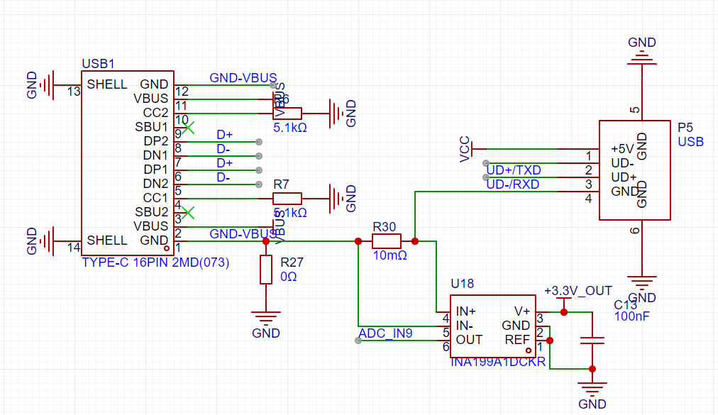
Considering that voltage measurements during development typically use a multimeter, and to maximize the usability of the product and prevent it from becoming unused, the recommended LDO wide voltage input method was not adopted. Instead, a USB-5V power supply was used, which is compatible with both the frequently used USB-A and USB Type-C interfaces.
2. MCU Selection Analysis - Key Advantages of CW32 in this Project:
Wide Operating Voltage: 1.65V~5.5V;
Better ADC: 12-bit high-speed ADC, achieving ±1.0LSB INL 11.3ENOB; Multiple Vref Reference Voltages.

3. Voltage Sampling Circuit Voltage
Divider Resistor Selection:
USB communication voltage is generally 5V. The maximum voltage to be measured in this project is 30V for safety reasons.
The ADC reference voltage is 1.5V in this project.
To reduce power consumption in the sampling circuit, the low-side resistor is typically chosen as 10K based on experience.
The high-side resistance of the voltage divider is calculated using the above parameters
. The required voltage division ratio is calculated as follows: ADC reference voltage: Design input voltage, which can be calculated as 1.5V/30V = 0.05 using known parameters.
High-side resistance: Low-side resistance/voltage division ratio, which can be calculated as 10K/0.05 = 200K using known parameters.
A standard resistor is selected: A resistor slightly higher than the calculated value of 200K is chosen. We typically choose E24 series resistors; therefore, in this project, 220K is selected, which is greater than 200K and closest to the calculated value.
4. Current Sampling Circuit
The current sampling circuit here is divided into two parts: USB-powered current measurement and external device current measurement
.
USB-powered current measurement: This circuit design is based on the #7th LCSC Electronics Design Contest# USB ammeter, with some adjustments. The current sampling part uses the INA199A1DCKR current sensing amplifier (also known as a current sensing amplifier), commonly used for overcurrent protection, precision current measurement optimized for systems, or closed-loop feedback circuits. This series of devices can sense the voltage drop across a shunt resistor from –0.3V to 26V common-mode voltage, independent of the supply voltage. Three fixed gains are available: 50V/V, 100V/V, and 200V/V. The INA199A1DCKR current sensing amplifier selected for this project has a gain of 50V/V.
Sampling Resistor Selection
: Inserting a low-resistance sensing resistor in series in the current path creates a small voltage drop, which can be amplified and used as a signal proportional to the current. However, depending on the specific application environment and the location of the sensing resistor, this technique will present different challenges to the sensing amplifier. Generally, sampling resistors have a resistance value below 1 ohm, belonging to the milliohm level of non-inductive resistors. However, some resistors, due to sampling voltage requirements, must be selected with a larger resistance value, but a larger resistance base results in a larger error. This project uses a 10mΩ sampling resistor.
The sampling method
used here is low-side sampling, meaning the sampling resistor is connected to the GND circuit. This design allows for complete differential, follow-up, amplification, and output operations when the differential signal is fed into the op-amp. If high-side sampling is used, where the sampling resistor is placed high between the power supply and the load, although this placement not only eliminates ground interference generated in low-side detection schemes but also detects accidental short circuits from the battery to system ground, high-side detection requires the detection amplifier to handle common-mode voltages close to the power supply voltage. This common-mode voltage range is wide, from the level required for monitoring the processor core voltage (approximately 1V) to several hundred volts common in industrial, automotive, and telecommunications applications. Application examples include typical laptop battery voltages (17 to 20V), 12V, 24V, or 48V batteries in automotive applications, 48V telecommunications applications, high-voltage motor control applications, current sensing for avalanche diodes and PIN diodes, and high-voltage LED backlighting. Therefore, a significant advantage of high-side current sensing is the ability of the sense amplifier to handle larger common-mode voltages. Thus, the current sampling method using a sampling resistor and operational amplifier is best performed at the low end. Although low-side sampling can affect signal ripple due to ground interference, it is simpler, less expensive, and more reliable than high-side sampling.
The measured current is 3A: 3A * 10mΩ * 50 = 1500mV = 1.5V.
For external device current measurement,
the sampling current designed for this project is 3A, and the selected sampling resistor (R0) is 100mΩ. The selection of the sampling resistor mainly needs to consider the following aspects:
the maximum value of the pre-designed measurement current, which is 3A in this project;
the voltage difference caused by the current sensing resistor, which is generally not recommended to exceed 0.5V;
the power consumption of the current sensing resistor, and a suitable package should be selected based on this parameter. Considering the power consumption (temperature) problem under high current, a 2W low-resistance alloy current sampling chip resistor was selected in this project;
the amplification factor of the voltage across the current sensing resistor: no operational amplifier was used to build the amplification circuit in this project, so the factor is 1;
the measured current is 3A: 3A * 100mΩ = 300mV.

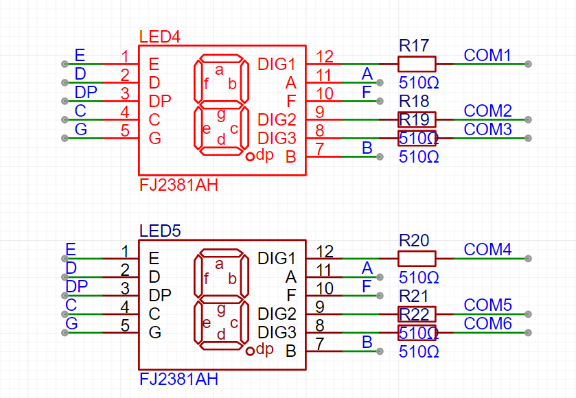
5. Digital tube display:
This project uses a digital tube as the display unit.
This project uses two 0.28-inch three-digit common-cathode LED displays as the display device. Compared to displays, LED displays offer better visibility in complex environments. The brightness of the LED displays can be increased by using smaller current-limiting resistors to meet the specific needs of the application environment. Furthermore, LED displays have better mechanical properties and are not as easily damaged by external forces as displays. They are widely used in industrial applications where stability and reliability are crucial.
The driving principle of LED displays
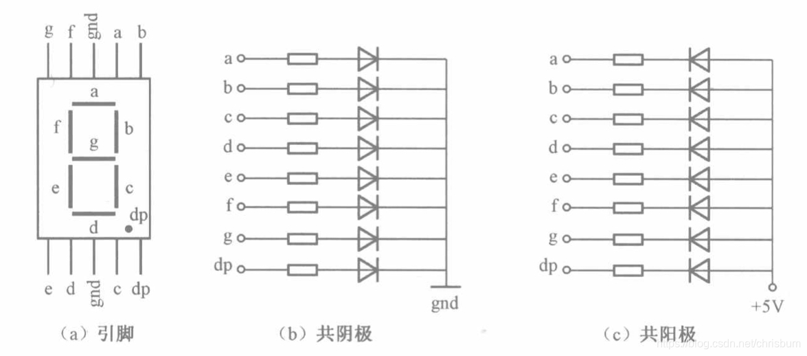
: The basic structure of an LED display:
LED displays typically consist of seven or eight LED segments (eight segments in this project). Each segment represents a part of the display and can display numbers 0-9, letters AF, etc.
LED displays come in two types: common cathode and common anode. The difference lies in whether the common terminal COM (connecting all LEDs) is connected to the negative or positive terminal of the power supply.
Driving method:
Segment selection: The desired number or character is displayed by controlling the on/off state of each segment of the LED display. Each segment corresponds to a control signal; when the control signal is on, the segment lights up, and vice versa. (a, b, c, d, e, f, g, dp)
Bit Selection: The desired display segment is selected by controlling the bit lines of the LED display. Bit line control sets the bit line of the desired segment to a high level and the bit lines of other segments to a low level. By continuously switching the state of the bit lines, display switching between multiple LEDs can be achieved.
Driving Circuit:
The LED display driving circuit can be implemented using hardware circuits, such as integrated circuits like digital signal processors (DSPs), microcontrollers (MCUs), or shift registers to generate control signals suitable for the LEDs.
These control signals can be in the form of pulse width modulation (PWM) signals, serial data signals, etc. By controlling the frequency, width, and amplitude of these signals, the brightness of the digital tube can be controlled, thereby displaying the desired numbers or letters.
Software control:
In addition to hardware drive circuits, digital tubes can also be driven by software control. By programming to generate control signals suitable for the digital tube, more flexible and complex display effects can be achieved, such as scrolling or alternating display of numbers.
Driving common cathode and common anode digital tubes:
For common cathode digital tubes, the common cathode pin is connected to the negative terminal of the power supply, and the control pin is connected to the output pin of the control chip. When a certain number needs to be displayed, the control chip outputs the corresponding encoded signal to the control pin, causing the corresponding LED segment to light up.
For common anode digital tubes, the working principle is similar to that of common cathode digital tubes, except that the common anode pin is connected to the positive terminal of the power supply, and the control pin is connected to the output pin of the control chip.
Encoded display:
In order for the digital tube to display the corresponding numbers or characters, the segment data port must output the corresponding character encoding. For example, to display the number "0", the character code for a common anode seven-segment display is 11000000B (i.e., C0H), while the character code for a common cathode seven-segment display is 00111111B (i.e., 3FH). The specific code depends on the actual seven-segment display.
Dynamic and Static Display:
Seven-segment displays can use either static or dynamic display methods. In static display, each of the eight segments of each seven-segment display is connected to an 8-bit I/O port address. As long as the I/O port outputs a segment code, the corresponding character is displayed and remains unchanged. Dynamic display, on the other hand, lights up each segment of the seven-segment display one by one, achieving simultaneous visual display through rapid switching.
In summary, the driving principle of seven-segment displays is to control the switching state of each segment of the seven-segment display to display numbers, letters, or symbols, and to achieve display switching between multiple seven-segment displays through segment selection and digit selection. Furthermore, the driving of seven-segment displays can be implemented through hardware circuits or software control, and common cathode or common anode seven-segment displays can be selected as needed.
This project actually uses dynamic scanning display to drive the seven-segment display.
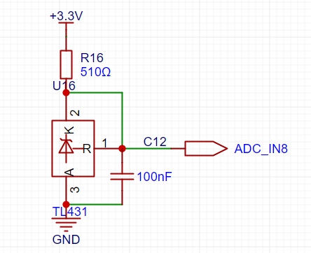
6. TL431 Circuit Design for Voltage Measurement Calibration:
This project adds an additional TL431 circuit to provide a 2.5V reference voltage. This can be used to provide an external voltage reference for the chip to calibrate the AD converter; this function is reserved.
The TL431 is named a precision programmable reference, and its accuracy is vastly different from common Zener diodes. The adjustable output voltage is from Vref to 36V. The sink current capability is highly dependent on the resistance value in the application circuit. It should not be less than 1mA. If there is no need for sink current, do not design the current too high, as this will cause unnecessary power consumption.
II. Software Design
The software primarily uses and modifies the official example code. It automatically adjusts the measurement range based on the measured current value:
when the current > 1A, it displays X.XX (current unit is A);
when 1A > 0.1A, it displays XXX (current unit is mA);
when 0.1A > current, it displays XX.X (current unit is mA).

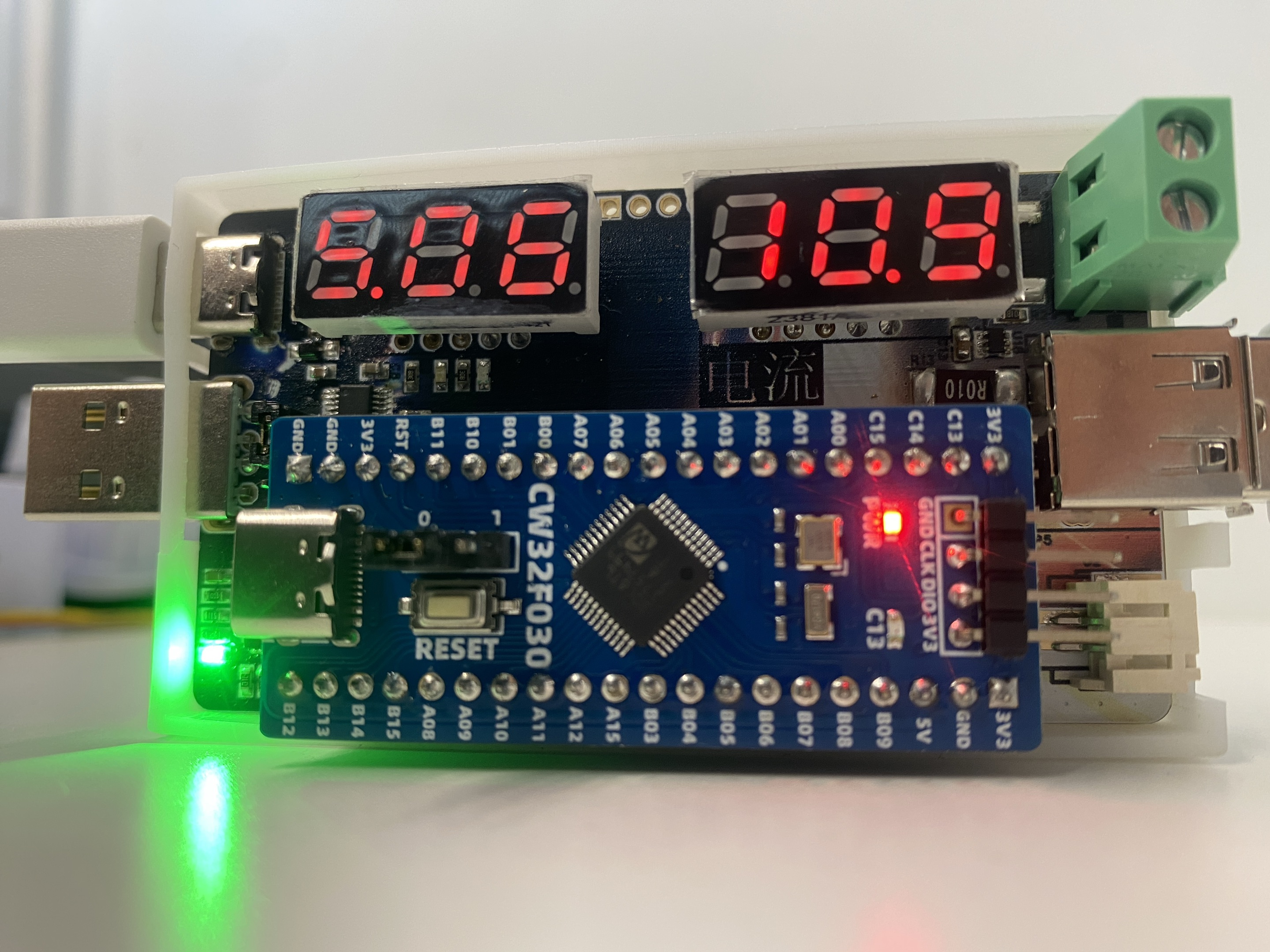
The following is a demonstration of the effect:
when the current > 1A, it displays X.XX (current unit is A);
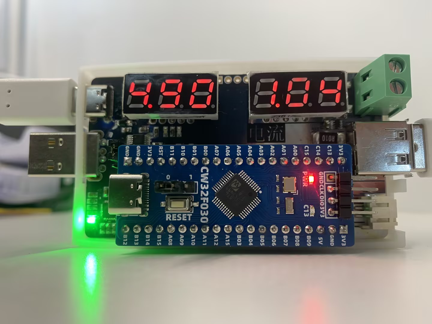
when 1A > 0.1A, it displays XXX (current unit is mA);

when 0.1A > current, it displays XX.X (current unit is mA).


 京公网安备 11010802033920号

 1N5238BRL


