This project introduces a convenient environmental monitoring instrument designed by LCSC Liangshanpai. Its
functions include
: 1. Collecting parameters such as temperature, humidity, atmospheric pressure, and harmful gases;
2. Displaying this information via LVGL;
3. Uploading the collected information to the Alibaba Cloud platform via an NBIoT module, and allowing real-time viewing via a mobile app
; 4. Sending the collected information to a slave device for display via the NF-03 wireless module; and
5. Implementing a human-machine interface via LVGL. The hardware
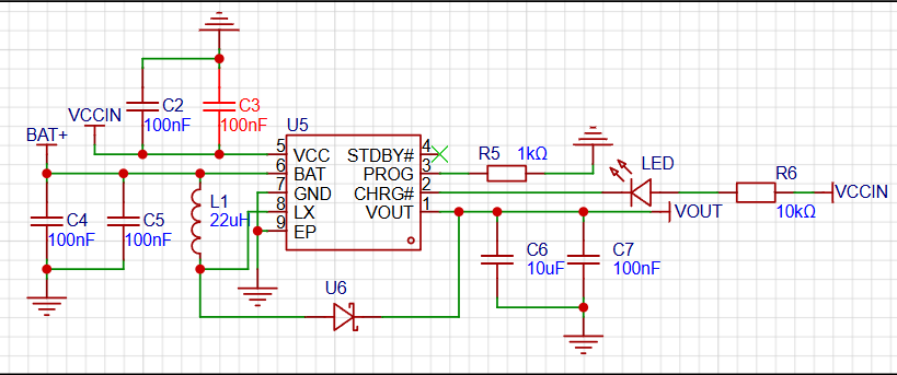
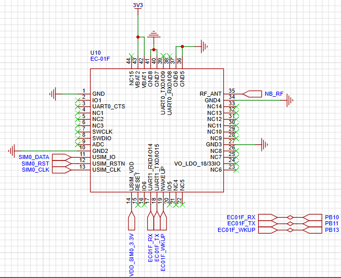
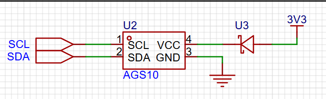
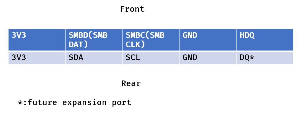
design utilizes the TP5400 lithium battery charging and boost control chip. The TP5400 is a dedicated single-cell lithium-ion battery charger and constant 5V boost controller for power banks. The charging section integrates high-precision voltage and charging current regulators, pre-charging, charging status indication, and charging cutoff functions, and can output a maximum charging current of 1A. The NF-03 wireless module used in this project is designed by Aisinco Technology. The NF-03 is a 5mW 2.4G transceiver module. A 2.4G module is used for wireless communication, enabling wireless data transmission and reception in the 2.4GHz band. This module typically consists of a transceiver and related control circuitry, providing users with a convenient wireless communication solution. The NB-IoT module used in this case is the EC-01F. The EC-01F is an NB-IoT module developed by Aisinco Technology. The NB portion uses the EC616S as its main chip. This chip features a highly integrated NB-IoT SoC, supports ultra-low power consumption, and fully supports the 3GPP Rel14 NB-IoT standard, making it a high-performance NB-IoT chip. Temperature and humidity sensors are devices used to measure ambient temperature and relative humidity. They typically consist of a sensing element, signal processing circuitry, and an output interface. Common sensing element technologies include thermistors, capacitive humidity sensors, and semiconductor sensors. Thermistors measure temperature based on the material's temperature sensitivity, while capacitive humidity sensors measure humidity using the relationship between humidity and capacitance. Semiconductor sensors can measure both temperature and humidity, making them multifunctional sensors. This case study uses the AHT21 temperature and humidity sensor. As a new generation of temperature and humidity sensors, the AHT21 sets a new standard in size and performance: it is embedded in a dual-in-line flat no-leads SMD package suitable for reflow soldering, with a bottom area of 3x3mm and a height of 0.8mm. The sensor outputs a calibrated digital signal in standard I2C format. Barometric pressure sensors are widely used in meteorological observation, climate research, air quality monitoring, aircraft navigation and altitude measurement, and barometric pressure control systems. They provide real-time and accurate barometric pressure data, helping people understand and predict weather changes and achieve precise altitude measurement and control. This case study uses the WF183D digital waterproof barometric pressure sensor. The WF183D is an economical digital pressure and temperature sensor that internally contains a MEMS pressure sensor, a high-resolution 24-bit ΔΣADC, and a DSP. The WF183D provides high-precision calibrated digital pressure and temperature outputs via UART, and communication connections are very simple. This case study utilizes the AGS10 TVOC sensor, a MEMS TVOC sensor with digital signal output. It incorporates dedicated digital module acquisition technology and gas sensing technology, ensuring extremely high reliability and excellent long-term stability. It also features low power consumption, high sensitivity, fast response, low cost, and a simple drive circuit. The AGS10 is primarily suitable for detecting various volatile organic compounds, such as ethanol, ammonia, sulfides, benzene vapors, and other harmful gases, and can be applied in air purifiers, home appliances, and fresh air systems. Sensor Characteristics: The sensor uses the standard IIC communication protocol, adaptable to various devices. The IIC physical interface includes two interfaces: serial data signal (SDA) and serial clock signal (SCL). During design, both interfaces need to be pulled up to VDD through 1kΩ to 10kΩ resistors.


Demonstration video.mp4
Environmental monitor.zip
PDF_Environmental Monitoring Instrument.zip
Altium_Environmental Monitoring Instrument.zip
PADS_Environmental Monitoring Instrument.zip
BOM_Environmental Monitoring Instrument.xlsx
91845
[FOC] A simple FOC ESC
This is a simple sensor-driven FOC driver for a gimbal motor, implementing torque control. The software only implements basic SVPWM and fixed-point current loops, allowing for further development. The main controller is an AT32F421, the phase current detection IC is an INA240A1, and the angle sensor is an AS5600.
Edited October 1, 2024:
Happy National Day!
1. The small output capacitors (C16, C25) on the two bulk power supplies (U4 and U11) should not be labeled. Because this bulk is a COT power supply, small-capacity mlcc capacitors will oscillate in the circuit. (It exploded twice.)
2. The motor experiences significant interference during operation. Specifically, spikes appear on the 12V power supply and the PWM signal output by the microcontroller. If a higher-power motor is replaced later, the interference will be even greater. The preliminary solution is to add more 100nF filter capacitors to the bus and move the 12V power supply to the power input port.
3. This is the first time the code is being released. The code follows the GPL3.0 open-source license. The code implements unidirectional rotation and six-step commutation functions for the sensor-controlled fork in the circuit. The six-step commutation function was not tested on the gimbal motor, but only on a model aircraft motor.
==================The following is the main text===================
I am interested in FOC. Adhering to the principle of "knowing something requires doing it," I designed my own FOC hardware and software system. The following is the main diagram:
Hardware: The main controller uses an AT32F421, CM4 core, 120MHz main frequency; the phase current sampling IC is an INA240A1; the angle sensor is an AS5600; the power stage uses an EG3116 pre-driver + 042N10N, with sufficient power margin. The motor used is a gimbal motor purchased from Xianyu (a second-hand marketplace).
Software: It implements 6-step commutation (to verify the hardware design), full fixed-point SVPWM generation, current loop PID, and Clarke/Park transformation (only multiplication and addition, shifting instead of division), with high performance.
The SVPWM generation method in this project references articles https://zhuanlan.zhihu.com/p/414721065 and
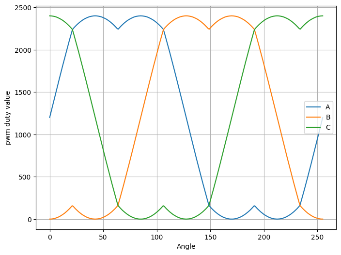
https://zhuanlan.zhihu.com/p/303998608, and we thank these two authors for their selfless contributions. In this project, the sine and cosine values of the angles are obtained using a lookup table method, with an angle resolution of 8 bits. During calculation, the trigonometric function values are multiplied by 8192 (2^13) beforehand, and then shifted right by 13 bits when calculating the timer value. A similar operation is used when performing Clarke transformation and PID. This maximizes accuracy, and since the calculations only involve multiplication and addition, the efficiency is high. The following figure shows the SVPWM timer values generated using the fixed-point method. The horizontal axis represents the angle, and the vertical axis represents the timer value of the PWM duty cycle.
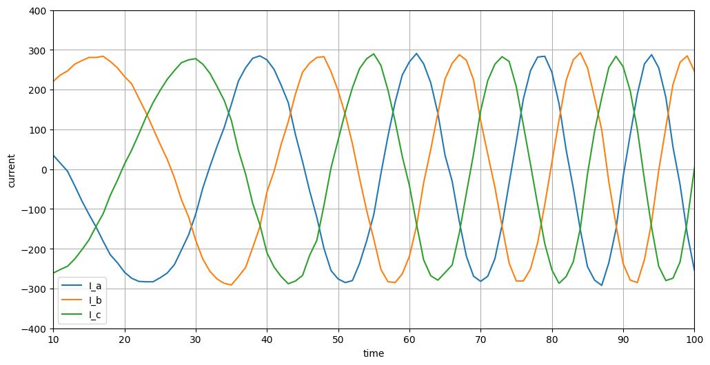
The output phase current waveform is shown in the following figure. The phase current value is output via serial port, and the waveform is quite perfect (although high-frequency components may be lost due to the slow serial port speed). The microcontroller-side control sampling timing is the midpoint of the PWM cycle (center-aligned PWM).
Finally, the software for this project is still under development. Currently, only basic rotation has been implemented, and it will require further refinement before it can be open-sourced.
at32_foc.zip
PDF_【FOC】A Simple and Thoughtful FOC ESC.zip
Altium_【FOC】A Simple and Thoughtful FOC ESC.zip
PADS_【FOC】A Simple and Engaging FOC ESC.zip
BOM_【FOC】A Simple and Engaging FOC ESC.xlsx
91846
Infrared thermal imager based on LCSC development board
This infrared thermal imager is built using the AMG8833 thermal imaging module on the LCSC GD32E230 development board. It is powered by a rechargeable lithium battery, continuously refreshes the temperature cloud display, allows one-click locking of the captured infrared thermal image, one-click display of the hottest temperature points, and one-click standby screen-off. It also includes a host computer display.
Project Introduction:
Infrared thermal imaging can detect temperature changes that are imperceptible to the human body, making it a very useful electronic product, particularly in areas such as circuit fault repair, biological sensing, and overheat detection. However, commercially available thermal imaging devices are generally expensive, costing hundreds or even thousands of yuan. Therefore, a low-cost solution is needed for personal daily use. This project aims for low cost and modularity, using the AMG8833 infrared thermal imaging module combined with the GD32E230 LCSC development board to create this infrared thermal imager. Aside from the infrared thermal imaging module costing approximately 90 yuan, the remaining hardware costs were less than 30 yuan thanks to a coupon issued by LCSC.
Project Function
1: Refreshing the Infrared Thermal Imaging Screen.
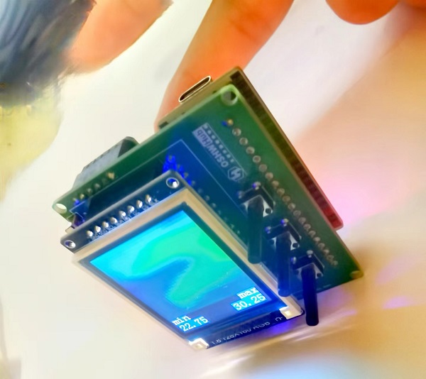
Simply plug the USB cable into the LCSC development board or turn on the built-in lithium battery to power on the infrared thermal imager. After initialization, it automatically refreshes and displays the infrared thermal imaging screen, as shown in the image below. A finger placed in front of the infrared thermal image will display a colored outline of its temperature; bluer indicates a lower temperature, and redder indicates a higher temperature. The lowest and highest temperatures of the currently detected image are displayed in the lower left and lower right corners of the screen, respectively.

2. Fixing the Infrared Thermal Imaging Image:
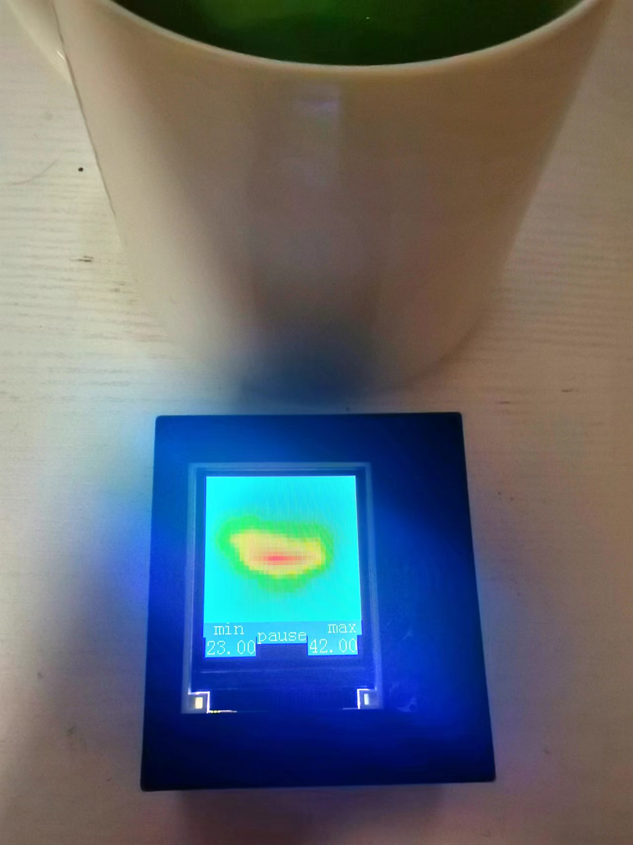
Sometimes we want to fix the thermal imaging image for better viewing. To do this, press the first button on the right side of the screen until "pause" appears at the bottom of the screen, indicating the infrared thermal imaging image is now fixed. As shown in the image below, after pointing the infrared thermal imager at the hot water cup, press the first button to fix the image. In the "pause" state, you can move the imager to point it at other locations; the image will stop refreshing until you press the first button again. The "pause" message at the bottom of the screen will disappear, and the image will resume refreshing.
3. Displaying the Highest Temperature Point:
While the screen is normally refreshing and displaying the infrared thermal imaging image, press and hold the second button on the right side of the screen. A white crosshair with a red background will appear on the screen. The position of this crosshair is the highest temperature point in the entire thermal imaging image. Moving the imager will move the crosshair back to the location of the highest temperature point. As shown in the following figure:

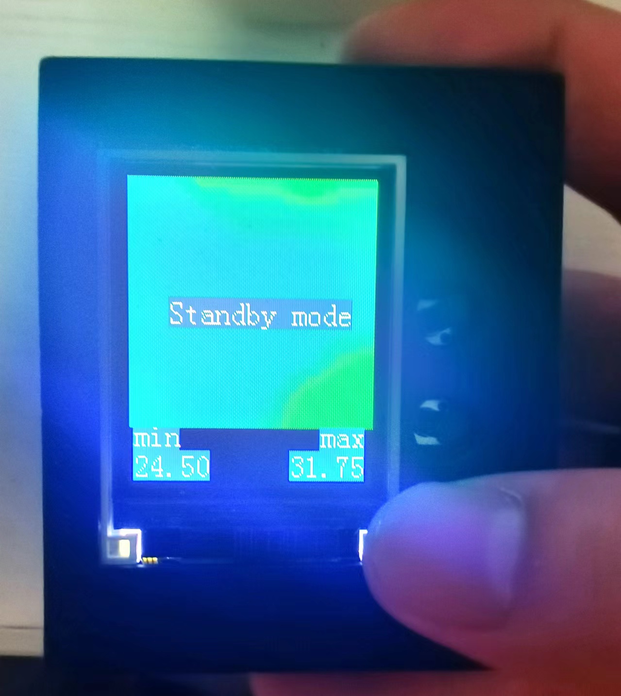
4: Long press the button to turn off the screen.
When charging or temporarily not in use, press and hold the third button on the right side of the screen until "Standby mode" appears, then release to turn off the screen. The development board enters standby mode, and power consumption drops to the μA level. It can be woken up again by using the power switch on the left or by powering on again.
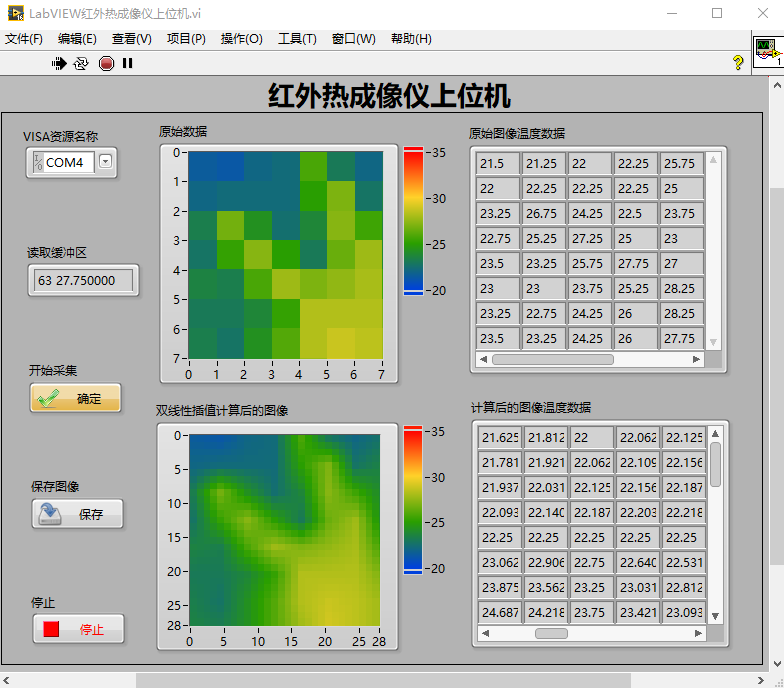
5: Real-time acquisition, display, and saving
of infrared thermal imaging images by the host computer. The Type-C port of the development board can not only provide power but also transmit temperature field data. Connect the other end of the Type-C port (USB port) to the computer. When the infrared thermal imager refreshes and displays the infrared thermal image, the computer's serial port simultaneously receives the real-time temperature data from 64 points (because the AMF8833 is an 8x8 infrared thermometer, it returns 64 temperature field data points each time it acquires data). The author developed a LabVIEW-based host computer for the infrared thermal imager, as shown in the following figure. The host computer can display the raw acquired data and the data and images calculated by bilinear interpolation in real time. In addition, it can save the thermal imaging images as BMP files to the computer separately.
Project Parameters:
This design uses the AMG8833 infrared thermal imaging module as the infrared thermal imaging sensor, which can transmit 8x8 temperature field data in a single transmission via IIC communication. A
1.8-inch 128x160 RGB TFT display module is used to display the infrared thermal imaging image and temperature minimum and maximum values in real time.
A lithium battery charging/discharging module with a 180mAh lithium battery is used for power supply.
The design is based on the LCSC GD32E230C8T6 development board as the main control chip board, with the Type-C port on the development board used for power supply and communication.
An SD card module is reserved, which can later communicate with the development board via the SPI protocol to store the infrared thermal imaging image to the memory card.
This design is compatible with LabVIEW host computer, which can be installed with NI-VISA and runs normally in version 2016 and above.
Principle Analysis (Hardware Description)
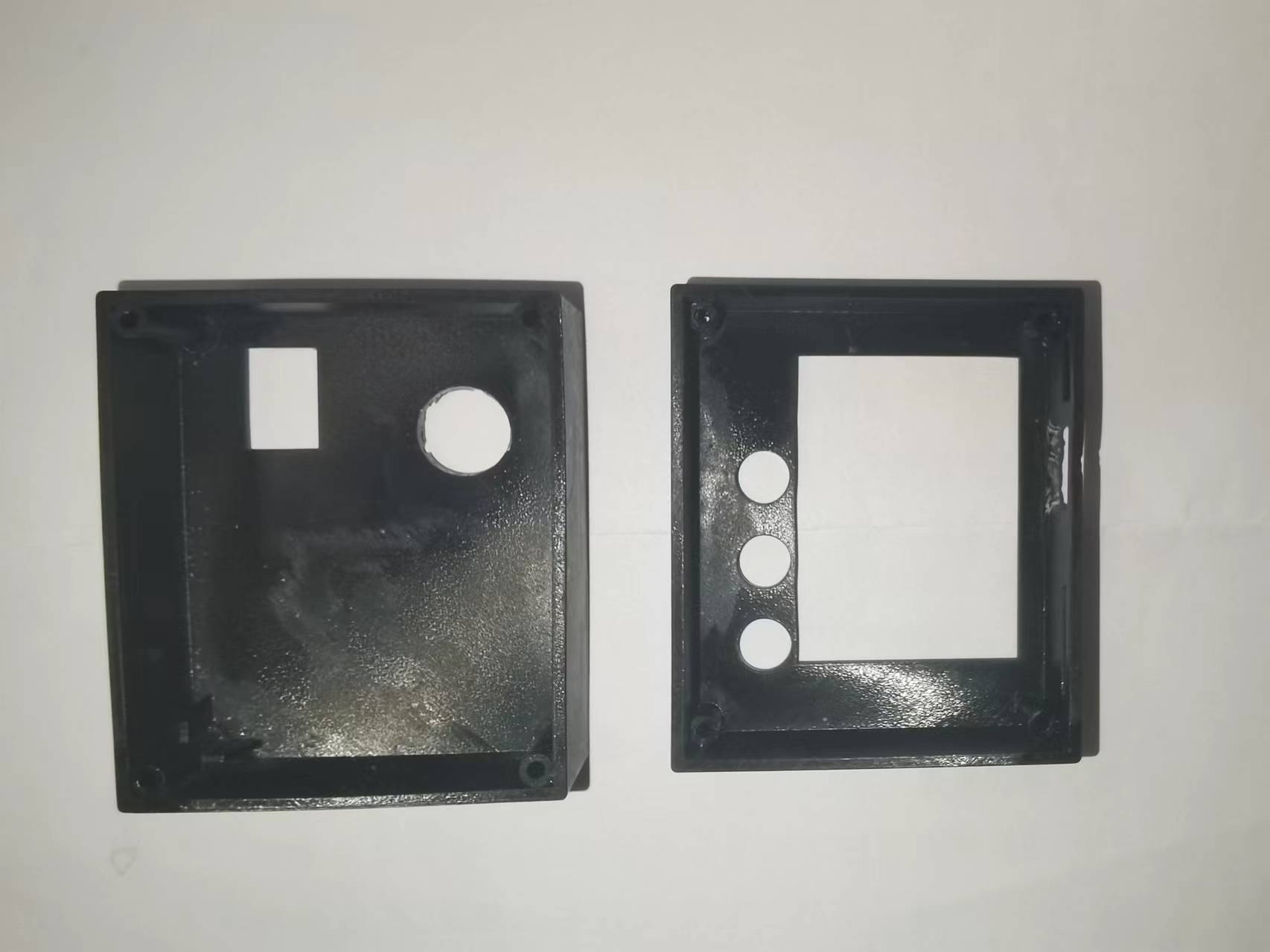
This project adopts a modular design, divided into a back layer, a front layer, and a middle layer.
The back layer, as shown in the diagram, houses the AMG8833 infrared thermal imaging module (hardware cost approximately 90 RMB), the lithium battery, and the development board module (hardware cost 9.9 RMB).

The front layer, as shown in the diagram, houses the display module and three long-handled button control modules.

Removing the display module reveals the middle layer, as shown in the diagram, which contains the lithium battery charging/discharging module, the SD card module, and the power switch. Power is supplied
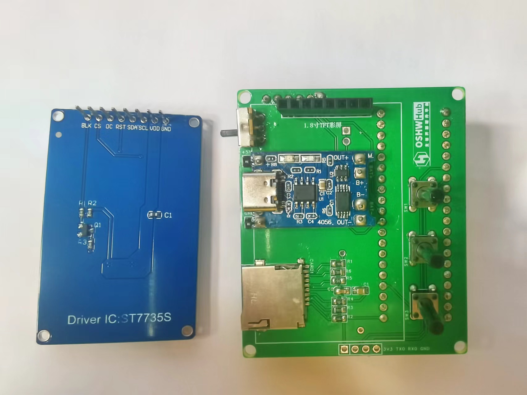
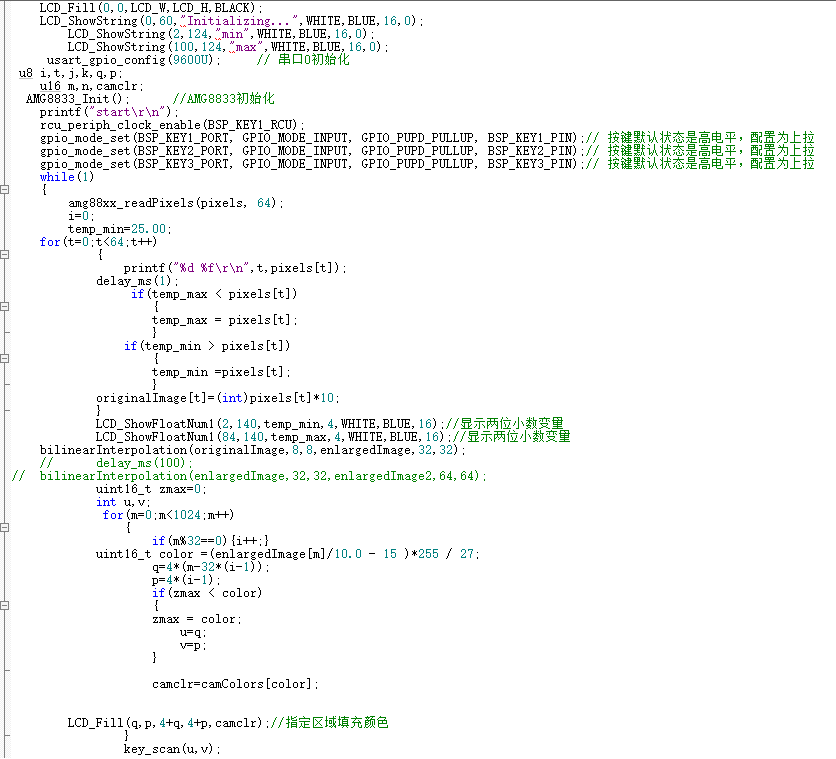
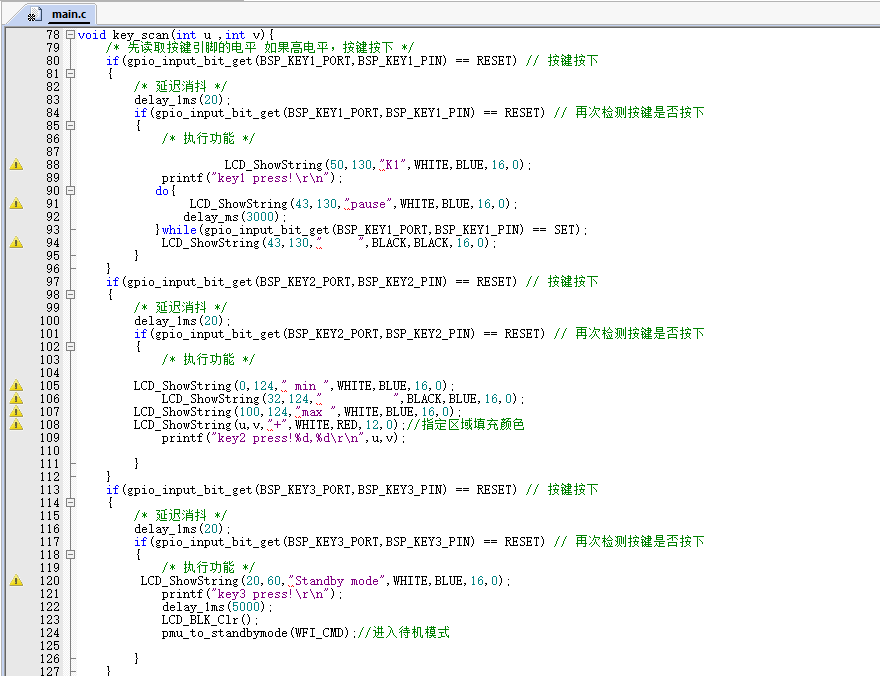
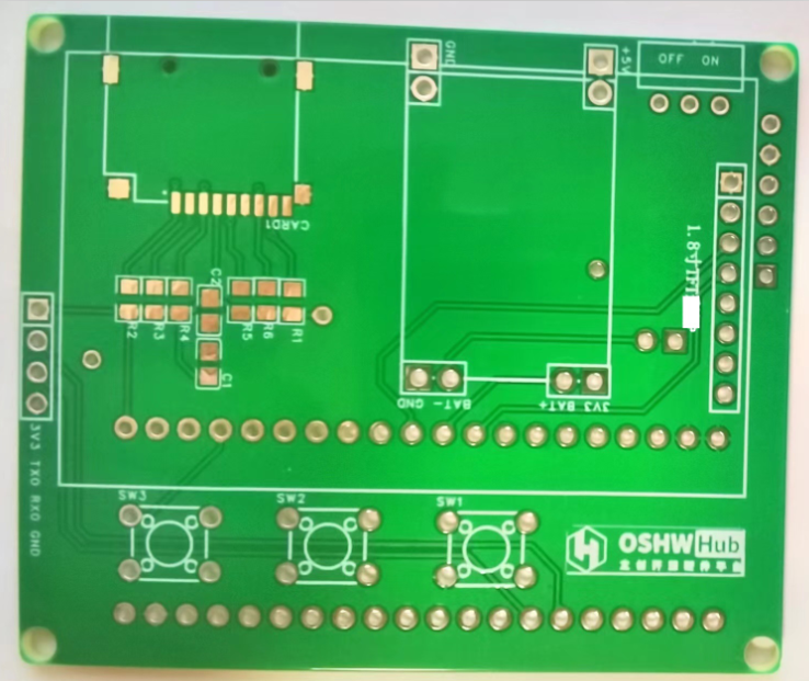
via the lithium battery and its charging/discharging module or a Type-C port. The power switch controls whether the lithium battery is connected to the circuit. The three buttons control the display and interaction with the infrared thermal imager. The LCSC development board serves as the main control board. Software Code The core code of this project displays and sends the data collected by the infrared thermal imaging module, and handles user interaction. Infrared thermal imaging data acquisition, processing, display, and transmission code: The button control interaction logic code is as follows: Links to some of the code referenced in this project are as follows: AMG8833 8x8 thermal imaging sensor_amg8833 Chinese datasheet ; C language implementation code for bilinear interpolation function. Important notes: When soldering pin headers and sockets, the hot air gun temperature should not be set too high. Excessive temperature can cause unmelted solder to flow through the holes to the other side of the PCB, causing a short circuit between two adjacent drilled holes! When charging the lithium battery, press the third button to enter standby mode to reduce power consumption. A hole needs to be made on the back of the casing to prevent the development board's pin headers from interfering with the back casing. Additionally, the side USB hole should be flush with the side opening during soldering; otherwise, the charging interface will be interfered with by the casing, preventing the charging cable from being inserted. The assembly process involves soldering surface-mount components, such as the pull-up resistors, capacitors, and SD card slot for the SD card module. Next, solder headers, sockets, and through-hole components, such as buttons, lithium battery charging/discharging modules, display sockets, development board sockets, and infrared thermal imaging module sockets (so that the sockets can be easily removed from the corresponding modules). Finally, insert the display, infrared thermal imaging module, and development board into their respective sockets. The front view of the hardware PCB for this project is shown below. The back view of the hardware PCB for this project is shown below. In addition, this project also designed corresponding upper and lower housings, as shown in the following figures. After the PCBA is completed, the bare device is placed inside the housing and secured with thin screws. The assembled device and its usage are shown below: Bare device without housing: Hardware measurement with housing: Finally, thank you for your support, JLCPCB. This project may have shortcomings; please leave comments for discussion. Thank you.


LabVIEW Infrared Thermal Imager Host Computer.vi
Infrared thermal imager lower-level machine Keil source code.zip
Infrared thermal imager demonstration.mp4
PDF_Infrared Thermal Imager Based on LCSC Development Board.zip
Altium_Infrared Thermal Imager Based on LCSC Development Board.zip
PADS_Infrared Thermal Imager Based on LCSC Development Board.zip
BOM_Infrared Thermal Imager Based on LCSC Development Board.xlsx
91847
Windows Hello fingerprint adapter board
This project uses the AMS1117-3.3V LDO chip.
Project Overview:
The conversion board fingerprint module can connect to a computer to enable Windows Hello fingerprint unlocking.
Project Parameters
: Power IC: AMS1117-3.3V.
Notes:
1. Fingerprint modules can be found on Taobao (likely referring to secondhand marketplaces), look for Lenovo fingerprint modules (unencrypted), and drivers can be found on Baidu.

2. This solution is suitable for fingerprint modules with the wiring sequence shown in the diagram.

3. Windows Hello only supports Windows 10 and above.
91848
Free Mech Armored Tower Circuit Board
This project is an open-source file for the "Free Mech (Part 1)" project in a youth robotics competition. It uses screws to fix a strike detection panel to detect water bullet impacts. It uses an STC chip, an LEDWS2812C, and multiple input/output interfaces.
Free Mech is a competitive robot design project suitable for students. The detailed circuit board description for this project is currently being updated.
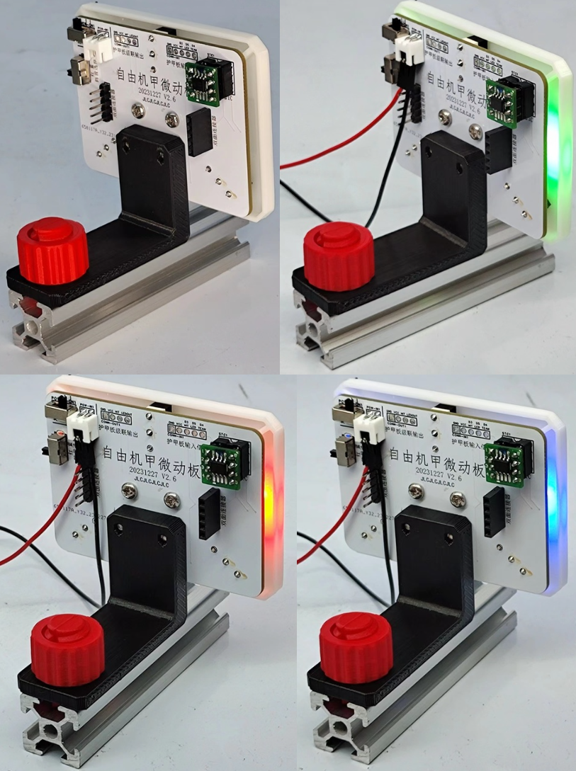
The image below shows the four lighting states of the armored turret.
The circuit design diagrams below are for various versions, including 1.0 and 2.0. Please find the 2024 version 2.9 PCB layout and BOM.
20230708 Bracket Panel 80x60 v2.6.STL
20230422 Armored Turret Fence Support Single Extended v2.1.STL
2020nuts.stl
2020 Right-hand screw with T-type connector.stl
2020 Left-hand screw with T-type connector.stl
PDF_Free Mech Armored Tower Circuit Board.zip
Altium_Free Mech Armored Tower Circuit Board.zip
PADS_Free Mech Armored Tower Circuit Board.zip
BOM_Free Mech Armored Tower Circuit Board.xlsx
91850
DC motor forward and reverse control board based on TC118S low current
Previously, I used microswitches to make forward and reverse switches. This time, I made a small forward and reverse switch based on the TC118S motor driver, intending to use it to make small electric screwdrivers and the like, without using a microcontroller.
The TC118S datasheet specifies a maximum continuous output current of 1.8A and a peak current of 2.5A.
During testing, it operated normally with a geared motor powered by an adjustable power supply at a current limit of 1A.
[Image: Screenshot from Sogou High-Speed Browser 20241002225242.png]

[Image: WeChat image_20240928182417.jpg]

TC118S Single-Channel DC Motor Driver.pdf
October 2 (1).mp4
PDF_DC Motor Forward and Reverse Control Board Based on TC118S Low Current.zip
Altium DC motor forward/reverse control board based on TC118S low current. (zip)
PADS DC Motor Forward/Reverse Control Board Based on TC118S Low Current.zip
BOM_DC Motor Forward/Reverse Control Board Based on TC118S Low Current.xlsx
91852
[Verified] OpenEV2400
The open-source BQ series chip debugging tool offers four versions to choose from.
A quick glance suggests it's the first open-source EV2400 tool available online.
EV2400
Safety Statement:
This project may involve hazardous factors such as high voltage and high temperature. Readers should understand these risks and take appropriate precautions to avoid injury.
Introduction:
The EV2400 is a tool manufactured by Texas Instruments for programming and debugging BQ series devices. The EV2400 is the successor to the EV2300. Compared to the EV2300, the EV2400 has greater compatibility with newer systems and chips.
Counterfeit EV2400s are also available on Taobao and other online marketplaces, but their prices and components are not up to par. Even in 2023, they were still using Type-A connectors, which sparked my idea to create my own EV2400.
Several designs are available in the library:
EV2400 Inexpensive (Figure 3)
EV2400 Affordable [A strange thing on TB uses an F5528 controller; I don't know how the firmware was made] (Figure 4).
Version differences
:
EV2400 Original
, EV2400 Low Cost
, EV2400 Inexpensive,
EV2400 Affordable.
USB isolation
: Yes/No.
I/O protection : Yes /No . TI official update : Yes / No. Unknown MCU: MSP430 , F5529 , F5529, F5529, F5528. Verification status : Yes /No . *In actual use, there is no difference between these different versions. Pin definitions: Official EV2400 pin definitions (Figure 5) OpenEV2400 pin definitions (Figure 6). TI has not publicly released this code in the firmware . However, on CSDN, I found that firmware extracted from the official EV2400 requires UNIFLASH and the ezfet tool for flashing. Unfortunately, if you only make one or two, the cost will be driven up by the ezfet. The MSP430F5529 costs 44 yuan, and auxiliary materials cost 6 yuan, so the cost can be kept under 50 yuan.

EV2400f5529.txt
EV2400f5528.txt
PDF_[Verified] OpenEV2400.zip
Altium_[Verified]OpenEV2400.zip
PADS_[Verified]OpenEV2400.zip
BOM_[Verified]OpenEV2400.xlsx
91853
electronic


 京公网安备 11010802033920号

 JL05-2A22-23PZ-FO-R


