

 (4) Illustrated tutorial:
  remove the LDO chip, disconnect its 3.3V output from the circuit board, ensure proper insulation, and reinstall it. Use six enameled wires to connect the LDO's 3.3V output, the ESC's S-terminal (PWM input), and the four test points. Make sure you remember which wires are connected correctly. Before reinstalling the power cord
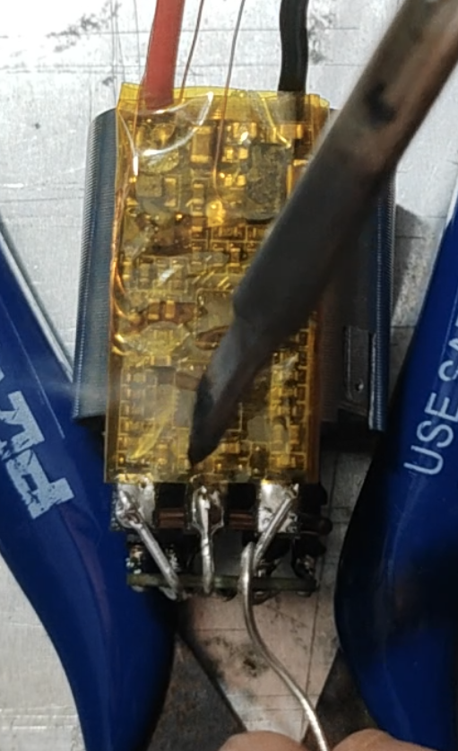
 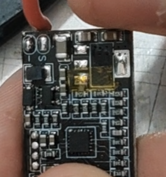 bend the tinned portion of the wire at a 90° angle to shorten the ESC's length.
  The test point definition is shown in the figure.
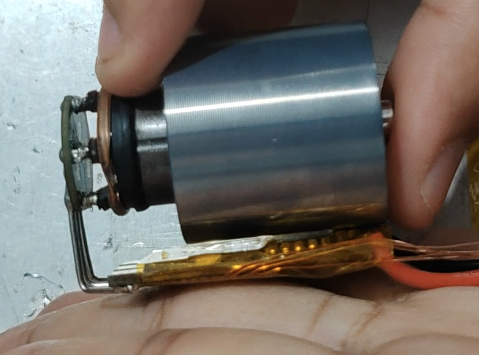
  Wrap the ESC with high-temperature tape and connect it to the motor as shown in the figure. Note that the ESC MOSFET face should face the motor, and the power supply terminal of the ESC should be aligned with the motor's air inlet casing.
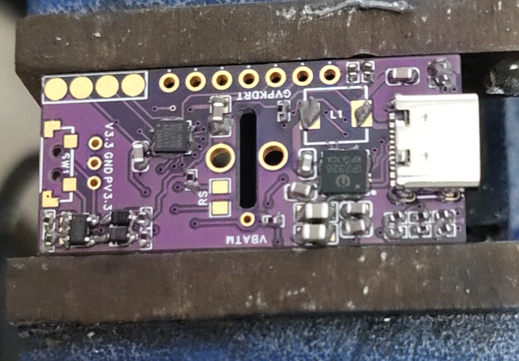
 and mount the components according to the BOM. Note the orientation of the chips and diodes, and ensure that the chips are properly soldered before mounting the inductor. The buttons should be soldered with medium-temperature solder (low-temperature soldering is not strong), and the Type-C connector should also have its housing pins reinforced with medium-temperature solder. [
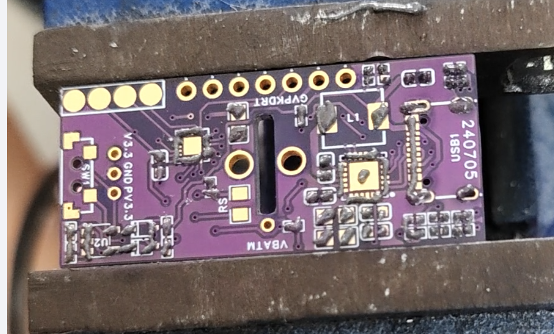
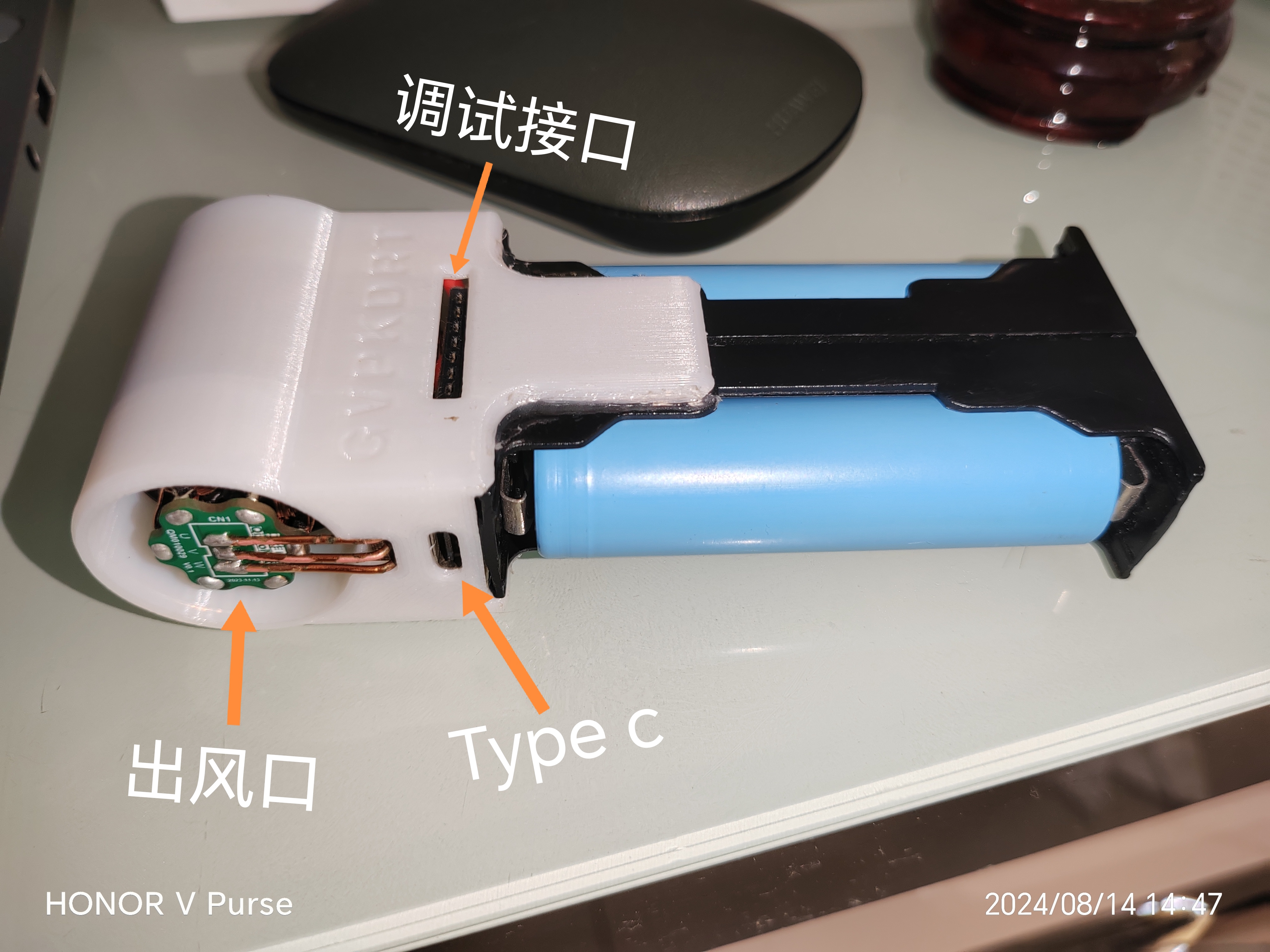
 After checking and confirming everything is in order, use a short-pin connector, bend the pins, and solder it to the debugging interface.
 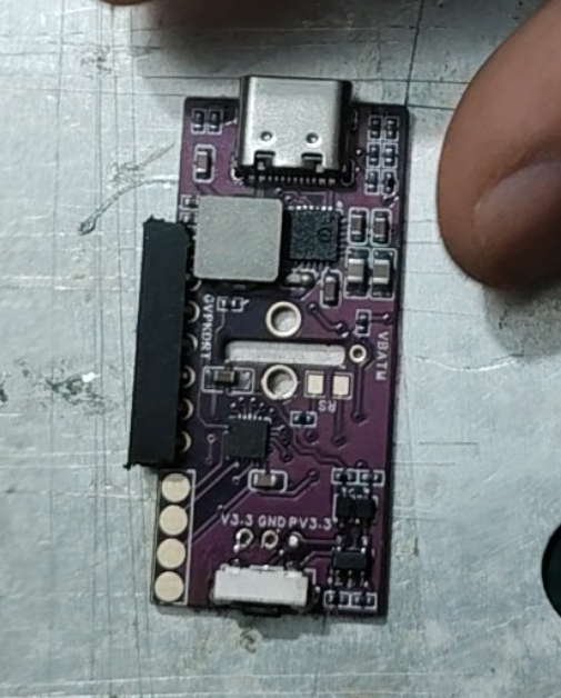 Now you can download the program. Use the STC-ISP software:
  Next, process the sensor. Use two enameled wires to extend the sensor interface
  Then wrap the sensor head with tape twice to slightly increase its thickness (not too thick! Ensure that the sensor is not compressed when the battery compartments are not squeezed, even when the battery compartments are between them!)
 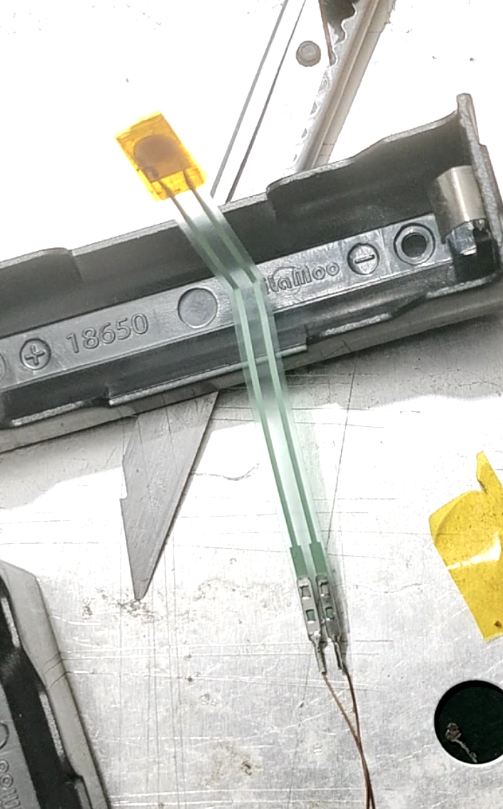 Then bend one of the pins of each of the two battery compartments at a 90° angle to install the motherboard. (Because the two battery boxes are connected in series, one needs to be bent to positive and the other to negative, as shown in the picture:
  Secure the sensor in the center of the battery box with tape. Fold the sensor wire as shown in the picture, with the connector perpendicular to the bottom of the battery box at a 90° angle, so that the connector is located in the gap next to the battery box to prevent interference with the pressure sensor.
 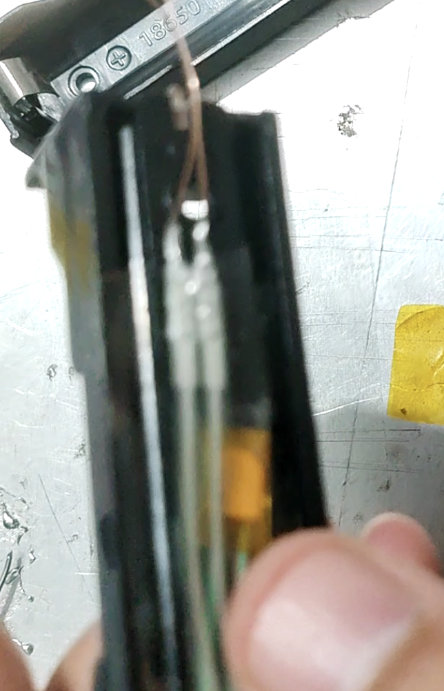 Then solder the two unbent pins of the battery box together, making sure that one is positive and the other is negative. (Ensure a reliable connection!))
 Thread another enameled wire through one of the gaps, solder it to this point, and lead it out as a battery balancing wire.
 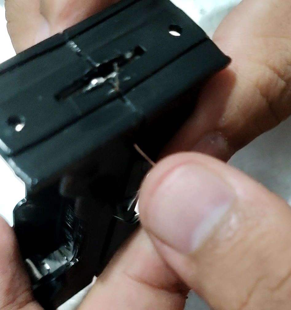 Lead out one balancing wire and two sensor wires from the pin-side, cover the motherboard (note the positive and negative terminals! The Type-C side is positive!), and then solder the three wires to their corresponding pads. As shown in the image:
  Take out the previously processed motor ESC module. Connect the six enameled wires of the ESC to the motherboard as shown in the image:
  The connection is shown in the image:
 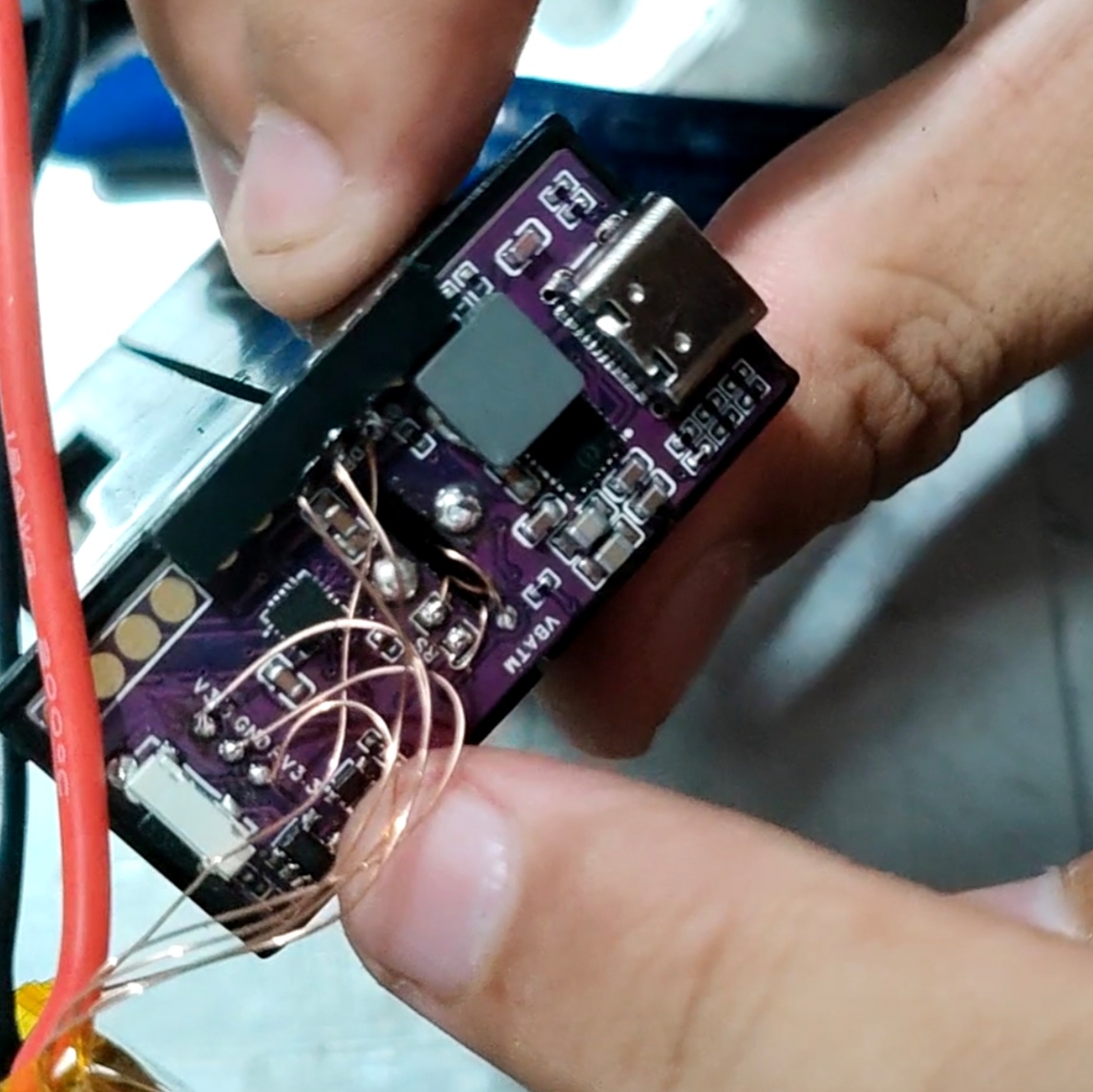 Then, shorten the two power cables of the ESC according to the distance and connect them to the motherboard. (Ensure a reliable connection!)
  Finally, connect the screen. As shown in the picture, the first pin is GND, and the remaining three are soldered in order.
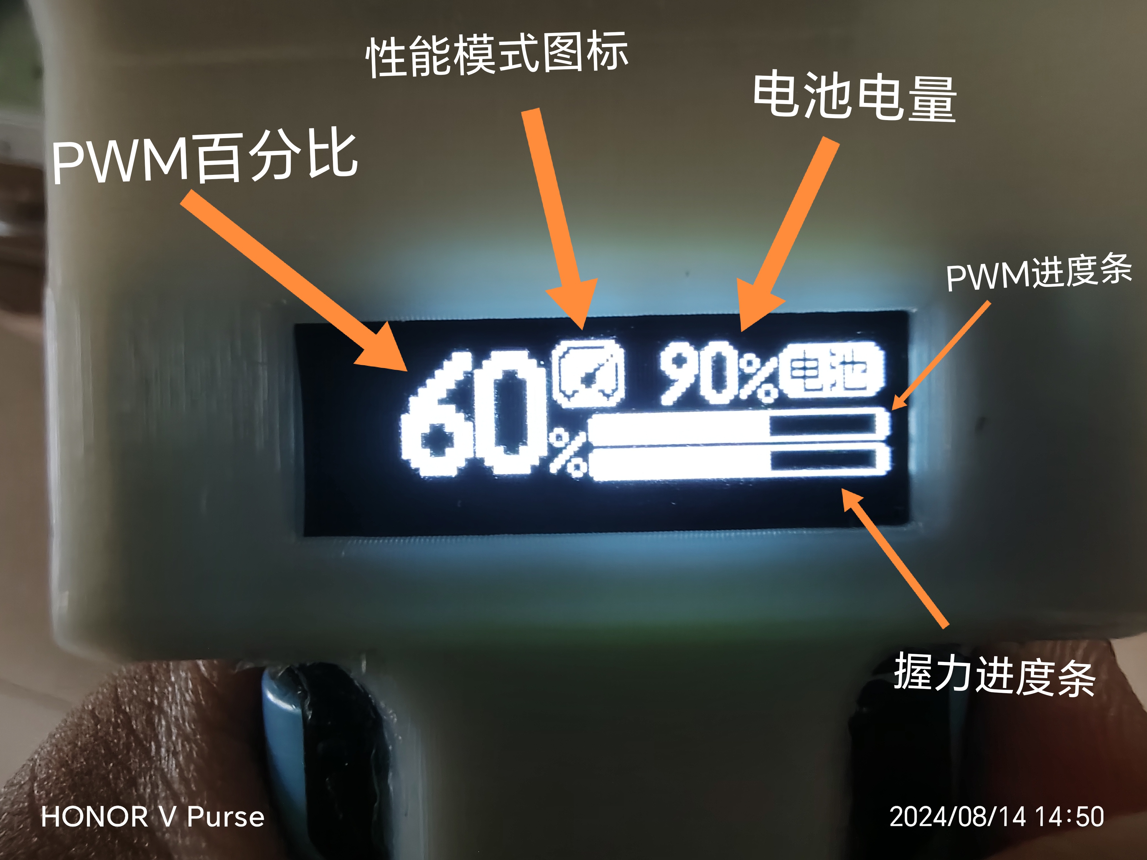
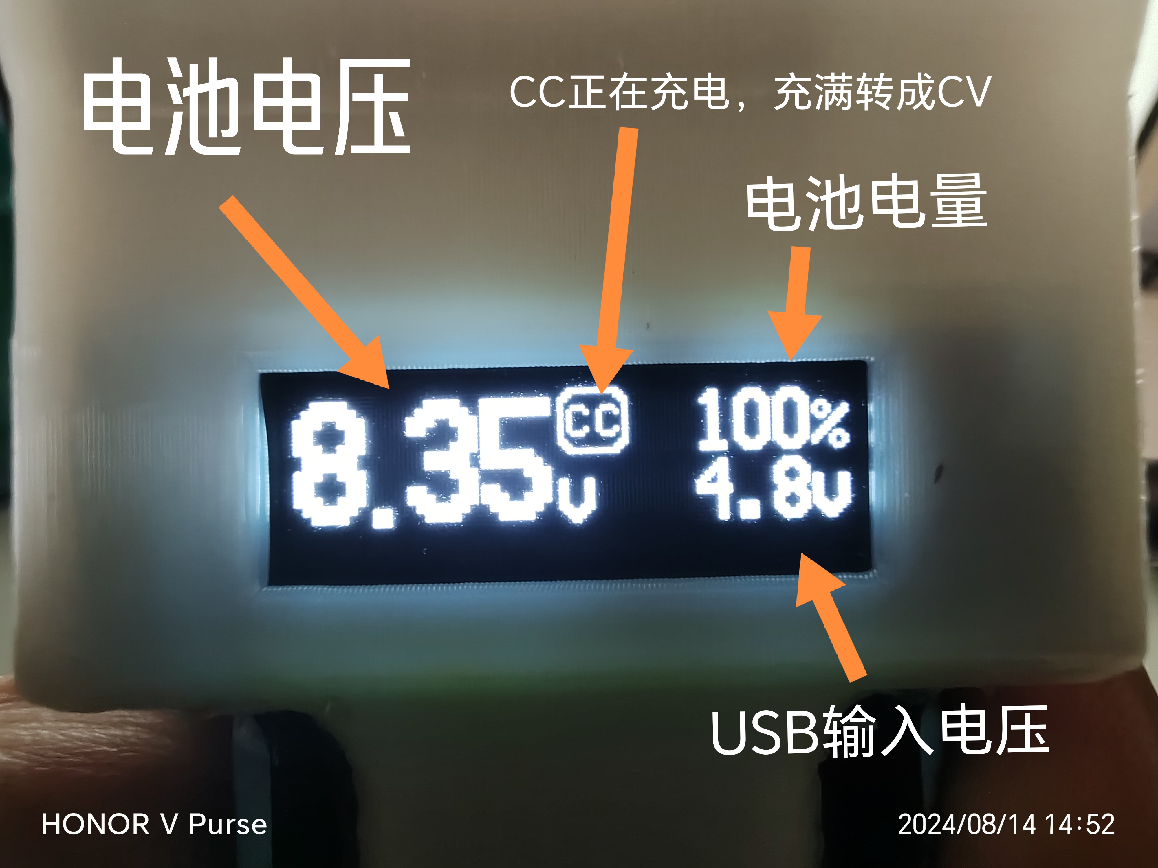
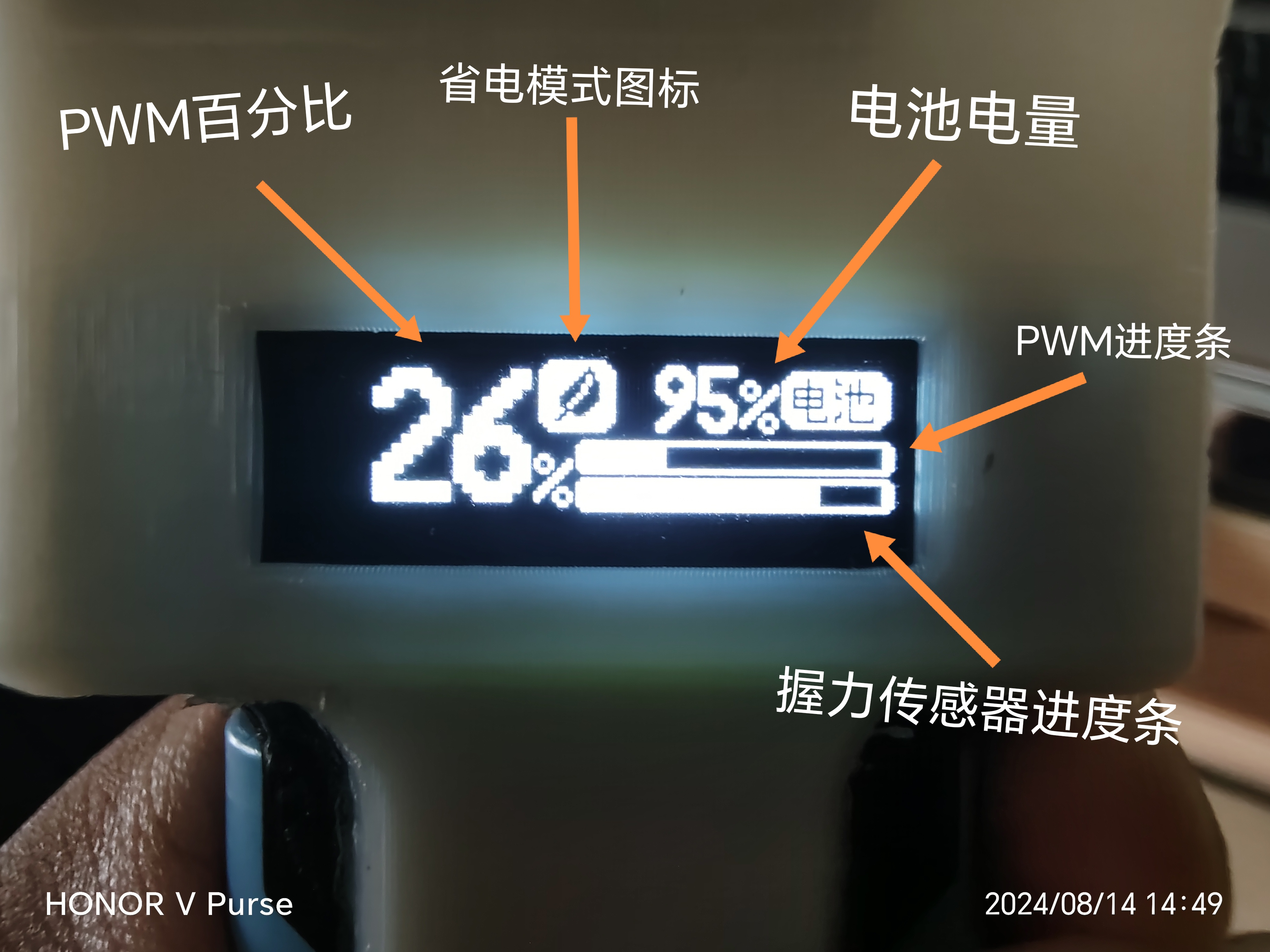
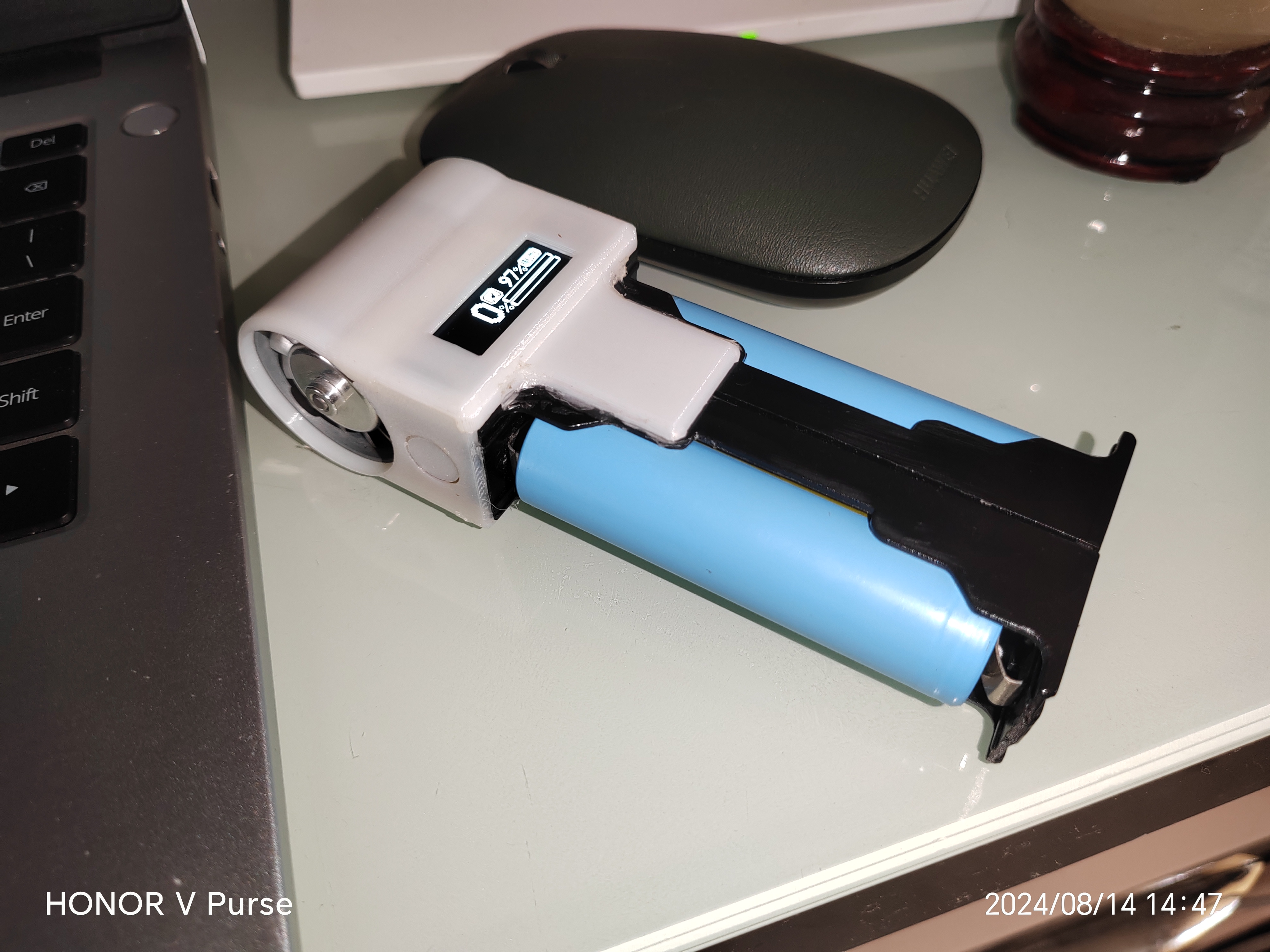
  At this point, the circuit part of this project is complete. Place the screen facing the direction shown in the picture, and then connect the battery (pay attention to the positive and negative terminals! Connecting it backwards will burn it out!). Press and hold the power button for three seconds to turn it on:
 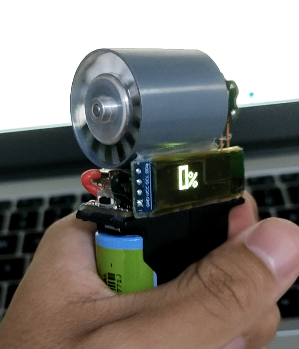 The PWM is not compatible during the first power-on; the speed range needs to be matched.
 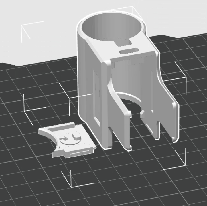 Also, you can wrap the ESC with tape during installation for a neater look!
 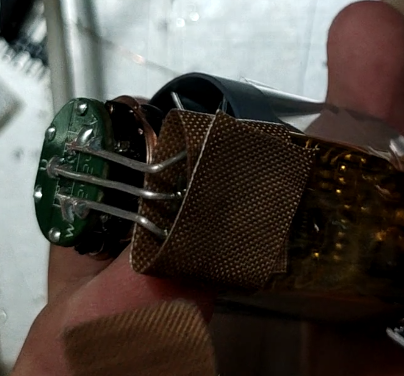 At this point, the process is basically complete. However, the ESC has a default 10-minute inactivity alarm, which will cause the motor to keep making noise during charging. Therefore, the ESC parameters need to be adjusted.
 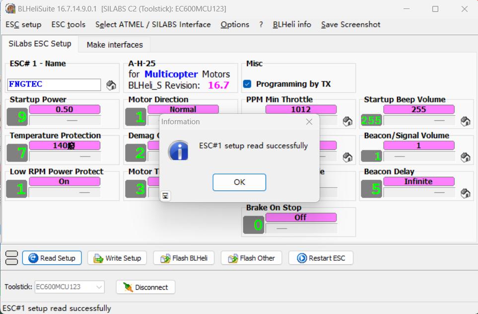 4. Adjust the three parameters circled in red in the image below to the parameters shown in the image. Leave the others unchanged.

All reference designs on this site are sourced from major semiconductor manufacturers or collected online for learning and research. The copyright belongs to the semiconductor manufacturer or the original author. If you believe that the reference design of this site infringes upon your relevant rights and interests, please send us a rights notice. As a neutral platform service provider, we will take measures to delete the relevant content in accordance with relevant laws after receiving the relevant notice from the rights holder. Please send relevant notifications to email: bbs_service@eeworld.com.cn.
It is your responsibility to test the circuit yourself and determine its suitability for you. EEWorld will not be liable for direct, indirect, special, incidental, consequential or punitive damages arising from any cause or anything connected to any reference design used.
Supported by EEWorld Datasheet
EEWorld
subscription
account

EEWorld
service
account

Automotive
development
community

Robot
development
community

About Us Customer Service Contact Information Datasheet Sitemap LatestNews


Room 1530, 15th Floor, Building B,
No.18 Zhongguancun Street,
Haidian District,
Beijing, Postal Code: 100190
China
Telephone: 008610 8235 0740
 京公网安备 11010802033920号

 240-0322-21SPF6K2-18F


