Design Background:
The CW32 digital voltmeter and ammeter is a commonly used electronic measuring tool. Its design background is typically related to the following aspects:
Measurement Accuracy Requirements: Modern electronic equipment demands increasingly higher accuracy in voltage and current measurements. The CW32 digital voltmeter and ammeter achieves high-precision measurements through a high-precision A/D converter and a stable reference voltage source.
Portability and Ease of Use: Traditional analog voltmeters and ammeters are prone to errors during reading, while digital voltmeters and ammeters provide more intuitive and convenient data reading through digital displays. Furthermore, the CW32 is usually designed to be lightweight and portable, facilitating on-site measurements by engineers and technicians.
Multifunctional Integration: The CW32 digital voltmeter and ammeter often features multiple measurement functions, including DC voltage, DC current, AC voltage, and AC current, meeting the needs of different application scenarios. It may also integrate other functions such as data logging, overload protection, and automatic shutdown.
Market Demand Analysis: With the development of electronic technology and the increasing complexity of power systems, the market demand for high-performance measuring instruments is constantly rising. The CW32's design considers the requirements of various applications, aiming to provide suitable solutions.
Technological Advancements: With the development of digital circuit technology and microcontrollers, the CW32 can integrate more functions and reduce costs, thus providing a cost-effective measurement tool.
In summary, the design background of the CW32 digital voltmeter and ammeter combines the development needs of modern measurement technology, the diversified demands of the market, and the possibilities brought about by technological advancements.
Note: Overall Design Scheme Block
Diagram:

Circuit Design and Circuit Principles:
The circuit diagram for this project is drawn modularly. Different modules are divided into sections using lines for easy reading. The circuit diagram will be analyzed module by module below:
1. Power Supply Circuit:
This project uses an LDO as the power supply. Considering that the voltmeter may be used in industrial scenarios with 24V or 36V power supplies, the SE8533K2 with a maximum input voltage of up to 40V was selected as the power supply. The main reason for not using a DC-DC step-down circuit to handle large voltage differences is to reduce PCB area occupation, and a secondary reason is to reduce the cost of the meter.
Considering that high-voltage reverse connection will cause irreversible damage to the module, the voltmeter power supply circuit adopts a series diode scheme for reverse connection protection.

Note: This project uses series diodes for reverse connection protection, taking into account the typical operating scenario where the power supply voltage of this equipment is higher than 5V. The 0.7V voltage drop of the diodes will not affect the power supply. When the power supply voltage is low, due to the overall low power consumption of the project, the measured power supply current is low (20mA). Due to the unique structure of the Schottky diode D4 (1N5819), its VF is lower than that of general switching diodes, and the voltage drop is approximately within 0.2V.
2. Voltage Sampling Circuit:
This project uses a voltage divider circuit to achieve high voltage acquisition. The design can acquire a voltage of 100V, and the current configuration is to acquire a voltage of 0-30V.

The voltage divider resistors in this project are designed to be 220K+10K, therefore the voltage division ratio is 22:1 (ADC_IN11).
3. Current Sampling Circuit:
This project uses a low-side current sampling circuit for current detection. The low-side of the sampling circuit shares a common ground with the development board's meter interface.
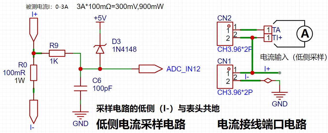
Analysis:
The sampling current designed for this project is 3A, and the selected sampling resistor (R0) is 100mΩ.
The selection of the sampling resistor mainly needs to consider the following aspects:
the maximum value of the pre-designed measurement current; in this project,
the voltage difference caused by the 3A current sensing resistor is generally not recommended to exceed 0.5V;
the power consumption of the current sensing resistor should be selected based on this parameter. Considering the power consumption (temperature) issue under high current, a 1W packaged metal wire-wound resistor was selected.
Voltage amplification factor on the current sensing resistor: No operational amplifier was used to build the amplification circuit in this project, therefore the factor is 1.
Based on the above data, a 100mΩ current sensing resistor was selected. According to the formula, 3A*100mΩ=300mV, 900mW.
4. Digital Tube Driver:
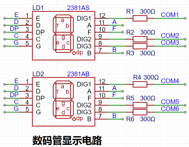
This project uses two 0.28-inch three-digit common-cathode digital tubes for display. They offer better visibility in complex environments. Depending on the actual usage environment, smaller current-limiting resistors can be used to achieve higher brightness. After actual testing, the current-limiting resistors (R1~R6) for the digital tubes were configured to 300Ω.
Digital tubes have better mechanical properties and are not as easily damaged by external forces as display screens. They are widely used in industrial applications requiring stability and reliability. From a development board learning perspective, this makes it easier to learn electronic measurement principles and related development in a targeted manner.
Strictly speaking, the current-limiting resistors should be added to the segments; adding them to the digits would affect the display effect. In our actual design, we added them to the digits to save a few resistors, but the impact on the display is not significant. Therefore, we added them to the digits for convenience.
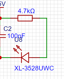
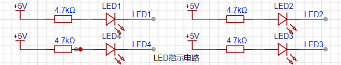
5. Indicator Lights:
This project additionally designed one power indicator light and four IO working indicator lights.
6. Button Circuit Design:
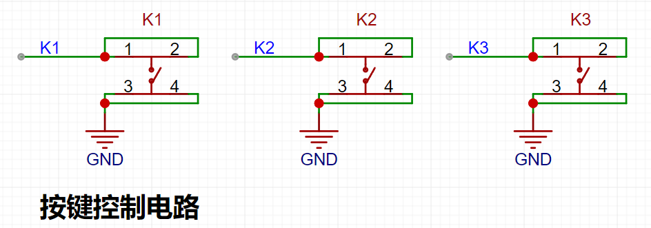
The CW32's I/O ports can be configured with internal pull-up and pull-down resistors, but the external button control circuit does not require configuration. One end of the button is connected to the MCU's I/O, and the other end is grounded. When the button is pressed, the I/O is pulled low.
7. TL431 Circuit Design for Voltage Measurement Calibration:
This project adds an extra TL431 circuit to provide a 2.5V reference voltage. This can be used to provide an external voltage reference for the chip to calibrate the AD converter. From a product design perspective, due to the inherent ADC performance advantages of the CW32, this circuit is not necessary. This circuit is designed on the development board to learn the relevant application principles.

Working Principle:
The core of the 431 is an operational amplifier, which acts as a comparator in the circuit. The chip has an internal Vref voltage (approximately 2.5V), which acts on the inverting input of the comparator. A voltage is input to the non-inverting input of the comparator to REF. When this voltage is greater than Vref, the comparator outputs a high level, enabling the transistor and connecting the CATHODE (cathode) and ANODE (anode) terminals. If REF and CATHODE are at the same potential (connected together), the potential at REF is pulled low. When the potential at REF drops below Vref, the comparator outputs a low level, the transistor turns off, and the potential at REF rises back up. When it rises above Vref, the above process continues, repeating this cycle. Because the hardware response speed is extremely fast, the voltage at REF is almost equal to Vref.
The ADC initialization code is described
below. This code mainly completes the initialization configuration of the current channels ADCH_IN11 and ADCH_IN12. Configured with an internal 1.5V reference, using continuous sampling mode:
void ADC_init(void)
{
ADC_InitTypeDef ADC_InitStructure; //ADC configuration structure
ADC_SerialChTypeDef ADC_SerialChStructure; //ADC sequence channel structure
GPIO_InitTypeDef GPIO_Init_Struct;
__RCC_GPIOB_CLK_ENABLE(); // Enable clock for the corresponding ADC pin __RCC_ADC_CLK_ENABLE(); // Enable ADC clock
PB01_ANALOG_ENABLE(); // Enable analog pin
PB00_ANALOG_ENABLE(); // Enable analog pin
PB10_ANALOG_ENABLE(); // Enable analog pin
PB11_ANALOG_ENABLE();
ADC_StructInit(&ADC_InitStructure); // Initialize ADC default values
ADC_InitStructure.ADC_ClkDiv = ADC_Clk_Div128; // Configure ADC operating clock PCLK/4 = 6/4 = 1.5MHz
/* When the signal voltage is low, the reference voltage can be reduced to improve resolution. After changing the reference voltage, the same binary representation of the voltage value will be different.
The largest binary value (all 1s) represents your reference voltage. When calculating the actual voltage, the reference voltage needs to be taken into account. */ /*
ADC_InitStructure.ADC_VrefSel = ADC_Vref_BGR1p5; // Set the reference voltage to 1.5V
ADC_InitStructure.ADC_SampleTime = ADC_SampTime10Clk; // Since the voltage signal is a slow signal, the ADC sampling time is ten ADC sampling cycles to ensure accuracy
ADC_SerialChStructure.ADC_Sqr0Chmux = ADC_SqrCh11; // Configure the ADC sequence, PB01 is the 9th channel of the ADC
ADC_SerialChStructure.ADC_Sqr1Chmux = ADC_SqrCh12;
ADC_SerialChStructure.ADC_SqrEns = ADC_SqrEns01;
ADC_SerialChStructure.ADC_InitStruct = ADC_InitStructure; // Initialize the ADC
ADC_SerialChContinuousModeCfg(&ADC_SerialChStructure); // ADC sequence continuous conversion mode configuration
ADC_ClearITPendingAll(); // Clear all ADC interrupt status
ADC_Enable(); // Enable ADC
ADC_SoftwareStartConvCmd(ENABLE); // ADC conversion software start command
}
ADC voltage and current calculations are as follows. Where Volt_Buffer is the acquired voltage channel code value, or the calculated voltage value, with voltage in units of 10mV. The current is converted through a 0.1R resistor:
void Volt_Cal(void)
{
float t,KT1;
V_Buffer = Mean_Value_Filter(Volt_Buffer,ADC_SAMPLE_SIZE);//Use mean filtering
I_Buffer = Mean_Value_Filter(Curr_Buffer,ADC_SAMPLE_SIZE); //Use mean filtering
V_Buffer = (V_Buffer * ADC_REF_VALUE >> 12) * (R2 + R1)/R1;
// Rounding
if(V_Buffer % 10 >= 5)
{
V_Buffer = V_Buffer / 10 + 1;
}
else
{
V_Buffer = V_Buffer / 10;
}
ADC_GetSqr1Result(&I_Buffer); ///Display the current acquired value
I_Buffer=I_Buffer * ADC_REF_VALUE >> 12;
/**mv =I_Buffer * ADC_REF_VALUE >> 12,
R = 100mr,
10ma = mv/R/10=mv/0.1/10 = mv
*/
}
Main program:
int main()
{
RCC_Configuration(); //System clock 64M
KEYGPIO_Init();
GPIO_WritePin(CW_GPIOC,GPIO_PIN_13,GPIO_Pin_RESET);
Seg_Init();
Btim1_Init();
ADC_init();
while(1)
{
if(BrushFlag==1)
{
Display(V_Buffer);
DisplayI(I_Buffer);
BrushFlag=0;
}
if(timecount>= 300) //Change the digital tube display value once every 300ms//
{
timecount=0;
Volt_Cal();
BrushFlag=1;
}
}
}
Physical Demonstration Instructions

Calibration Operation Method for this Experiment: This example uses button operation for calibration. The specific operation method is as follows: Define 5 working modes. The K1 key is used to switch the display mode. The K2 key sets the parameter value in the corresponding mode and saves it to FLASH. The K3 key returns to mode 0.
Mode 0: Displays normal voltage and current values (the upper row of digital tubes displays the voltage value *.V or .*V automatically switches, the lower row displays the current value _.**A).
Mode 1: 5V voltage calibration value setting. The upper row of digital tubes displays 5.05. The lower row displays the current voltage value _.V or ._V. In this mode, the multimeter should be set to 5.00V to measure the measured bit. After pressing the K2 key, the current value is calibrated as a 5V voltage value.
Mode 2: 15V voltage calibration value setting. The upper row of digital tubes displays 5.15. The next row displays the current voltage value as _.V or ._V. In this mode, the multimeter should be set to 15.0V to measure the measured value. Pressing the K2 key will calibrate the current value to 15V.
Mode 3: Current 0.5A calibration setting. The upper row of the digital tube displays A.0.5. The next row displays the current current value as _.**A. Pressing the K2 key will calibrate the current value to 0.5A.
Mode 4: Current 1.5A calibration setting. The upper row of the digital tube displays A.1.5. The next row displays the current current value as *.**A. Pressing the K2 key will calibrate the current value to 1.5A.
Project LOGO verification

WeChat_20240816211737.mp4
WeChat_20240816211727.mp4
CW32 voltage and current meter.zip
Digital voltmeter and ammeter.rar
PDF_Voltage and Current Meters.zip
Altium_voltmeter_currentmeter.zip
PADS_Voltage and Current Meter.zip
BOM_Voltage and Current Meter.xlsx
93058
electronic


 京公网安备 11010802033920号

 MS765-D


