I. Design Summary
A color measurement system based on the TCS34725 color recognition sensor.
The TCS34725 communicates with the Air32F103 microcontroller via an I2C interface, reading the color data from the TCS34725 and sending configuration commands to adjust the sensor's operating parameters.
The display screen uses an SPI interface to transmit data with the Air32F103, sending color data and commands to the display screen for real-time data display.
The UI design utilizes LVGL;
FreeRTOS is ported to ensure real-time performance;
communication with the PC is achieved using a USB virtual serial port based on the MODBUS communication protocol.
II. Overall Design Block Diagram
The following is the system block diagram of the color measurement system:

Figure 2 Color Measurement System Block Diagram
The entire system block diagram shows the communication between the Air32F103 microcontroller and the TCS34725 color sensor via the I2C interface, and integrates a 1.69-inch color TFT display screen, a USB virtual serial port, an SWD download circuit, and power supply and LDO circuits.
1) TCS34725 Color Sensor: Senses ambient colors and transmits raw data to the Air32F103 microcontroller via I2C interface.
2) 1.69-inch Color TFT Display: Receives color data from the Air32F103 microcontroller via SPI interface and displays it on the screen. Provides a user-friendly interface and real-time display of color measurement results.
3) Air32F103 Microcontroller: Receives color data from the TCS34725 sensor via I2C interface, performs data processing and analysis. Simultaneously, it communicates with the TFT display via SPI interface, sending processed data to the TFT display for real-time display.
4) USB Virtual Serial Port: Connects to a computer via USB interface, providing users with an interface to communicate with the system. This allows monitoring of system operation via computer and sending and receiving necessary serial communication data.
5) SWD Download Circuit: Provides an SWD interface for firmware download and debugging. During development, the firmware on the Air32F103 microcontroller can be easily updated and debugged via the SWD interface.
6) Power Supply and Low Dropout Regulator (LDO) Circuit: Used to provide stable power to the TCS34725 color sensor, Air32F103 microcontroller, and screen to ensure their normal operation.
III. Hardware Circuit Composition
Based on the above system block diagram, the hardware circuit design is as follows:
For the Type-C surrounding circuit, pins CC1 and CC2 are grounded via a 5.1KΩ resistor. After connecting to the PC via the data line, the device is selected as a SLAVE (slave) device. A reverse polarity protection diode is placed between the USB input positive voltage and the onboard positive voltage to ensure circuit safety. DP and DN differential data lines are led out as USB virtual serial communication lines. An LED and a current-limiting resistor are connected between VBUS and a pin of the microcontroller for convenient system operation, debugging, and visualization.

Figure 2 shows the circuit design surrounding Type-C.
For the basic communication circuit, an SWD download circuit debugging interface is brought out. The DP and DN differential data lines of Type-C are connected to the PA11 and PA12 pins of the microcontroller through a 22Ω resistor, and the DP data line is pulled up through a 1.5KΩ resistor to realize the hardware circuit application of USB virtual serial communication.

Figure 3 shows the basic communication circuit design
. For the power supply and low dropout regulator (LDO) circuit, the commonly used 3.3V low dropout linear regulator AMS1117-3.3 chip is selected as the 5V to 3.3V power supply and low dropout regulator. This chip is inexpensive and has stable performance, with overvoltage protection, which helps to prevent damage to the system from sudden increases in external voltage. Three sets of 10uF and 100nF capacitors are placed between the 3.3V forward voltage and GND. These are planned for the forward voltage input pins of the onboard microcontroller chip, color recognition sensor, and TFT display driver. This reduces voltage ripple generated during wiring, lowers power supply noise, stabilizes the power supply voltage, minimizes interference to the chip, and provides a reliable operating environment for each component. This is crucial for accurate measurement by the color sensor and stable operation of the microcontroller.

Figure 4 shows the power supply and low dropout regulator (LDO) circuit.
For the microcontroller chip's peripheral circuitry, considering the operating frequency requirements of LVGL and FreeRTOS, the microcontroller's internal 8MHz high-speed clock cannot meet the minimum operating requirements. Therefore, an external crystal oscillator is connected to the clock input pin of the Air32F103 microcontroller to provide a stable clock source. The Air32F103's clock source is divided by a PLL to obtain different system clock frequencies. All external pins of the Air32F103 microcontroller are brought out for connection to various peripherals, such as GPIO, USART, SPI, and I2C, configured according to application requirements.

Figure 5 shows the peripheral circuitry
for the TCS34725 color sensor. A 3.3V supply provides the operating voltage for the TCS34725 sensor. The sensor uses an I2C interface for data communication, with SCL (clock line) and SDA (data line) connected to the corresponding microcontroller pins. The microcontroller's LED_CONTROL pin is connected to a white LED via an NPN transistor, controlling the LED to provide illumination in poor lighting conditions, facilitating normal color signal acquisition by the TCS34725 color sensor.
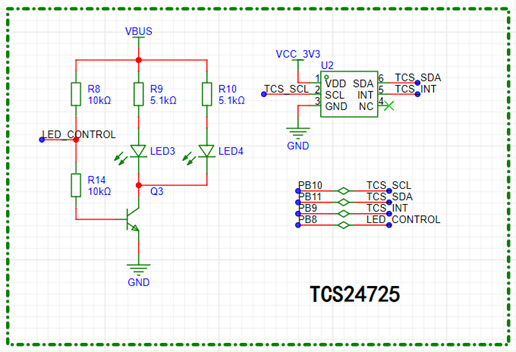
Figure 6 shows the peripheral circuitry for the TCS34725 color sensor .
For the 1.69-inch color TFT display screen, the peripheral circuitry mainly involves power supply, display control, and data communication. To ensure a stable operating voltage for the 1.69-inch TFT display screen, a 3.3V power supply pin is connected according to the display screen's specifications; the microcontroller's SPI pins (MOSI, SCK) are connected to the corresponding SPI pins of the TFT display screen. The SPI clock frequency is set correctly and is compatible with the display specifications. Connect the microcontroller's GPIO pins to the corresponding control pins (Chip Select, Data/Command, Reset) of the TFT display. These pins are used to control data transmission, chip selection, reset, and other operations. Connect the microcontroller's GPIO pins to the TFT display's backlight control pins to adjust the backlight brightness.

Figure 7 shows the peripheral circuit of the 1.69-inch color TFT display.
IV. Program Flowchart
The color measurement system based on the TCS34725 color recognition sensor involves the software architecture of TCS34725 color acquisition, implementation of automatic gain control based on a sliding window AGAIN, LVGL display, USB virtual serial port implementation for communication with the PC based on the MODBUS protocol, MODBUS protocol virtual register implementation, and FreeRTOS system porting. The software code architecture is described in two parts below.

Figure 8 shows the software initialization of the color measurement system.
First, the system performs a power-on reset and RCC clock tree frequency division initialization to provide suitable operating frequencies for various peripherals and the system. Next, it initializes the GPIO parameters of the peripherals, including input/output modes, output speed limits, and whether pull-up/pull-down switches are enabled. Then, it initializes the USB virtual serial port and MODBUS communication virtual registers, allowing the PC to access the microcontroller's color and gain virtual registers generated by the color measurement system via the USB virtual serial port and MODBUS protocol, and read the values. Finally, it initializes the FreeRTOS tasks, which are divided into four threads.
The first thread is related to LVGL display refresh callbacks; the second thread is related to USB virtual serial port and MODBUS communication; the third thread is related to display data refresh; and the fourth thread is related to TCS34725 color acquisition.

Figure 9 shows the color measurement system's running code architecture .
After the color measurement system completes its functional initialization, it runs the FreeRTOS system, executing tasks in a multi-threaded manner. The first thread handles LVGL display refresh callback tasks, periodically calling the `lv_tick_inc(LVGL_TICK)` function to obtain the LVGL running clock. The second thread handles USB virtual serial port and MODBUS communication tasks, periodically calling the `RS485_Service()` function to process serial data, identify the MODBUS communication protocol, and respond to the PC. The third thread handles display data refresh tasks, calling the `lv_table_set_cell_value_fmt()`, `lv_led_set_color()`, and `lv_bar_set_value()` functions to update the display data. The fourth thread handles TCS34725 color acquisition tasks, periodically calling the `adjust_gain(rgb, &brightness_window)` and `TCS34725_GetRawData(&rgb)` functions to determine AGAIN automatic gain control and acquire and process color data.
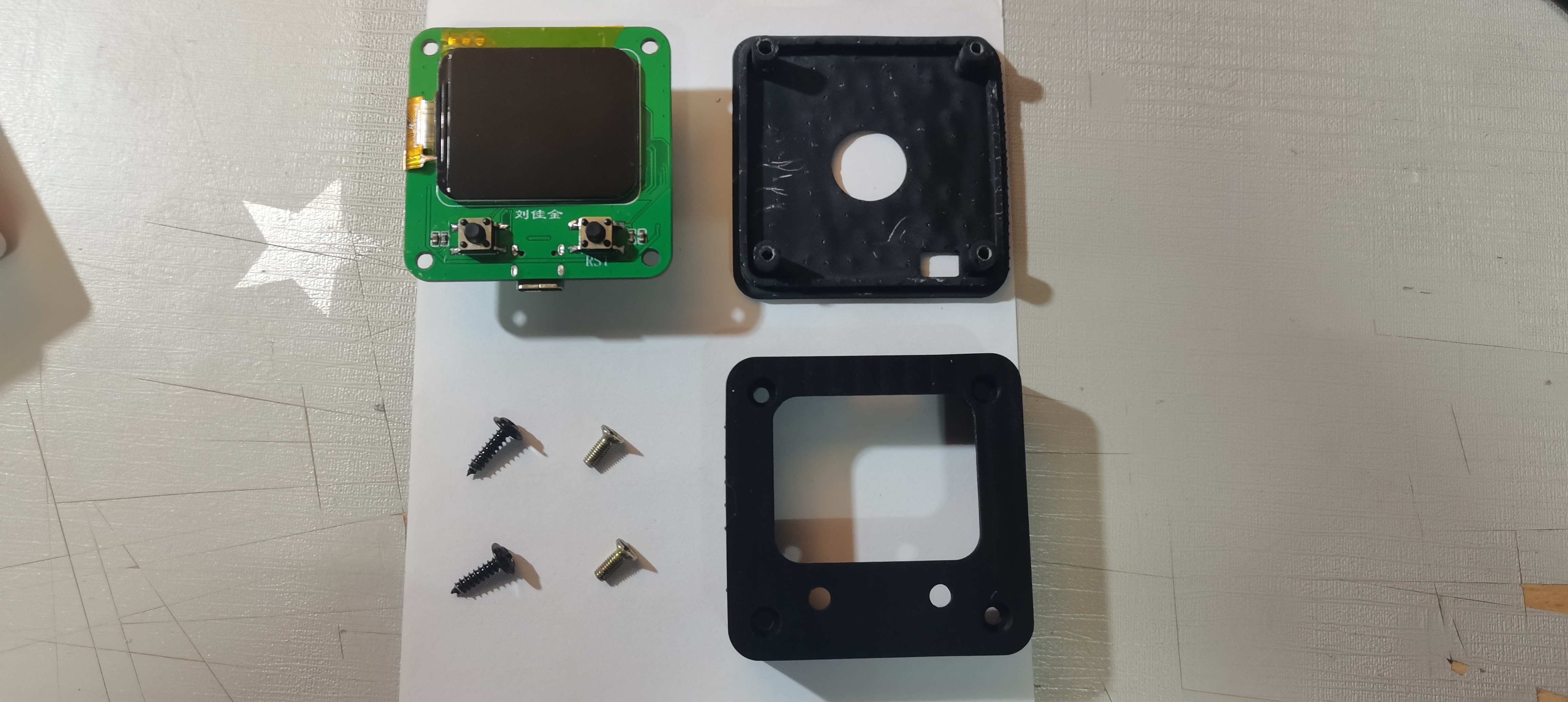
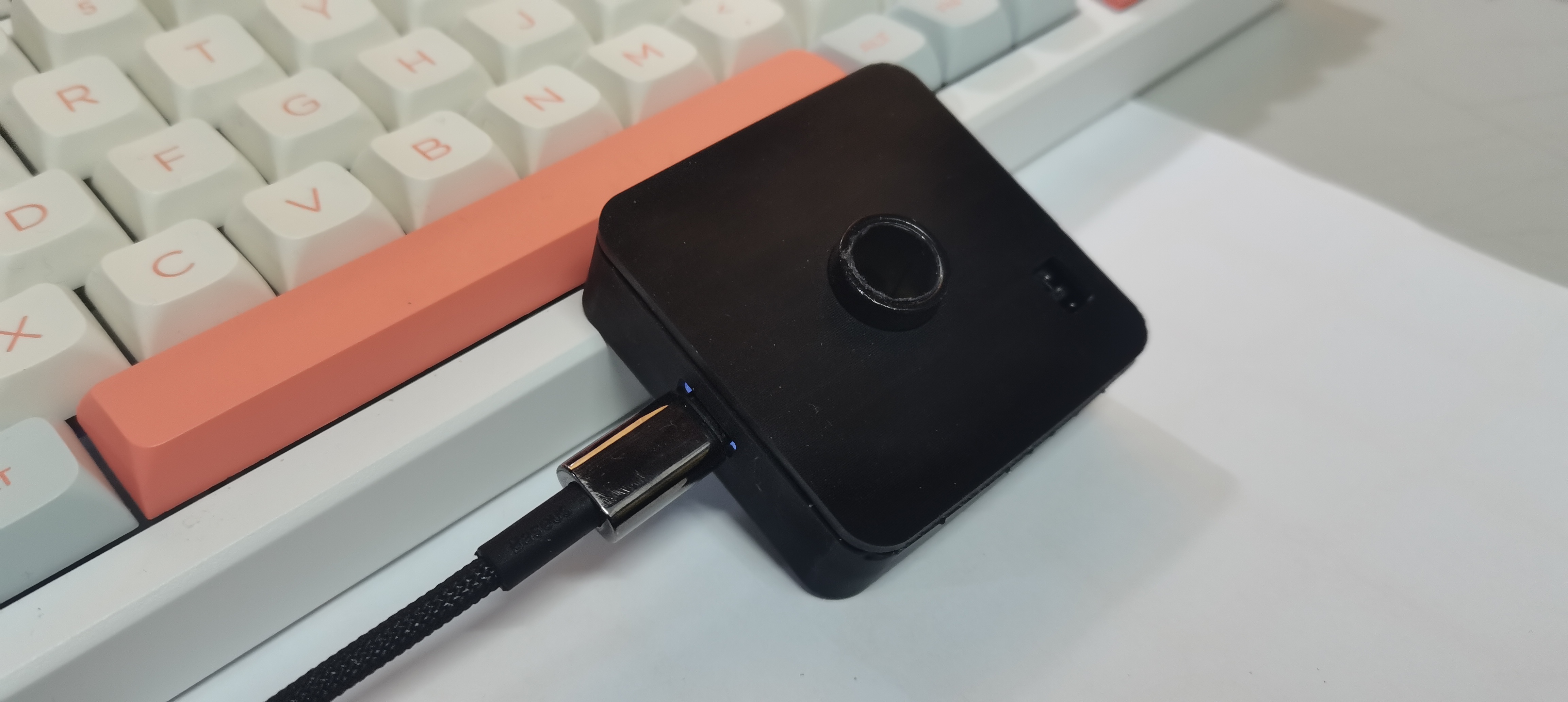
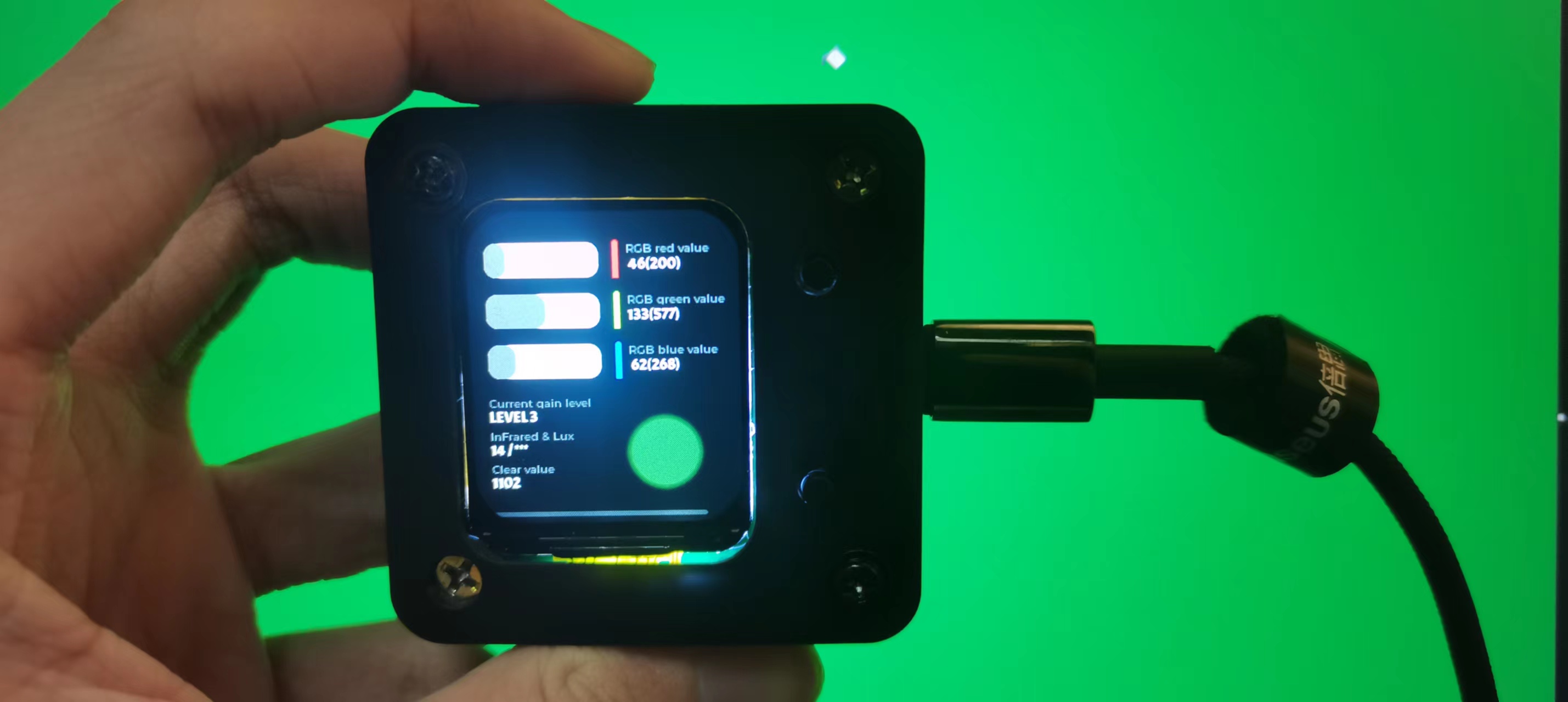
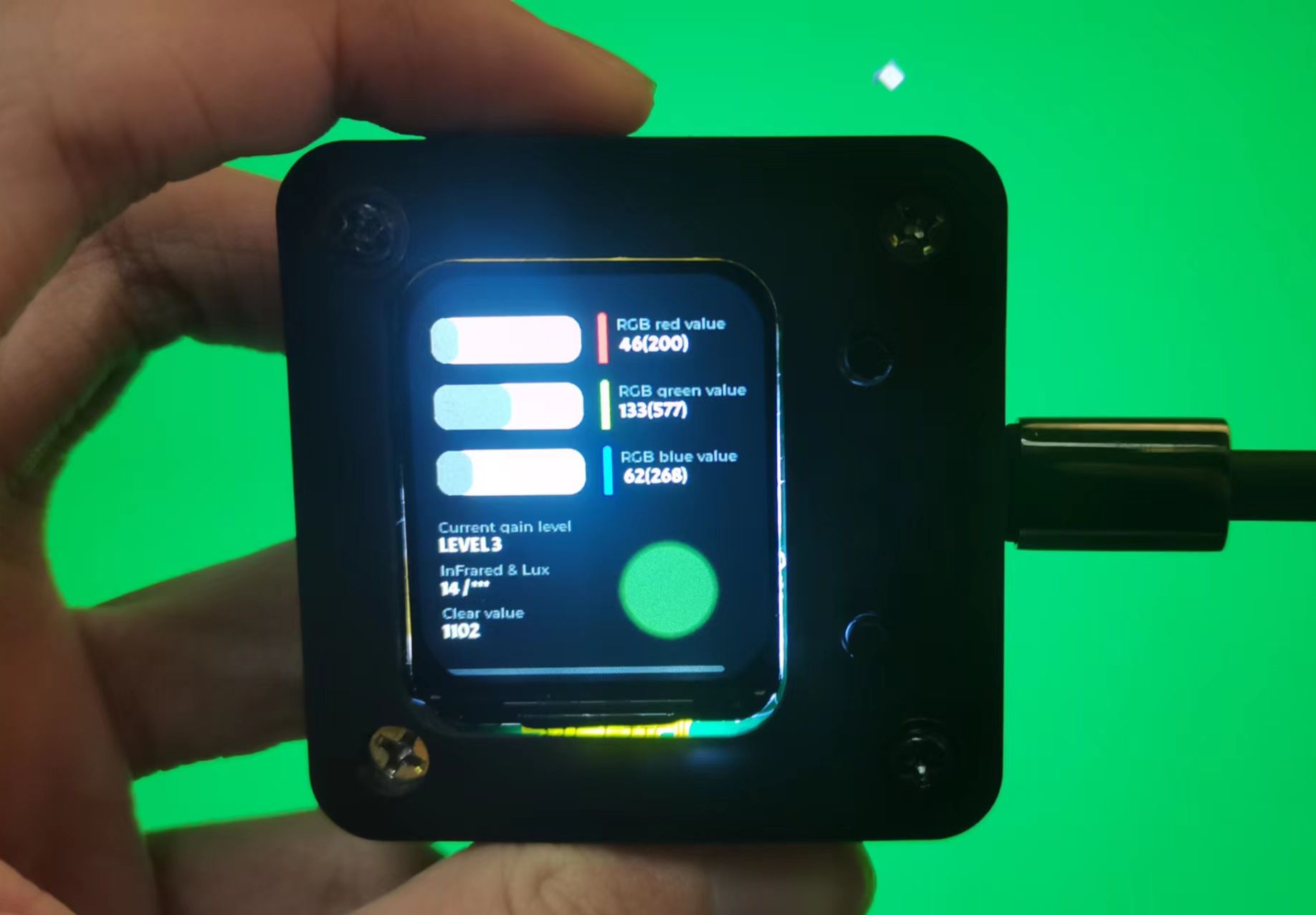
V. Physical Demonstration


VI. Notes
The source code I provided may differ slightly from the code architecture section in this article. The code architecture in this article is the best I could come up with after completing this small project and writing all the code. I haven't had time to modify the source code yet.
VII. Demo
Video I don't know how to upload a demo video, so I'll just post a few pictures here (I spent a long time tweaking the code).


PCB.zip
Shell.zip
src.7z
de00d672e8ec6476736b2085eda28986.mp4
PDF_RGB Color Recognition Based on TCS34725.zip
Altium_RGB Color Recognition Based on TCS34725.zip
PADS_RGB Color Recognition Based on TCS34725.zip
BOM_RGB Color Recognition Based on TCS34725.xlsx
90953
LED Encoder
The LED encoder
includes LED rings, schematics and PCB layouts of the upper and lower boards,
and the program's HEX file.
Project Description:
This LED encoder controls the display of an LED ring by rotating the encoder. It also provides multiple control output methods.
Open Source License
: TAPR Open Hardware License (Unauthorized reproduction prohibited).
Project Functionality:
Controls the display of an LED ring by rotating the encoder. It also provides multiple control output methods.
Project Attributes:
This is the first public release of this project and is my original work. This project has not won any awards in other competitions.
Project Progress
: Completed .
Instructions for Use:
1. Power Supply:
Connect PIN3 and PIN4 of the H2 interface to the positive power supply. The power input is 3.3-5V.
Connect PIN1 and PIN2 of the H2 interface to the negative power supply.
After power is supplied, the LED ring will light up and turn off according to the voltage of the potentiometer.
2. Mode Adjustment
: Press and hold the encoder for 3 seconds to switch modes.
After switching modes, an LED display will appear. Several consecutive lit LEDs indicate the mode.
The mode switching order is:
Mode 1 -> Mode 2 -> Mode 3 -> Mode 4 -> Mode 5 -> Mode 6 -> Mode 7 -> Mode 8 ->
Mode 1. Mode 1: Mode
1 LED display:
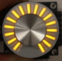
Mode 1 is pointer mode.
Mode 2:
Mode 2 LED display:

Mode 2 is pointer inverted color mode.
Mode 3:
Mode 3 LED display:
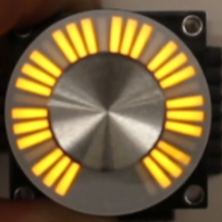
Mode 3 is a fan-shaped inverted color mode.
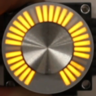
Mode 4: Mode
4 LED display : Mode 4

is a fan-shaped mode.
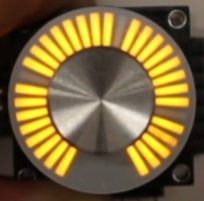
Mode 5:
Mode 5 LED display:

Mode 5 is a super fine-tuning mode. Mode
6: Mode
6 LED display: Mode
6 is a super meteor trail mode.
Mode 7:
Mode 7 LED display:

Mode 7 is the vehicle CAN communication mode.
Mode 8:
Mode 8 LED display:
Mode 8 is the analog encoder mode. 3. Install the upper and lower panels as shown in the diagram below. Design Considerations: 1. 3.3V power supply is recommended . 2. Minimize the number of times the upper and lower boards are plugged in and out. 3. Electrolytic capacitors need to be soldered in cases of high power supply noise. Other [LED Encoder 6 Modes Super Fine-tuning Super Meteor Trail - Bilibili] https://b23.tv/rtXNGqM [LED Encoder CAN Communication Mode Display Power-Off Protection - Bilibili] https://b23.tv/2WUQDH5 [LED Encoder Light Ring Making/Principle/Quick Start Tutorial - Bilibili] https://b23.tv/hMvm4IG


LED Encoder V1.hex
LED Encoder - Quick Start Guide.pdf
PDF_LED-encoder.zip
Altium_LED-encoder.zip
PADS_LED-encoder.zip
BOM_LED-encoder.xlsx
90954
ESP32-S3 Multifunctional Independent Secondary Screen [iCRT]
A retro-style multi-functional secondary screen created using an ESP32S3, taking two months to develop:
AIDA64 secondary screen,
music spectrum metronome,
dynamic weather clock, and
video playback.
Demonstration Video
: [Open Source] Retro Multifunctional Secondary Screen "iCRT" - Music Spectrum Beats, Animated Weather Clock, Check it out! _Bilibili_
2024-1-22 Update:
Dock completed.
Dock for the multifunctional secondary screen "iCRT" - JLCPCB EDA Open Source Hardware Platform (oshwhub.com).
All components are available for download here: https://pan.baidu.com/s/19-CHRh_MAejMqFVaL9os6Q?pwd=e8y5. Join
our production discussion group: 739444215.
I previously posted some boards on SMT; if interested, you can buy them directly from my workshop:
https://gf.bilibili.com/item/detail/1105534080 . The creation
of
this iCRT originated from my previous game console project, "Old Tyrant Game Console." Shortly after completing the game console project, I accidentally saw an old photo of a CRT monitor I used to use, which brought back many memories. Since I wasn't quite proficient with the Fusion360 yet, I thought I'd take this opportunity to practice curved surface design. That's how I started this project. When I first got my hands on the 3D-printed casing, my friend and I thought it looked great, and many people liked it too. So, I had the idea to give it a soul—a PCB and software—making it an independent tool, not just a display device. So, I designed the board, made the board, soldered it, wrote the code, modified it, added features, and finally, it became the "multi-functional secondary screen device that exhausts my current technical capabilities."
PS: The name iCRT comes from my son; I actually named it MiniCRT before.
Features:
Currently, iCRT includes the following features:
AIDA64 secondary screen, implemented through RemotePanel, with percentage and progress bar animation effects;
music spectrum and metronome, which collects ambient sound through an internal microphone, performs FFT processing, and real-time beat detection to display beautiful spectrum effects and RGB light effects;
dynamic weather clock, which obtains weather information through the Gaode Map API and reads the corresponding dynamic effects as the background.
Video playback features pre-processed Mjpeg+MP3 files with synchronized audio and video
display, and JPEG files are shown.
AIDA64
provides a brief overview of several current secondary screen implementation methods and why iCRT is called an "independent" secondary screen. The secondary screen is primarily used to display current computer information, such as CPU and GPU temperature, usage, and frequency, and may incorporate some personalized elements; in short, it's like a dashboard. The main methods to achieve this are:
Extended Display: Connect the display device to the computer's display interface, then use it as an extended monitor to extend the computer screen to that monitor, and move the AIDA64 dashboard to the extended screen. Advantages: good effect, large screen, and strong performance; Disadvantages (in my opinion): Extended display consumes some graphics card performance, and it's easy to accidentally move the mouse to the extended screen, sometimes making it difficult to know where the mouse went, which is annoying when playing large games in full screen.
Independent Web Display: Use a separate peripheral device, usually an Android phone, Raspberry Pi, or other device that can access and display web pages, to remotely access the web page provided by AIDA64 for display. Advantages: It does not affect computer performance, is independent of the computer, and can be placed elsewhere. Disadvantages: The RemotePanel web page display provided by AIDA64 has limited effects and cannot display custom gauges and animation effects.
Independent Custom Display: Through... This project involves a standalone peripheral remotely accessing data provided by AIDA64 (or data from a custom-written host computer) and displaying it according to a customized style. The advantage is that it doesn't affect computer performance, is independent of the computer, and can be placed elsewhere. The disadvantage for this project is the performance limitation of the ESP32-S3, which prevents displaying better, clearer effects and animations. Ideally, it would be a powerful Android secondary screen with a UI designer and an Android app. Third
-party peripherals: AIDA64 supports some third-party peripherals, such as Logitech and Razer products, which use custom protocols for data transmission. The advantages are a unique design and compatibility with devices (I haven't used them). The disadvantages are also (I haven't used them).
This project obtains information from AIDA64's RemotePanel, parses it, and displays it through a custom UI. Unique meter animations have been added to CPU and GPU usage, including a line graph effect that changes over time. Animations have also been added to hard drive and memory usage.
Additionally, the image in the lower left corner can be changed to personalize the display.
The music spectrum and metronome are easily changed directly on the webpage, without needing a card reader.
I
've always loved the music visualization and spectrum features. Previously, I used a computer to capture audio, performed an FFT, and sent the data to an ESP32 for display. This time, I captured ambient sound in real-time and analyzed the data. I tried several microphones—analog and digital—and tested several digital ones. Currently, the ICS43434 is the best performing, but also the most expensive. I tried several real-time beat detection algorithms and spent a lot of time on this one; it's the best real-time beat detection I could achieve. It judges beats by the change in sound energy within a window period and can adapt to most songs. After detecting a beat, the RGB light flashes once. This can be extended via the base. The interface connects to external speakers and RGB light strips, which can also blink synchronously. A dynamic gain algorithm has been added to the microphone acquisition, which dynamically increases or decreases the scaling ratio by judging the average sound intensity over a recent period of time, so as to achieve perfect spectrum display and beat detection at any volume.
Dynamic weather clock
. A long time ago, there was a mobile phone manufacturer called HTC. When I saw the dynamic background that changed with the weather on other people's phones, I was amazed. I thought it was so cool. When I made the weather clock, I thought that I must have a dynamic background. The weather animation in this project comes from the HTC SENSE weather animation found online. HTC's mobile phone business has been discontinued for many years. If HTC informs me that it cannot be used, please let me know and I will delete it immediately. The weather updates every 3-5 minutes, currently using my Gaode API. If you have your own API, you can apply for it and fill in your usage. When the weather changes, there will be a smooth switching animation. The clock includes the display of Gregorian and Lunar calendars, common holidays, and the 24 solar terms.
Video playback
may not be called video playback. The ESP32-S3 is just a microcontroller for IoT and does not have video encoding and decoding functions. Even JPEG decoding is just software decoding. The video playback in this project is done by processing the video into an MJPEG file + MP3 file, saving them with the same main file name, and then copying them to the playback directory. The device will decode and play them synchronously. MJPEG must be 25 frames per second because it is based on 25 frames per second for audio and video synchronization. MJPEG decoding uses the latest and fastest SIMD decoding, which is the fastest decoding that the ESP32-S3 can do, 50-80% faster than ordinary decoding libraries such as JPEGDEC.
Image playback
is the same as above, nothing much to say, it just plays images
. The above are all the functions currently implemented by iCRT. Its positioning is as an all-around secondary screen and desktop decoration. All the above functions are based on this need. Its hardware can also port the code of the old T-Rex game console to play FC games. If needed, it will be added in
future updates
(i.e., leaving room for future updates).
Multi-city weather switching (for your and your partner's convenience),
WeChat mini-program control (although both web and button controls are available, wouldn't mobile control feel more stylish?),
more AIDA64 UI interfaces (I'm not a design professional, so I might need some design solutions from professionals),
separate MP3 playback? (This speaker is so crappy, no one would want to use it to listen to music, right?).
The expansion dock is under development. Expansion ports have already been reserved. The expansion dock is planned to have larger speakers, more RGB ambient lighting, and a USB 2.0 docking station. This will add the functionality of an
old-school game console. With the expansion dock, it can be powered, and the existing USB port on the back can be used to connect a controller to run game console programs.
Control methods
are via buttons on the back of the device: long press to bring up and confirm the menu, short press to go to the next function or the next item in the menu. Control via Web: After successful device network configuration, the device's IP address can be seen at the top of the AIDA64 interface. Entering this IP address in a browser will display the device's control page, making control more convenient and flexible.
When
there is no Wi-Fi information, the device will automatically activate the network configuration access point (AP). The SSID is Crt-Ap, and the password is 12345678. After connecting, the network configuration page will automatically pop up after a short wait and will automatically search for Wi-Fi hotspots in the current environment. Select your network, enter the password, and the network configuration will be complete after a short wait. If the network changes and reconfigure is required, you need to select "Clear Wi-Fi Information" in the settings interface to clear it. This will allow the network hotspot to be reactivated upon the next startup.
Activating
this project took a lot of time, effort, and a small amount of money. Since CRT shell printing is expensive, I also spent a day creating a cheap, open-source youth version shell for DIYers to use. I don't want to, and can't, make money from this, but I hope my time has some value and that I can gain recognition and appreciation. A 9.9 yuan activation code (enough for a discounted cup of Luckin Coffee) allows you to use the firmware I've been developing for a year, as well as future updates based on my interests. If you're too lazy to develop it yourself, you can buy my pre-assembled SMT product.
I have a small dream: that my creations and code will be appreciated by others, and that it will help me achieve my goal of making Luckin Coffee freely.
Hardware configuration
: Microcontroller: ESP32-S3-N8R8;
Display: 3.2-inch 320×240 IPS SPI display (expensive);
Storage: TF card, SDMMC 4-bit mode;
Audio playback: MAX98357 + ordinary small speaker;
Audio acquisition: ICS43434. Additional equipment: Digital I2S microphone;
WS2812 LED control;
USB: USB interface supports reversible insertion; reversible insertion is the CH340X serial port for burning devices; reverse insertion is the ESP32-S3's built-in USB, which can be used as a host to connect game controllers within the game console firmware
; Shell: 3D resin printed retro CRT monitor design (nostalgic version, expensive) and stylish calendar design (youth version, cheap); Two
programming platforms
: IDE: platformio + arduino, 6.4.0, graphics framework is lvgl
open source.
After much consideration, I decided to open source the PCB and youth version shell, so that friends who want to make their own can do so. Firstly, because I can't forget my original intention in making things, which is to share the interesting and fun things I make; secondly, because I promised many group members that I would open source the content other than the code. Due to the more than a year of effort spent on the project, and the fact that it contains many designs that I consider good, it is really impossible to open source the code. Please understand.
The link will be updated after it is open sourced on LCSC.
Acknowledgements
to those who helped complete this project: Mysterious Treasure Room (Bilibili), Wuchangmiaotai, etc. (Good Guy Card) You guys are good people.
Production instructions: Export
the BOM
directly from JLCPCB. It has been adapted to the basic library as much as possible, and can be directly used for SMT (I'm an SMT engineer).
Purchase links for some components are as follows:
Screen, ST7789V plug-in IPS without touch:
https://item.taobao.com/item.htm?spm=a1z09.2.0.0.758b2e8dl7yLYk&id=606752409953&_u=od53pk3b0b
; Microphone, ics43434
https://item.taobao.com/item.htm?spm=a1z09.2.0.0.758b2e8dl7yLYk&id=696102320967&_u=od53pk4f88
立式fpc,18P
https://item.taobao.com/item.htm?spm=a1z09.2.0.0.758b2e8dl7yLYk&id=665810216667&_u=od53pk8afc
ch340x
https://detail.tmall.com/item.htm?id=724023996301&spm=a1z09.2.0.0.758b2e8dl7yLYk&_u=od53pkbac5
Max98357
https://item.taobao.com/item.htm?spm=a1z09.2.0.0.758b2e8dl7yLYk&id=719153151868&_u=od53pkf9c8
Button, base to handle height 7mm
https://item.taobao.com/item.htm?spm=a1z09.2.0.0.5a8f2e8dyPZ3om&id=617002359193&_u=pd53pkd33d
LED beads
https://item.taobao.com/item.htm?spm=a1z09.2.0.0.5a8f2e8dyPZ3om&id=678219564054&_u=pd53pkc859
AHT20 module
: https://item.taobao.com/item.htm?spm=a1z09.2.0.0.418e2e8dybhkR1&id=746563131957&_u=pd53pk23b3
speaker (youth version) 3020 housing 4R3W-2P1.25
https://item.taobao.com/item.htm?spm=a1z09.2.0.0.17fc2e8dr0xOtT&id=674903789729&_u=pd53pk0473
speaker (retro version) XHXDZ-2840 plastic-4R 3W
https://item.taobao.com/item.htm?spm=a1z09.2.0.0.17fc2e8dr0xOtT&id=23386844911&_u=pd53pkbe40
Note: If you don't need sound, you don't need to buy the MAX98357 and speaker. If you don't need an ambient sensor, don't buy the AHT20 (its temperature is inaccurate; it actually displays the module's temperature, which is a few degrees higher than the ambient temperature).
If you're extremely budget-conscious, you can skip the CH340X; reverse the USB connection and directly flash the CDC firmware. (However, this will affect the controller connection for future game console firmware adaptations)
. Buy the N8R8 module.
Soldering
this board is very simple (except for the MAX98357). Pay attention to the temperature of the RGB lights and the direction of the vertical FPC socket. Solder according to the direction drawn on the PCB.
The bottom pads are for the expansion dock, used to connect the speaker and extended RGB light strip on the expansion dock. The expansion dock will be updated later.
90% of the problems are caused by cold solder joints or solder bridges
.
The USB connector is for CH340X when plugged in correctly, and for CDC when plugged in incorrectly; both can be programmed. However, after programming with CDC, the serial port information is not visible; the default serial port information comes from CH340X.
How to determine whether it's CH340X or CDC? If the serial port name contains "340," it's CH340X; otherwise, it's CDC
. The firmware provided comes in two types: single-file version and upgrade version.
The single-file version is suitable for the first flash, flashing to address 0x0. Flashing will erase all contents, including activation code information. Single-file version filenames contain the letters "all."
The upgrade version is suitable for subsequent upgrades, flashing to address 0x10000. Flashing will not erase the settings.
Use the ESP32-S3 flashing tool in UART mode. SPI SPEED 80M, SPI MODE. The DIO firmware, speed 921600
, is available at https://pan.baidu.com/s/19-CHRh_MAejMqFVaL9os6Q?pwd=e8y5 Download here and find it in the iCRT directory. After
debugging
and burning, the serial port should show the boot information normally. If you can't see it, it means the soldering is not done properly.
Prepare a TF card, copy the directory from the directory structure provided in the cloud drive to the root directory of the TF card, insert it, and power on. You should see the picture and sound (no sound means the soldering is not done properly 98357).
Please provide the serial port information before seeking help . The AIDA64 secondary screen and weather clock of this device require network configuration.
After powering on, the device will automatically open an AP named Crt-Ap with the password 12345678. Connect your mobile phone to this AP. After a short while, a network configuration page will pop up, automatically searching for hotspots in the current environment. Select your hotspot and enter the password to complete the network configuration. Note: Some mobile phones will automatically disconnect from the hotspot and use the 5G network once they find that the hotspot cannot connect to the Internet. In this case, you need to reconnect to the AP. If the network configuration page does not pop up after connecting to the AP, you can also open it by entering 192.168.4.1 in your mobile browser. The device can be controlled through the buttons on the back and the web page. Button control: Long press to bring up the menu and confirm. Short press to proceed to the next item. Web Control: Simply click the corresponding button. In the Web Control, you can set the Gaode Map API KEY (mine is used by default), the city code (the city code is the first 6 digits of your region's ID card), and the AIDA64 host address (your computer's IP address). Activation is also in the Web Control; after providing me with the machine code, enter the activation code to complete the activation. AIDA64 : 1. Find an activated AIDA64 client (use your own). 2. Menu: [File] [Settings] [LCD], select Remote Sensor. 3. Port 80, resolution: any 1280×800, check [Enable RemoteSensor LCD Support]. 4. Click [LCD Item], click [Import] in the upper right corner, and then select the my_aida64_setting.rslcd file from my cloud drive. 5. After importing, some settings are required. Because everyone's CPU, GPU, motherboard, hard drive, network card, etc., are different, please set them one by one. 6. Note: Absolutely do not modify the text "Show" in the "Show Label". "unit" must be entered as "^" (without quotes), otherwise the device will not be detected. 7. After all modifications are complete, click OK, then minimize AIDA64. You can set it to start automatically on boot in the settings. (Settings, General, Run AIDA64 at Windows Startup) 8. Access the iCRT's IP address via a web browser. In the "Secondary Screen Host Address" field at the bottom, set your computer's IP address (the IP address of the computer running AIDA64), and then save. If port 80 is already in use, you need to add a colon after it and specify the custom port. For example: 192.168.0.100 uses the host address 192.168.0.100, defaulting to port 80; 192.168.0.100:9223 uses the host address 192.168.0.100, using port 9223. Note that the colon is an English colon… 9. Allow AIDA64 to access the network via the firewall, or manually open TCP port 80 (or a custom port). This is important! After setting this up, switch iCRT to the AIDA64 window to display computer status information. Music spectrum display has automatic gain control enabled by default, meaning the device dynamically adjusts the gain based on volume to display a better spectrum. You can disable dynamic gain in the web page and fix it to a specific gain. Having this next to your music player is great, trust me. Weather can be used by configuring the city code in the web page. If possible, you can also register your own Gaode API KEY and enter it. Temperature and humidity are displayed as two numbers, representing the temperature and humidity from the device's sensors and the Gaode weather data, respectively. The device temperature will exceed the current ambient temperature by a few degrees (this is unavoidable, as it generates heat). (A bright moon on a clear night is best viewed). For MJPEG playback , process the video using the following FFMPEG command, rename it to my0.mjpeg, my1.mjpeg, etc., and copy it to the custom directory on the TF card. To play audio synchronously, the audio file name should be the same as the mjpeg file name (my0.mp3, my1.mp3). ….)
`./ffmpeg -i your_video_file_name.mp4 -vf “fps=25,scale=-1:240:flags=lanczos,crop=320:240:(in_w-320)/2:0” -ss 00:00:13 -t 00:02:18 -q:v 7 my0.mjpeg` `
./ffmpeg -i your_video_file_name.mp4 -ss 00:00:13 -t 00:02:18 -b:a 128k my0.mp3`
Note that the `-ss` part is for editing; remove it if you don't need to edit.
Update: A simple conversion tool is provided in the cloud drive, written by Mysterious Treasure Room

.
It renames 320×240 JPEG files to p0.jpg, p1.jpg, p2.jpg, etc., and places them in the pic directory of your TF card.
Q&A:
If you purchased from the workshop, Huangyu (a second-hand marketplace), or a friend, all functions will be activated and tested before shipment, so there will be no hardware problems. The following applies to self-driving cars:
Over 90% of problems are due to poor soldering or solder bridging in modules, chips, etc. Please carefully check with a macro lens or mobile phone camera. The following assumes that improper soldering is ignored.
Q: Serial port not found A: Use a multimeter to check if the module is powered on normally at 3.3V. Also check the power supply of the CH340 chip.
Q: Unable to flash firmware A: Same as above.
Q: Screen not lit or displaying a distorted image A: Check if the ribbon cable is plugged in backwards or if there is backlighting.
Q: No sound, popping sounds, or white noise A: This is difficult to solder; it's usually due to improper soldering of the 98357 chip. Of course, if you mute the device in the settings, there will also be no sound.
Q: TF card initialization failed. A: The card is broken or the directory is incorrect.
Q: RGB LEDs are not lit. A: The LEDs are damaged by overheating.
Q: Microphone cannot pick up audio. A: There may be solder bridging at the bottom.
Q: Unable to access AIDA64.
A: Enter your computer's IP address in your browser's address bar to see if you can open the AIDA64 webpage. If you cannot open it, it's most likely that port 80 is occupied. Please set another port. For
other issues, please join the group for consultation: 739444215.
That seems to be all.
Youth Edition Back Cover.stl
Youth Edition Main Body .stl
PDF_ESP32-S3 Multifunctional Independent Secondary Screen [iCRT].zip
Altium_ESP32-S3 Multifunctional Independent Secondary Screen [iCRT].zip
PADS_ESP32-S3 Multifunctional Independent Secondary Screen [iCRT].zip
BOM_ESP32-S3 Multifunctional Independent Secondary Screen [iCRT].xlsx
90955
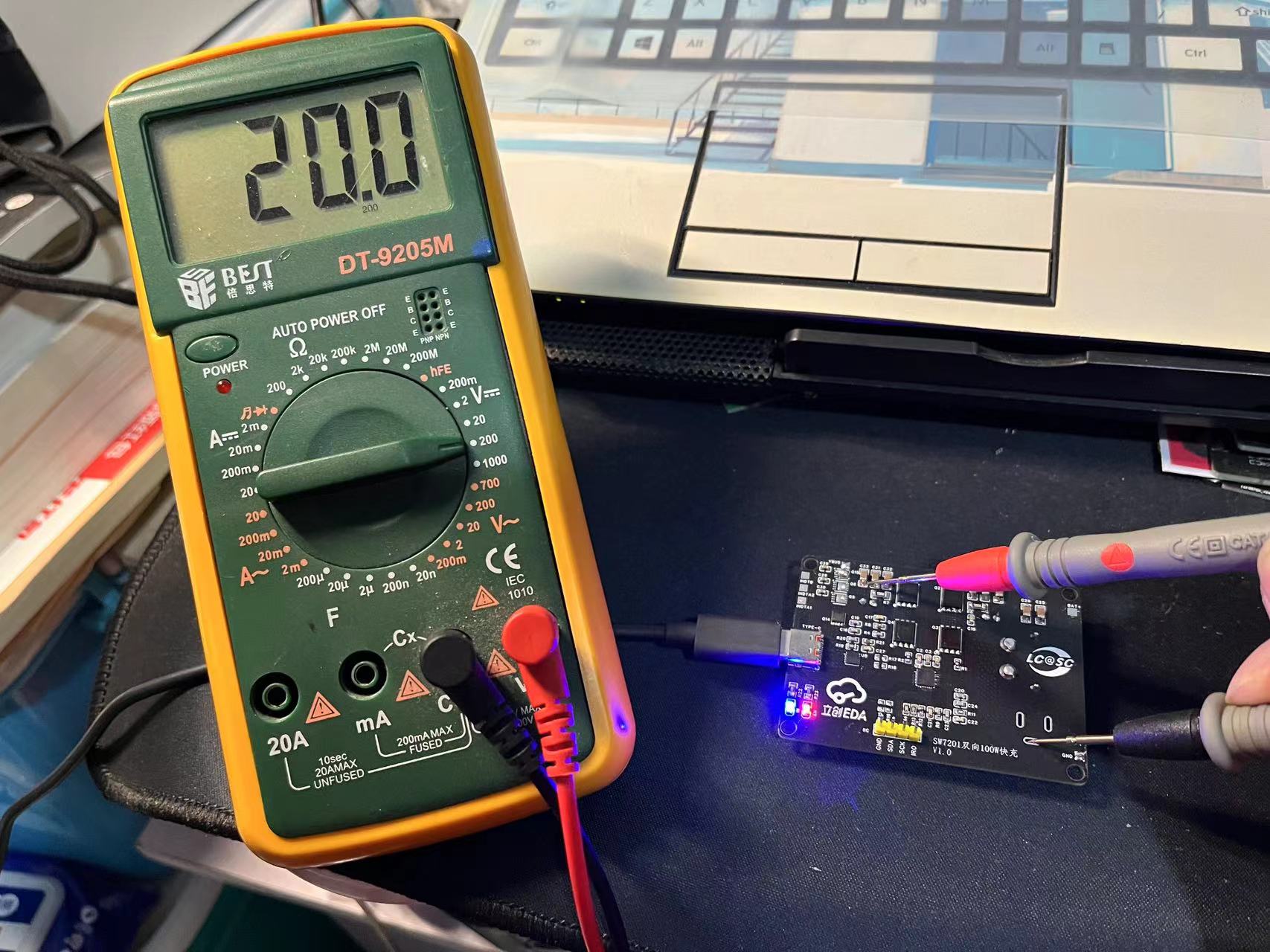
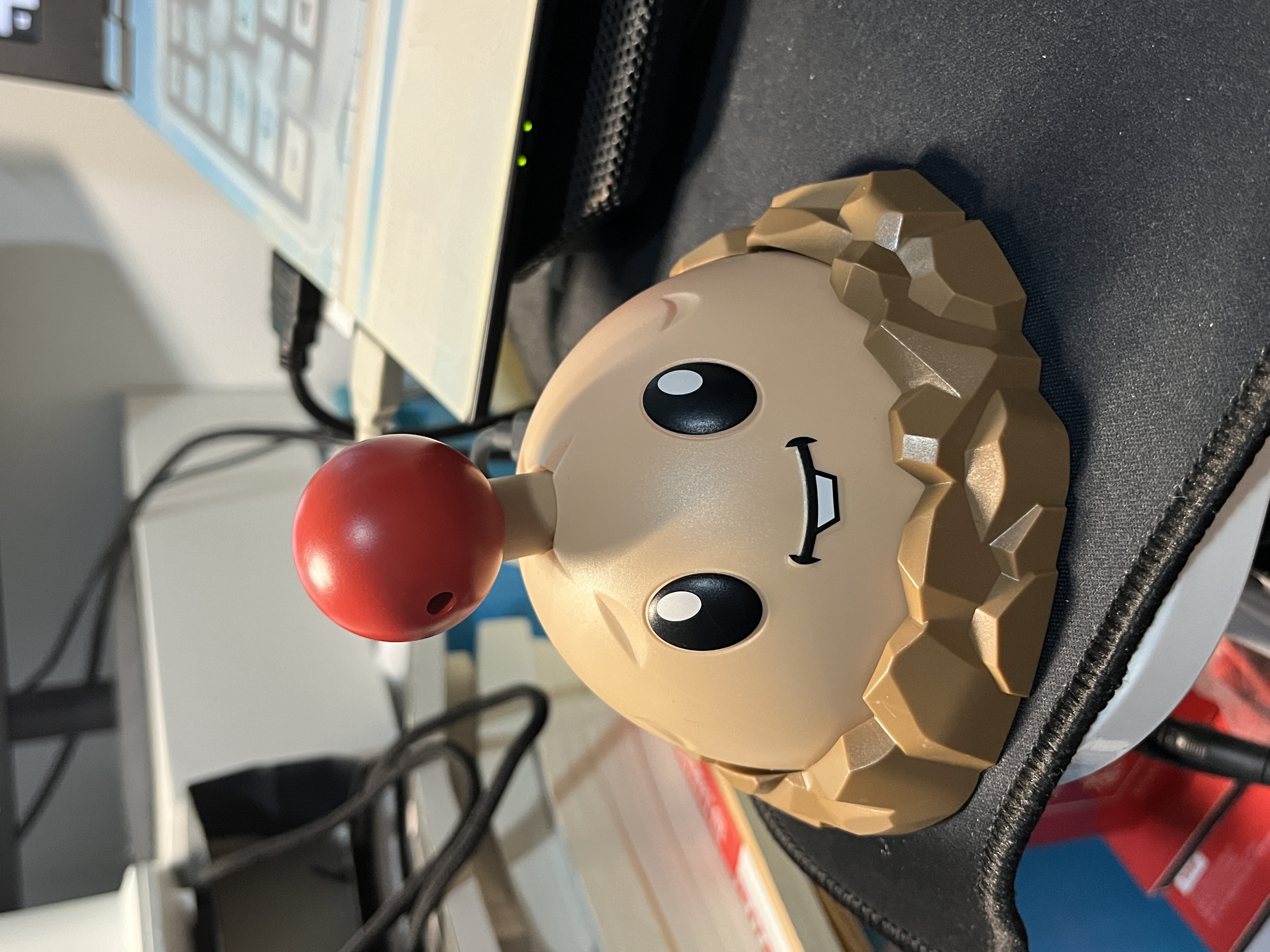
"Potato Mine Bomb" - Based on Zhirong SW7201 bidirectional fast charging
This portable backup power supply, based on the Zhirong SW7201 high-efficiency bidirectional buck-boost charge/discharge controller, was created as an April Fool's Day project in 2024. Its outer casing resembles the potato mine from Plants vs. Zombies, but it's actually a portable fast-charging power bank.
The SW7201 is a high-efficiency synchronous 4-tube bidirectional buck-boost charge/discharge controller that supports charge/discharge management of 1-4 batteries, supports I2C control, and can provide a maximum power output of 100W. This project uses the SW7201 as the lithium battery management chip and the HSUB238 PD decoy chip to fast charge the lithium battery. It can also output 20V5A/100W of energy, enabling charging of electronic products such as laptops and mobile phones when you are out and about.
SW7201 Chip Introduction:
High-Efficiency Buck-Boost Switching Charge:
➢ Supports buck-boost charging of 1 to 4 lithium batteries, including complete charging cycle management
➢ Supports 3V-19.2V charging target voltage setting, supporting various types of lithium batteries
➢ Supports 100W input power
➢ Supports 4V-24V input voltage
➢ Supports I2C programmable control of input/battery current limiting
➢ Seamless switching between boost and buck
Reverse Buck-Boost Discharge:
➢ Supports 100W output power
➢ Supports 3V-22V output voltage
➢ Flexible selection of FB/I2C voltage regulation
➢ Supports I2C programmable control of output current limiting
➢ PFM/PWM mode automatically switches according to load size
The chip has a built-in 12-bit ADC.
The battery side uses one XT60 model aircraft interface and one DC005 interface, with reserved output pads for connecting other interfaces. The number
of lithium batteries (1-4) can be selected by configuring the BSSTT resistor on the chip; the inductor can be a high-power inductor ranging from 1 to 4.7uH, with different inductor COMP parameters corresponding to different resistors and capacitors.
Currently, four 4500mAh 21700 lithium batteries from Dongci are used as the battery terminals, and the charge/discharge rates meet the requirements.
The physical

PD decoy chip HUSB238 decoys 20V input
/output

. The accompanying video demonstrates using an electronic load to drive 60W and switching between different voltage levels. If using high-power loads for extended periods, a fan cooling system is still necessary, which will be considered for internal cooling in the future. Since there is only one color silkscreen roll, and black ink is currently being used for color printing, there is concern about wasting ink if the first printout is not done well. With successful verification, color proofing can now be enjoyed. Thanks to LCSC for their support of this event; we have gained valuable experience from this experience.
Switching voltage levels.mp4
Loading.mp4
PDF_“Potato Mine Bomb” - Bidirectional Fast Charging Based on Zhirong SW7201.zip
Altium_“Potato Mine Bomb” - Based on Zhirong SW7201 Bidirectional Fast Charging.zip
PADS_“Potato Mine Bomb” - Bidirectional Fast Charging Based on Zhirong SW7201.zip
BOM_“Potato Mine Bomb” - Bidirectional Fast Charging Based on Zhirong SW7201.xlsx
90956
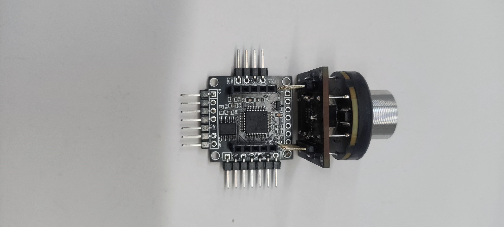
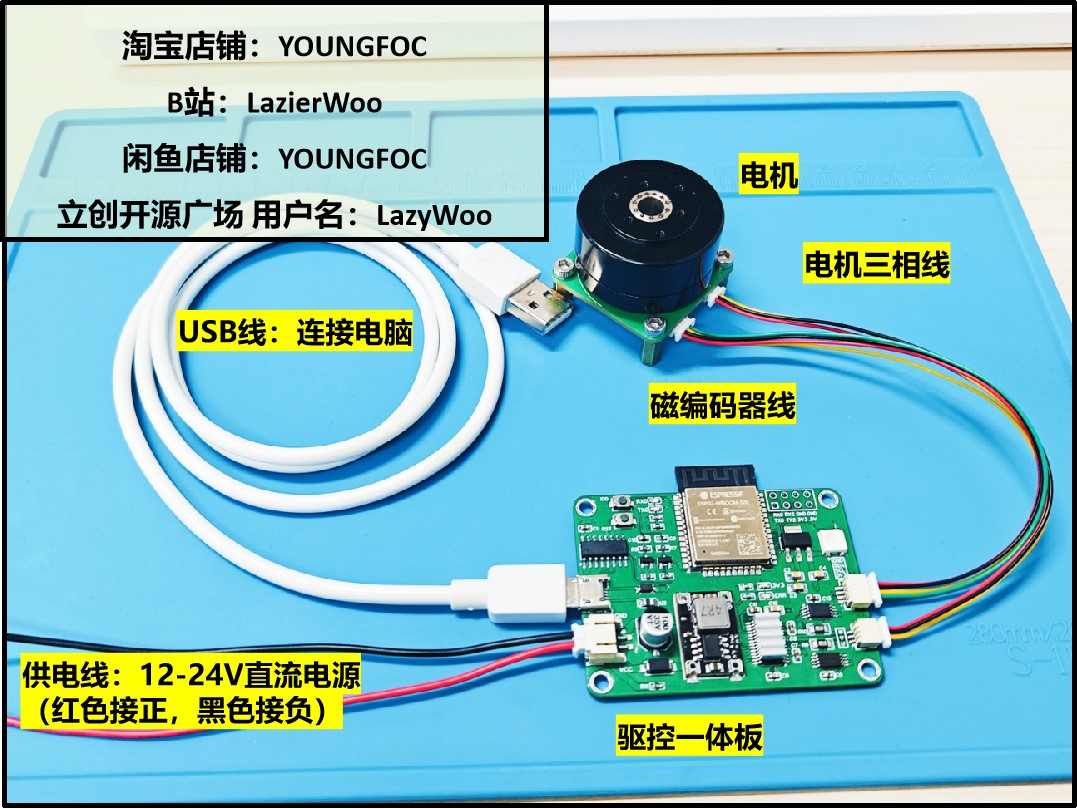
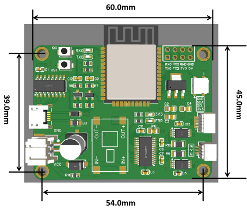
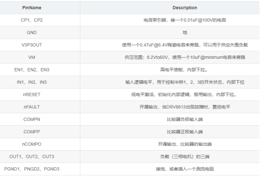
SimpleFOC_X Brushless Motor Drive and Control Integrated Board (Verified - Professional Version)
SimpleFOC_X is an open-source SimpleFOC driver and controller integrated board. It uses ESP32 as the main controller, DRV8313 integrated driver chip, INA240A2 current detection, and supports three closed-loop control: current loop, speed loop, and position loop.


1. Specifications and Specifications:
The integrated driver board features an ESP32-WROOM-32E module with a high clock speed of 240MHz, delivering powerful performance. It includes Bluetooth and Wi-Fi, enabling various applications. The brushless motor driver chip is a DRV8313PWPR, with a peak current of up to 2.5A (@25°C@24V, continuous operation requires less than 1.5A). It employs an inline current sampling scheme, using the INA240A2 as the sampling chip, with a 0.01 ohm sampling resistor and a 50V/V amplification factor. The sampleable current range is -3.3A to 3.3A. A CH340C chip is integrated on the board for USB-to-serial communication and program downloading. An onboard automatic download circuit eliminates the need for manual reset during the download process. LED indicators provide overcurrent protection, short-circuit protection, undervoltage lockout, and overtemperature protection. An onboard DC-DC step-down module outputs 5V, and an AMS117-3.3V linear regulator outputs 3.3V. The board is also equipped with a reverse connection protection diode to prevent the power line from being reversed. The onboard WS2812B full-color LED can realize full-color light display.

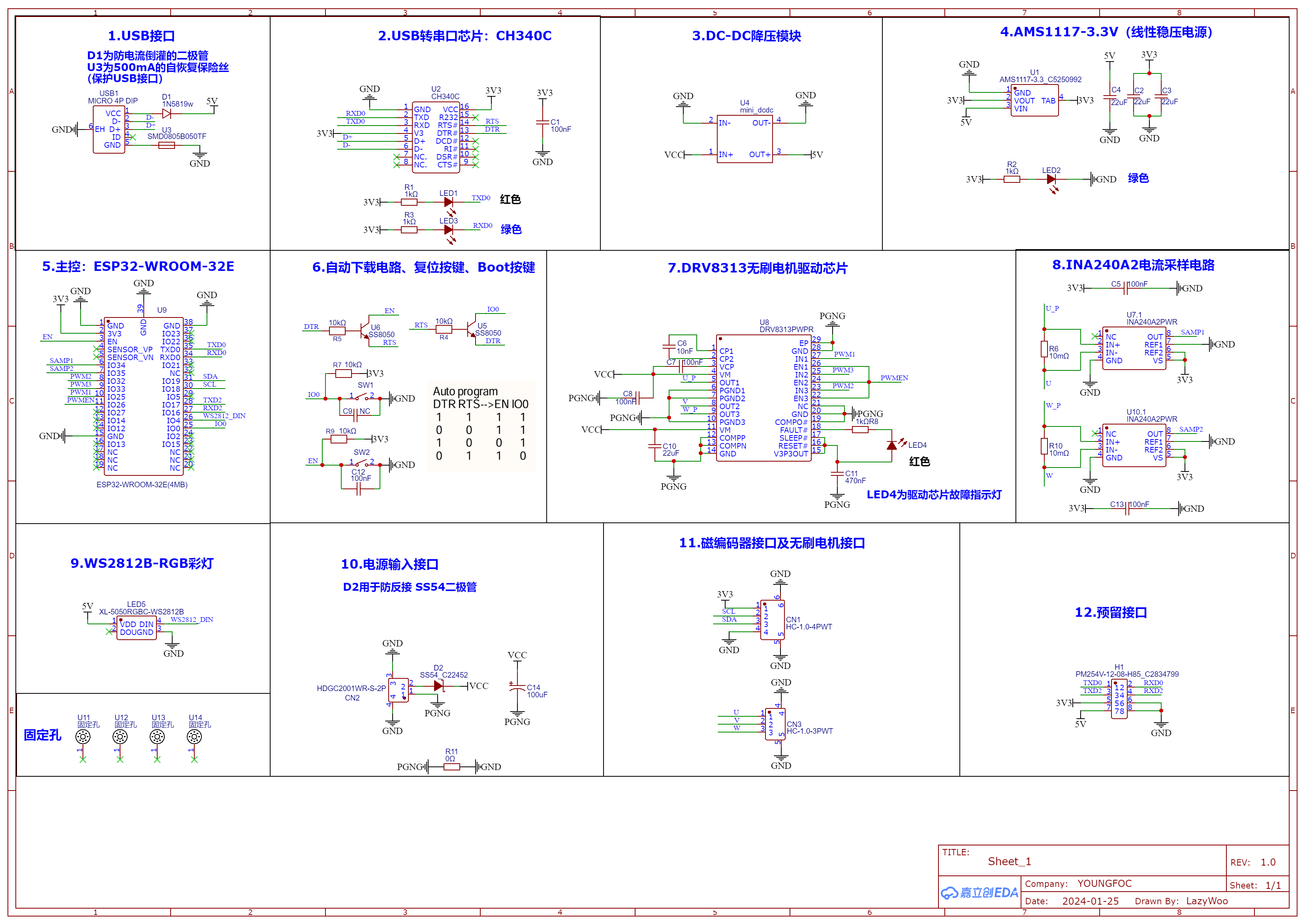
2. Schematic diagram introduction
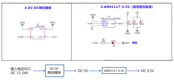
2.1 Power supply scheme
The power supply scheme is shown in the figure below. The input voltage of SimpleFOC_X V1.0 is 12-24V DC voltage input. The reverse connection protection diode can prevent the DC power supply from being reversed and damaging the circuit, but it will cause a certain degree of voltage drop. The SS54 diode has a voltage drop of about 0.5V when it is fully loaded at 5A, but in this application scenario, the current cannot reach 5A, and its voltage drop is about 0.3V. When setting the power supply voltage in the program, you can subtract 0.3V from the input voltage to get the VCC voltage (which can also be ignored).

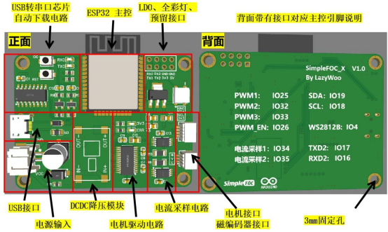
2.2 Introduction of each part
(1) USB interface
USB Micro interface;
(2) USB to serial port circuit
The USB to serial port chip uses CH340C. To adapt to the ESP32 level, a 3.3V power supply is used. The VCC and V3 pins are both connected to the 3.3V level. A 100nF capacitor is used for decoupling. The RTS and DTR pins are used for the ESP32 automatic download circuit.
(3) (4) Step-down module and linear regulated power supply
(5) (6) Main controller: ESP32-WROOM-32E and automatic download circuit

(7) DRV8313 brushless motor driver chip
DRV8313 provides internal shutdown functions to realize overcurrent protection, short circuit protection, undervoltage lockout and overtemperature protection. When the LED4 fault light is on, the power should be turned off immediately and the cause of the error should be eliminated before powering on again. When only USB is connected and DC power is not connected, the fault light is lit due to undervoltage, which can be ignored. After powering on, the fault light will automatically turn off.
The maximum current of DRV8313 is 2.5A (peak current) @25°C @24V. It cannot work for a long time at a current exceeding 1.5A.
(8) INA240A2 Current Sampling Circuit
INA240 has enhanced PWM suppression function and is an excellent choice for built-in current detection. Built-in current detection (Inline CurrentSense) is the simplest and most accurate technology to use. The sampling resistor is connected in series on the motor phase line. The detected current is always the motor phase current. Because the current in the inductor will not change abruptly, the sampled current is continuous and stable regardless of the state of the PWM duty cycle.

The motor current is a sine wave. For the sampled differential signal, the negative half-cycle is negative. For easy processing, a bias voltage needs to be superimposed to ensure that the output of the whole cycle is positive.
(9) WS2812B-RGB Color Light
(10) Power Input Interface
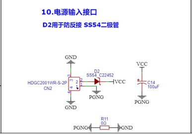
Input voltage: DC 12-24V. D2 is used for reverse connection protection. D2 can withstand a maximum positive current of 5A, but there is a voltage drop of 0.5V under full load and about 0.3V during low current use. VCC = input voltage - 0.3V.
C14 is used for energy storage, and R11 is a 0Ω resistor used to isolate the motor PGND and digital GND.
(11) Magnetic encoder interface and brushless motor interface
The magnetic encoder interface is an I2C interface, powered by 3.3V, used to connect the AS5600 magnetic encoder.
U, V, and W are connected to the three-phase lines of the brushless motor.
(12) Reserved interfaces
The reserved interfaces include serial port 0 and serial port 2.
Demo video.mp4
PDF_SimpleFOC_X Brushless Motor Drive and Control Integrated Board (Verified Professional Version).zip
Altium SimpleFOC X Brushless Motor Driver and Control Board (Verified Professional Version).zip
PADS_SimpleFOC_X Brushless Motor Drive and Control Integrated Board (Verified Professional Version).zip
BOM_SimpleFOC_X Brushless Motor Drive and Control Integrated Board (Verified Professional Version).xlsx
90957
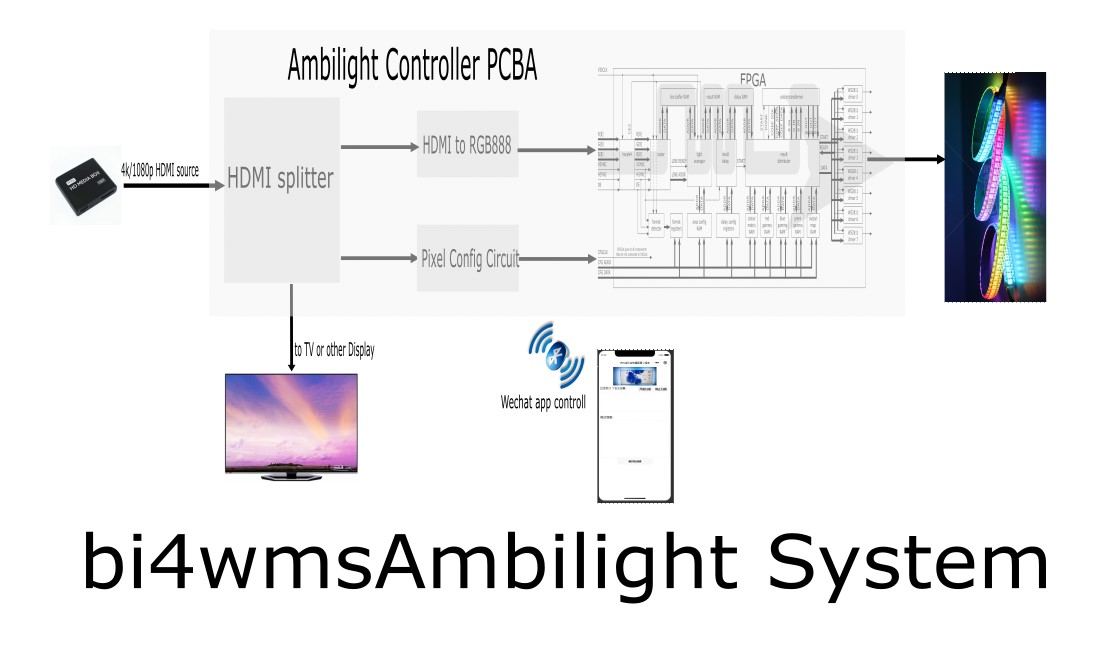
FPGA Radiant Controller
An FPGA hardware-implemented light and color controller, with LED configuration via WeChat mini-program, integrated HDMI splitter, supports HDMI input, 1080p/4K video, and WS2812, WS2815 and other series of LED strips.
This project describes
a video ambient lighting control system. It controls the color of the LED strip on the TV bezel based on the color of the edges of the video signal, creating a smooth visual transition and an atmosphere where the video content blends seamlessly with the surrounding environment.
Currently, commercially available systems primarily use Philips' Ambilight series TVs and the Hue system. Common open-source projects often involve complex software installations via Raspberry Pi or PC, requiring numerous configuration steps and hardware conversions. Their core principle involves capturing video streams from the network, analyzing and calculating the stream, extracting color information, and finally controlling programmable LEDs via GPIO ports or USB-to-serial adapters. This project's advantage lies in its simple device—requiring only a single controller for plug-and-play operation. The former approach has obvious drawbacks: complex hardware and software configurations, and the sequential processing of the software inevitably leads to a lag between the ambient light color and the video signal generation. This system, implemented using FPGA pure hardware circuitry, eliminates the delay caused by sequential software execution, resulting in a more seamless video ambient lighting experience. The project
is licensed
under the CERN Open Hardware License. Key
features include:
1) Integration of an HDMI 1-to-2 splitter controller, supporting mainstream 1080p and 4K@60Hz refresh rates;
2) Simultaneous support for 8 different LED strip configurations, controllable individually or in a splicing configuration;
3) Standard DC interface or stud terminal block wiring, 5-15V power input, compatible with WS2812 or WS2815 series LED strips;
4) Direct control of LED configuration via WeChat mini-program, adaptable to various application scenarios.
Project attributes:
This is the first public release of this project. It is an original project by the author and has not won any awards in other competitions.
Project Progress
2024-02-18 Design concept document complete
2024-02-22 Hardware engineering design in progress
2024-02-28 PCB completed, surface mount production
2024-03-15 Basic function debugging completed, can control light strip changes following video
2024-03-20 3D shell and sticker design completed
Design Principles
Hardware System Overall Design Block Diagram
Software Description
The software part is mainly divided into two parts
: 1. FPGA processing code, which references the open-source project https://github.com/esar/hdmilight-v2
2. LED scene configuration code, divided into controller configuration code and WeChat mini-program user interaction setting code.
The FPGA module interacts with the outside world through serial port commands. Several important serial port interface commands are referenced as follows:
Set Area -------- SA index xmin xmax ymin ymax divshift* index (0-255): The index or range of indices of the area definition(s) that should be set* xmin (0-63): The left most column of the area's rectangle* xmax (0-63): The right most column of the area's rectangle* ymin (0-63): The upper row of the area's rectangle* ymax (0-63): The lower row of the area's rectangle* divshift (0-): The number of places to right-shift the accumulated R, G and B value for the area, or in other words the divisor used to calculate the average * 1 = divide by 2 * 2 = divide by 4 * 3 = divide by 8 * etc.
Get Output Map-------------------------- GO output light* output (0-7): The index or indices of the output channels whose mapping should be retrieved* light (0-511): The index or indices of the LED(s) whose mapping should be retrieved
Set Output Map-------------------------- SO output light area color gamma enable* output (0-7): The index or indices of the output channels whose mapping should be set* light (0-511): The index or indices of the LED(s) whose mapping should be set* area (0-255): The index of the area definition that the LED(s) should use* color (0-15): The index of the color matrix that the LED(s) should use* gamma (0-7): The index of the gamma table that the LED(s) should use* enable (0-1): * 1 = enabled * 0 = disabled
Key code for interaction between MCU and FPGA on the controller board
void SetLightToFrame(int LightNO, uint16_t yLEFT, uint16_t xUP, uint16_t yRIGHT, uint16_t xDOWN){
for (int i = 0; i { setOutput(LightNO, i, map(i, 0, yLEFT - 1, 32, 0))); }
for (int i = yLEFT; i { setOutput(LightNO, i, map(i, yLEFT, yLEFT + xUP - 1, 33, 92)); }
for (int i = yLEFT + xUP; i { setOutput(LightNO, i, map(i, yLEFT + xUP, yLEFT + xUP + yRIGHT - 1, 93, 125)); }
for (int i = yLEFT + xUP + yRIGHT; i { setOutput(LightNO, i, map(i, yLEFT + xUP + yRIGHT, yLEFT + xUP + yRIGHT + xDOWN - 1, 185, 126)); }}
Key code for interaction between the MCU and WeChat mini-program on the controller board
// Create the BLE Device BLEDevice::init("Radiant Controller");
// Create the BLE Server pServer = BLEDevice::createServer(); pServer->setCallbacks(new MyServerCallbacks());
// Create the BLE Service BLEService *pService = pServer->createService(SERVICE_UUID);
// Create a BLE Characteristic pTxCharacteristic = pService->createCharacteristic( CHARACTERISTIC_UUID_TX, BLECharacteristic::PROPERTY_NOTIFY );
pTxCharacteristic->addDescriptor(new BLE2902());
BLECharacteristic * pRxCharacteristic = pService->createCharacteristic( CHARACTERISTIC_UUID_RX, BLECharacteristic::PROPERTY_WRITE );
pRxCharacteristic->setCallbacks(new MyCallbacks());
// Start the service pService->start();
// Start advertising pServer->getAdvertising()->start();
Key code for interaction between WeChat applet and onboard MCU
//index.js
//Get application instance
const app = getApp()
function inArray(arr, key, val) {
for (let i = 0; i
if (arr[i][key] === val) {
return i;
}
}
return -1;
}
// Example of converting ArrayBuffer to hexadecimal string
function ab2hex(buffer) {
var hexArr = Array.prototype.map.call(
new Uint8Array(buffer),
function (bit) {
return ('00' + bit.toString(16)).slice(-2)
}
)
return hexArr.join('');
}
// ASCII code to hexadecimal
function strToHexCharCode(str) {
if (str === "") {
return "";
} else {
var hexCharCode = [];
hexCharCode.push("0x");
for (var i = 0; i
hexCharCode.push((str.charCodeAt(i)).toString(16));
}
return hexCharCode.join("");
}
}
// String to byte
function stringToBytes(str) {
var array = new Uint8Array(str.length);
for (var i = 0, l = str.length; i
array[i] = str.charCodeAt(i);
}
console.log(array);
return array.buffer;
}
Page({
data: {
devices:[],
connected: false,
chs: [],
sendData:"",
logs: [],
dataType: true,//false: HEX type,true: ASCII type
},
printLog:function(log) {
var logs = this.data.logs;
logs.push(log);
this.setData({log_list: logs.join('
')})
},
printInfo:function(info) {
wx.showToast({
title: info,
icon: 'none',
duration: 1200,
mask: true
})
},
// Start device discovery function
startBluetoothDevicesDiscovery() {
if(this._discoveryStarted) {
this.printLog("Discovering devices...")
return
}
this._discoveryStarted = true
wx.startBluetoothDevicesDiscovery({
allowDuplicatesKey: true,
success: (res) => {
this.printLog("Starting to discover devices...")
this.onBluetoothDeviceFound()
},
})
},
// Stop device discovery function
stopBluetoothDevicesDiscovery() {
this.printLog('Stop discovering devices')
this._discoveryStarted = false
wx.stopBluetoothDevicesDiscovery()
},
// Finding devices
onBluetoothDeviceFound() {
this.printLog('Discovering devices...')
wx.onBluetoothDeviceFound((res) => {
res.devices.forEach(device => {
if (!device.name && !device.localName) {
return
}
const foundDevices = this.data.devices
const idx = inArray(foundDevices, 'deviceId', device.deviceId)
const data = {}
if (idx === -1) {
data[`devices[${foundDevices.length}]`] = device
} else {
data[`devices[${idx}]`] = device
}
this.setData(data)
})
})
},
// Creating a connection
bindcreateBLEConnection(e) {
const ds = e.currentTarget.dataset
const deviceId = ds.deviceId
const name = ds.name
this.printLog("Starting to connect to device [" + name + "]")
wx.createBLEConnection({
deviceId,
success: (res) => {
this.setData({
connected: true,
name,
deviceId, }) this.getBLEDeviceServices(deviceId) } }) // this.stopBluetoothDevicesDiscovery() }, // Disconnect closeBLEConnection () { this.printLog("Disconnected") this.printInfo("Successfully disconnected device") wx.closeBLEConnection({ deviceId: this.data.setData({ connected: true, name, deviceId,
} )
this.getBLEDeviceServices (deviceId) } }) // this.stopBluetoothDevicesDiscovery() }, // Disconnect closeBLEConnection() { this.printLog("Disconnected") this.printInfo("Successfully disconnected device") wx.closeBLEConnection({ deviceId: this.data.setData ({ connected: true, name, deviceId, }) } }deviceId }) this


 京公网安备 11010802033920号

 MHM55-9761-FB


