Update
2023-12-01: Remeasured BEC load, 5V_1.5A/9V_1.5A (free prototyping, inner copper thickness 0.5oz).
2023-12-14: LXBSZ renamed LXBRC, PCB layout optimized, silkscreen markings improved.
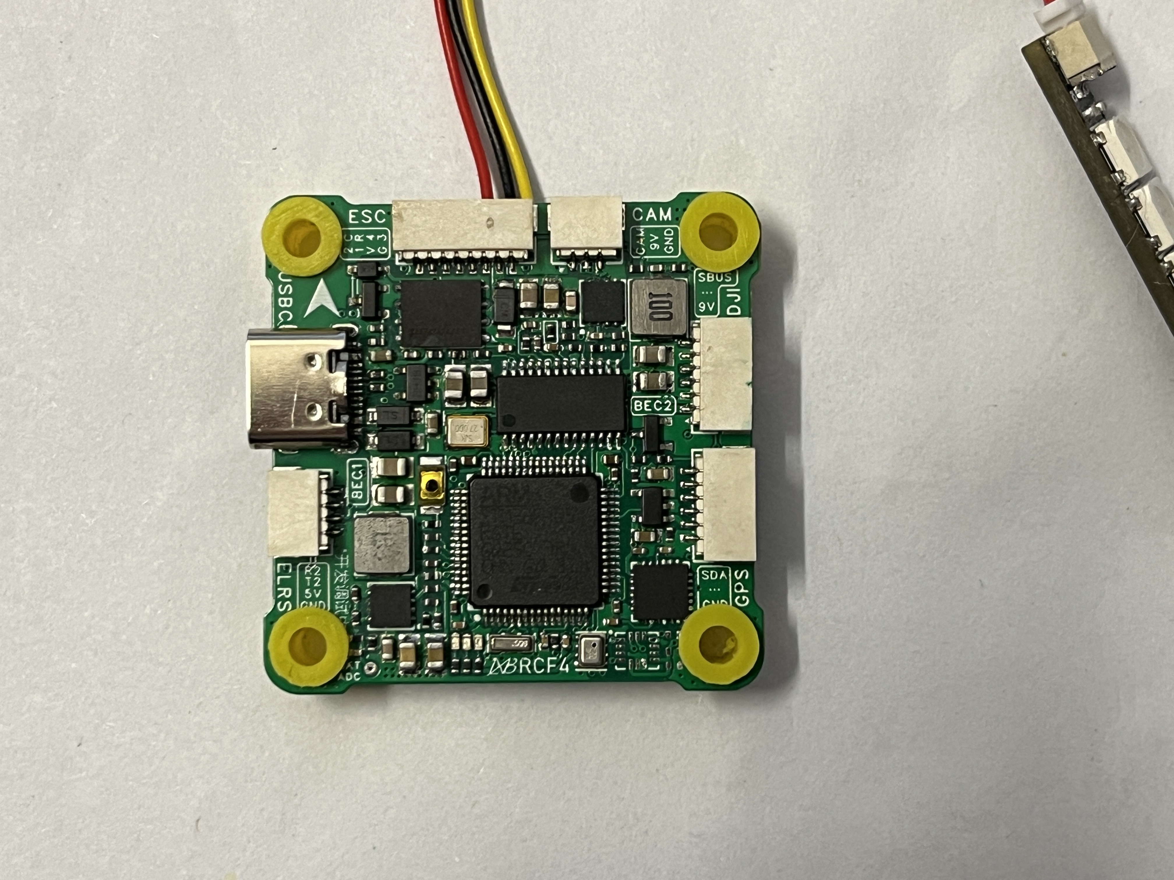
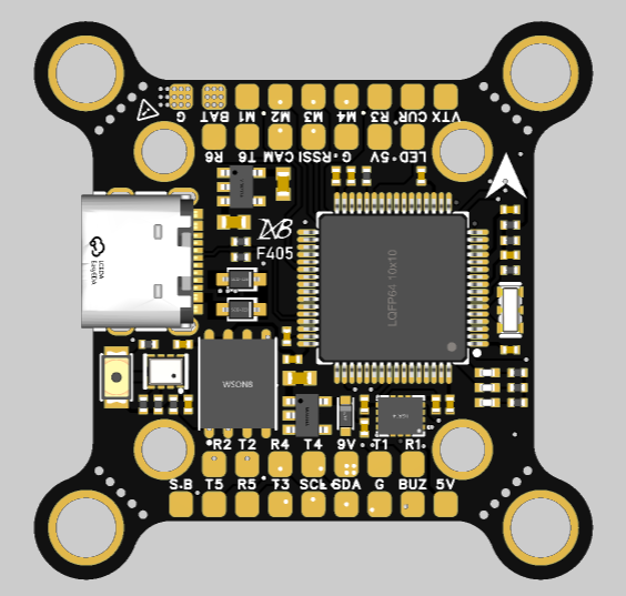
This describes
a DIY F4 flight controller with a single-sided board (I didn't want to solder both sides). Soldering only one side and placing it on a heating plate is convenient.
The hardware connection is based on the HGLRC configuration. (Please contact me to remove if there is any copyright infringement).
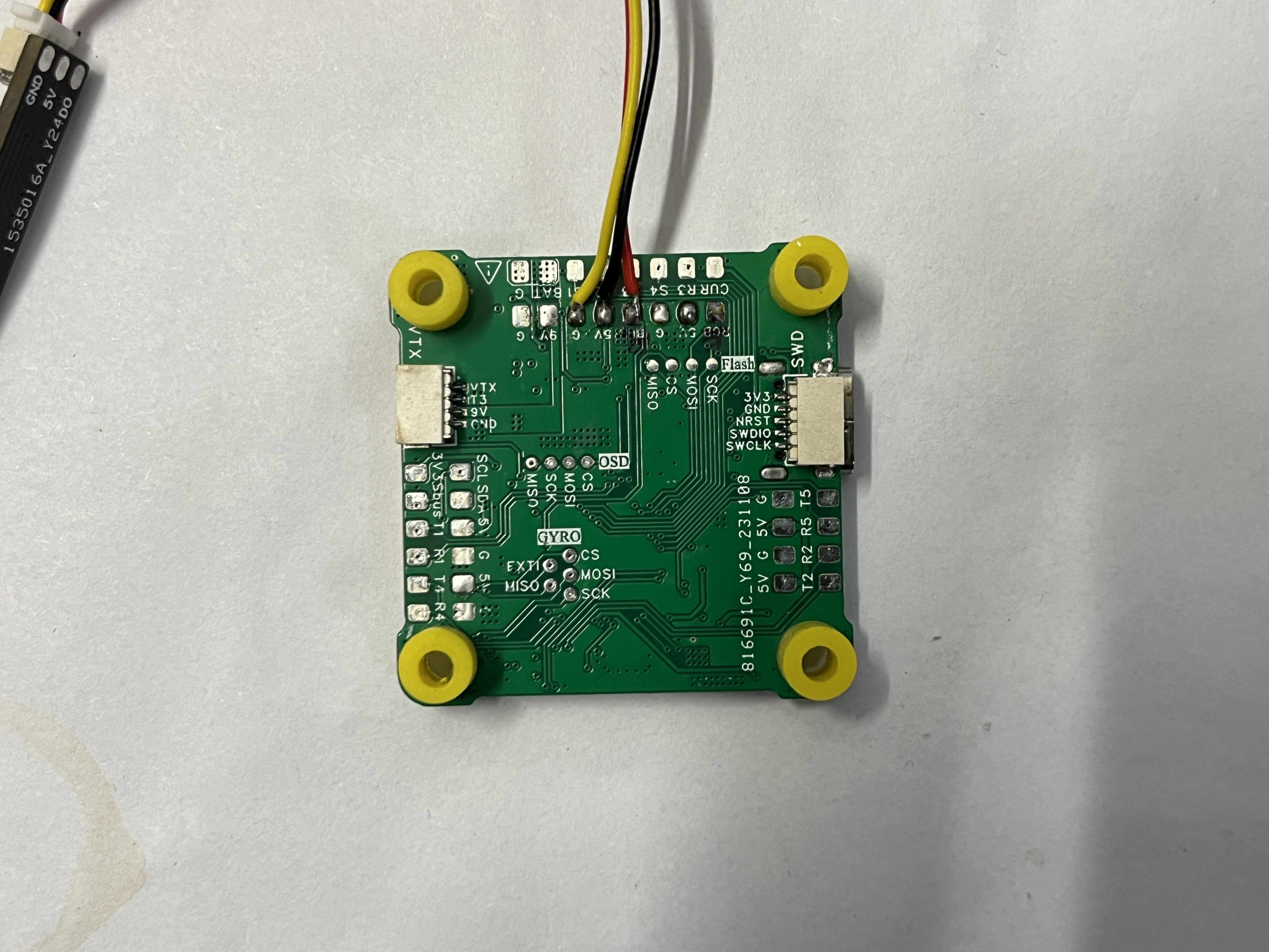
The pads are all on the back; the front is all through-hole, which I find simple and convenient.
An SWD interface is provided for secondary development, allowing flashing Betaflight firmware or my own flight controller program.
I'm a beginner in electronics, and the PCB layout and routing need improvement. Experts are welcome to share their opinions and help improve it. Thank you very much!
Configuration:
Main MCU: STM32F405RGT6
, Main Frequency: 168MHz;
Gyroscope: MPU6000 (measured) / ICM_42688P (unmeasured) / BMI270 (unmeasured);
OSD: AT7456E
; Black Box: 16M
; Barometer: BMP280;
UART: 5 Sets;
Receiver: SBUS/ELRS;
DJI Interface: Yes;
GPS Interface: Yes;
RGB: Yes;
ESC Signal: 4 Sets;
BEC: 5V_1.5A/9V_1.5A;
TVS Protection: Yes;
Input: 2S~6S;
Mounting: 30.5×30.5mm/M3;
Size: 37.415×37.415mm;
Weigt: 7g;
Firmware :
HGLRCF405V2 .
Cost
is approximately 70 RMB. See the attachment for specific component costs.
A mini version (30*30/20*20) is currently being designed. Please stay tuned.
test.mp4
LXBSZ Cost.xlsx
Gerber_LXBRC-F405_V1.1_2024-03-17.zip
HAKRCF405V2_config.h
PDF_LXBRC-STM32F405 Flight Controller.zip
Altium_LXBRC-STM32F405 flight controller.zip
PADS_LXBRC-STM32F405 flight controller.zip
BOM_LXBRC-STM32F405 Flight Controller.xlsx
93111
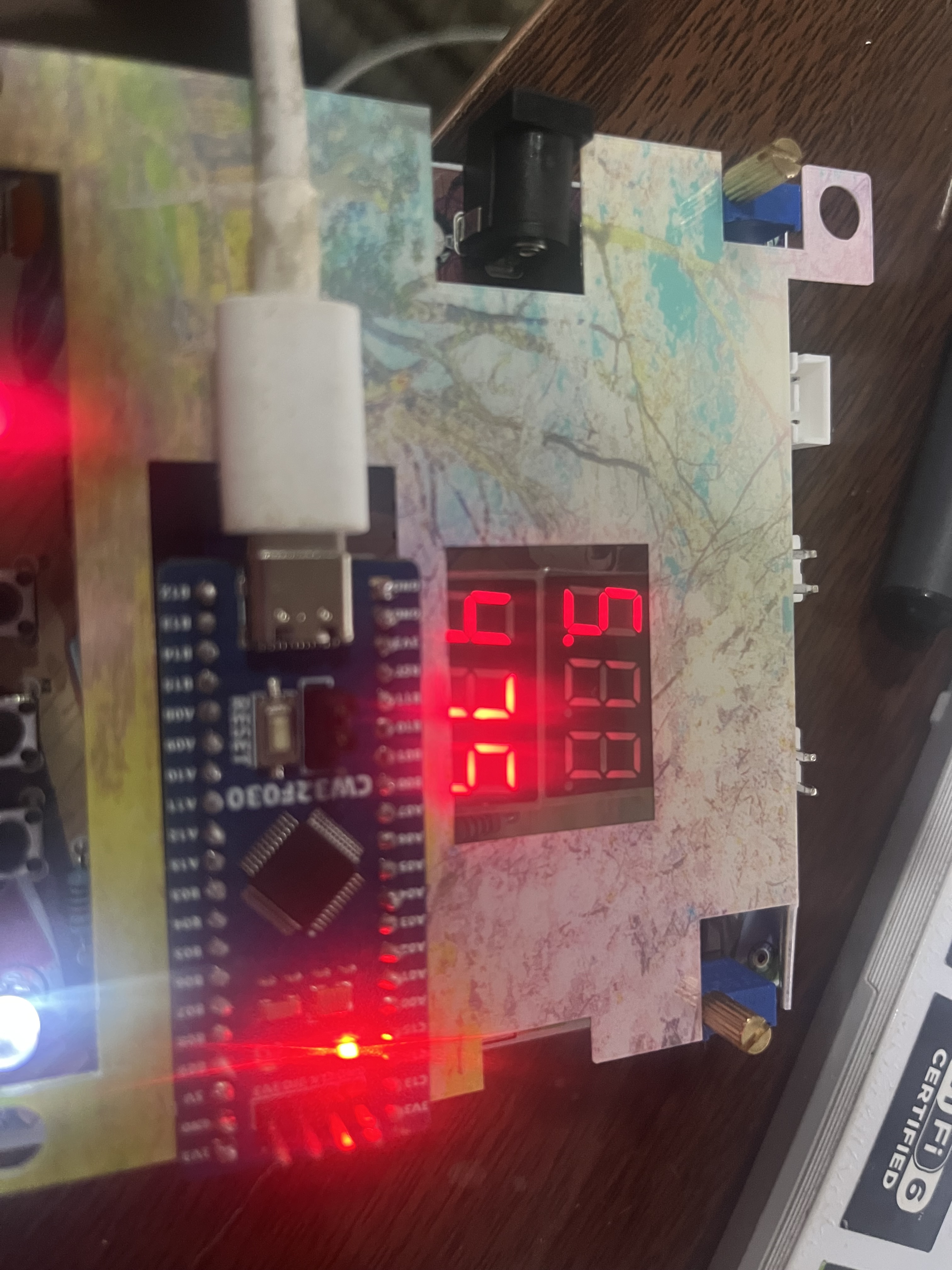
Simple voltmeter and ammeter
Simple voltage and current meter based on LCSC Diwenxing development board
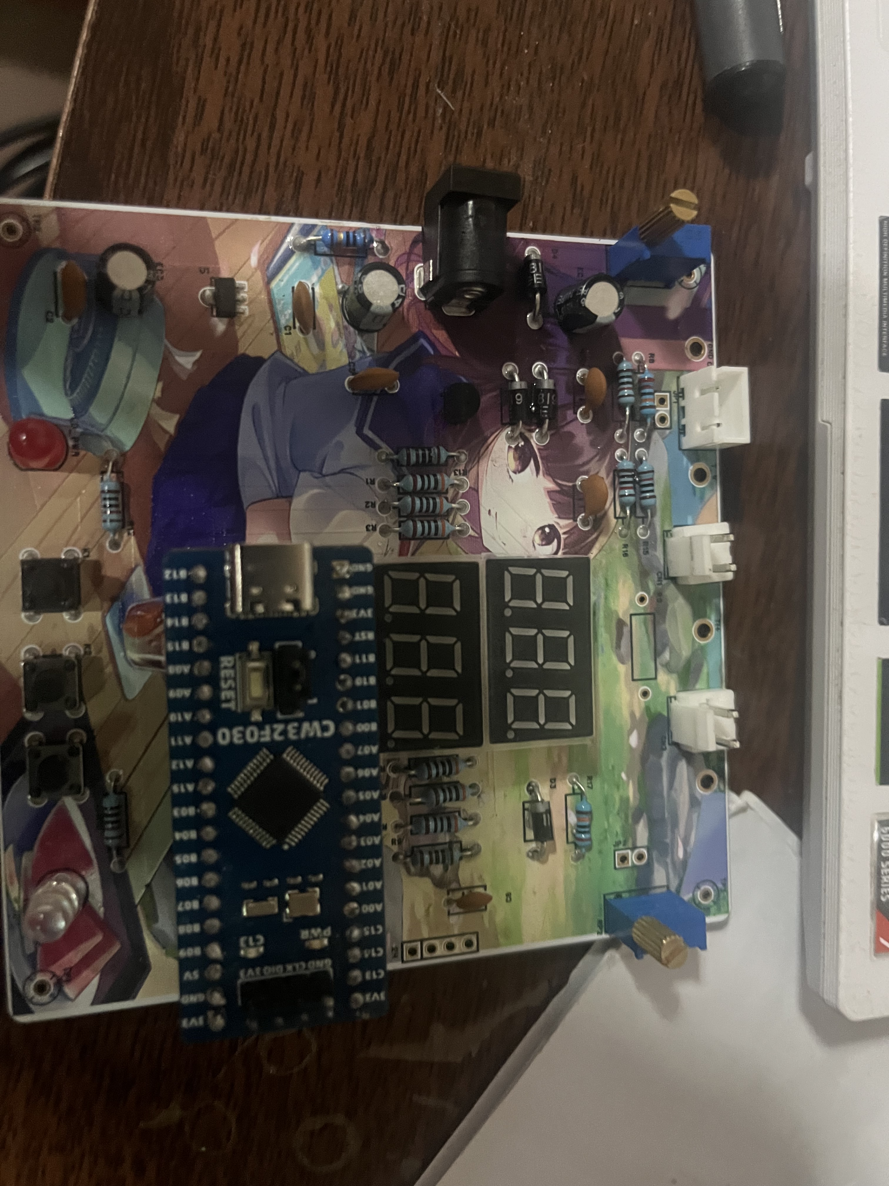
1. Project Function Introduction and
Finished Product Images:
2. Project Attributes:
This project is a replica of the open-source project from the training camp.
3. Open Source License:
GPL 3.0
4. Minor Bug:
The last two digits of the digital tube display are always unclear and the light is very dim. I suspected it was due to a cold solder joint, but after resoldering it, the problem persists.
It shouldn't be a code issue, since the downloaded code also has this problem.
My multimeter isn't very reliable either; it can't accurately measure resistance. I'll buy another one when I get back to school.
5. Project Demo:
I used LCSC to draw a simple outer shell and panel.
Simple Voltmeter and Ammeter.rar
BOM_Board1_PCB1_2024-08-02.xlsx
3DShell_PCB1.zip
PDF_Simple Voltage and Current Meter.zip
Altium Simple Voltage and Current Meter.zip
PADS_Simple Voltage and Current Meter.zip
BOM_Simple Voltage and Current Meter.xlsx
93112
Wireless Daplink based on ESP32C3
The DAPLink wireless chip, based on the ESP32C3 microcontroller, uses open-source firmware and is compatible with various C3 chips.
This project is not recommended for replication at this time!
For specific usage instructions, please refer to (ฅ>ω
or windowsair/wireless-esp8266-dap: CMSIS-DAP compatible wireless debugger, suitable for various ESP chips such as ESP8266, ESP32. Optional 40MHz SPI acceleration, etc. Wireless debugger compatible with multiple ESP chips--- windowsair/wireless-esp8266-dap: CMSIS-DAP compatible wireless debugger for various ESP chips such as ESP8266, ESP32. Optional 40MHz SPI acceleration, etc. Wireless debugger compatible with multiple ESP chips (github.com)
or Wireless DAP-LINK User Guide | Yunsi Studio (yunsi.studio).
We recommend using the first firmware (actually the second one). The last firmware can be referenced for debugging methods, but it runs a web application and simultaneously opens a hotspot, resulting in higher power consumption and causing severe overheating, triggering overheat protection within minutes.
The 662k chosen by LDO might be a bit overwhelmed by the power consumption of C3, resulting in significant heat generation, but it can still be used stably, so don't worry about it. If you're concerned, you can replace it with ME6231A33M3G; no board modifications are needed.
Ignore the P2P DRC replacement error; that's caused by the PCB antenna package. The board assembly is fine. There are
several types of C3 chips: ESP32C3/ESP32C3FN4/ESP32C3FH4. When using C3, solder an external flash memory; when using FN4/FH4, do not solder an external flash memory (the power supply filter capacitor can also be omitted).
Remember to hold down the boot button before powering on when downloading programs .
Below are some issues with this project:
The board verification is fine; it can connect to the computer's hotspot normally, but it cannot connect to the Keil virtual debugger. We are looking for the cause, and we suspect it might be related to the FN4/FH4. Insufficient flash memory or overheating of the 662k chip causing unstable connections.
The original firmware lacks a Wi-Fi to serial port function, but I have reserved a serial port. Experienced developers are welcome to modify the firmware to enable serial port
functionality. Currently, only SWD and JTAG are supported; I abandoned them due to wiring issues.
Important note:
Do not use this board to power other boards. The LDO chip is very small, so powering other boards will easily burn it out. Always use a different PCB for power.
External flash memory is only needed when using C3; the other two chips have built-in flash memory. After soldering external flash memory... If the computer cannot recognize the chip
during the programming process, refer to the blog mentioned above. No additional software is needed when using Yuns Studio firmware for programming; other firmware requires additional software.
It's best to equip the C3 chip with a heatsink, as its power consumption is quite high and it generates significant heat. Replacing it with an ME6231A33M3G power supply might reduce heat.
The board has a 3.3V voltage regulator and TVS protection for the Type-C port. If you are confident that there will be no electrostatic discharge (ESD) damage to the chip, you can omit these protection circuits. The
board is very small; header pins are not required, or you can use a simple 2x7 pin connector with 1mm spacing as the interface. Refer to the wiring diagram.

PDF_Wireless Daplink Based on ESP32C3.zip
Altium_wireless daplink based on ESP32C3.zip
PADS_wireless daplink based on ESP32C3.zip
BOM_Wireless Daplink Based on ESP32C3.xlsx
93113
electronic


 京公网安备 11010802033920号

 V375B15E375BL


