1. Schematic and board reference: http://vcc-gnd.cn/vcc_gnd/YD-RP2040-Lite. Modified from the core version of YD-RP2040-Lite, with pin compatibility but some component and board dimensions modified.
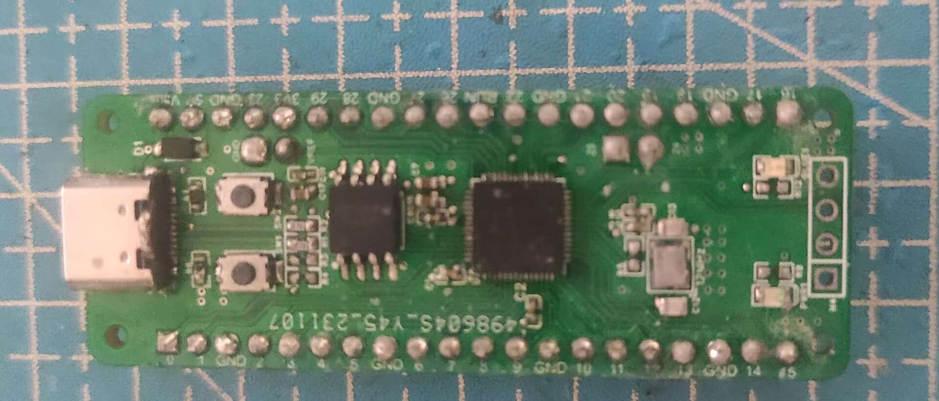

2. Used for RP2040 modular quadcopter control board (untested). Thanks to yanshimi (Yan Zong).

YD-RP2040-Lite-main.zip
PDF_RP2040 Development Board-V1.01.zip
Altium_RP2040 Development Board - V1.01.zip
PADS_RP2040 Development Board - V1.01.zip
BOM_RP2040 Development Board - V1.01.xlsx
94476
STM32F103VET6-PSRAM
The development board based on STM32F103VET6 has FLASH, PSRAM, EEPROM, TF, USART, and USB ports.
The development board based on STM32F103VET6 has FLASH, PSRAM, EEPROM, TF, USART, and USB ports.
Desktop.ioc
3a01588b2322891ad5e5cd5d34b5587.jpg
PDF_STM32F103VET6-PSRAM.zip
Altium_STM32F103VET6-PSRAM.zip
PADS_STM32F103VET6-PSRAM.zip
BOM_STM32F103VET6-PSRAM.xlsx
94477
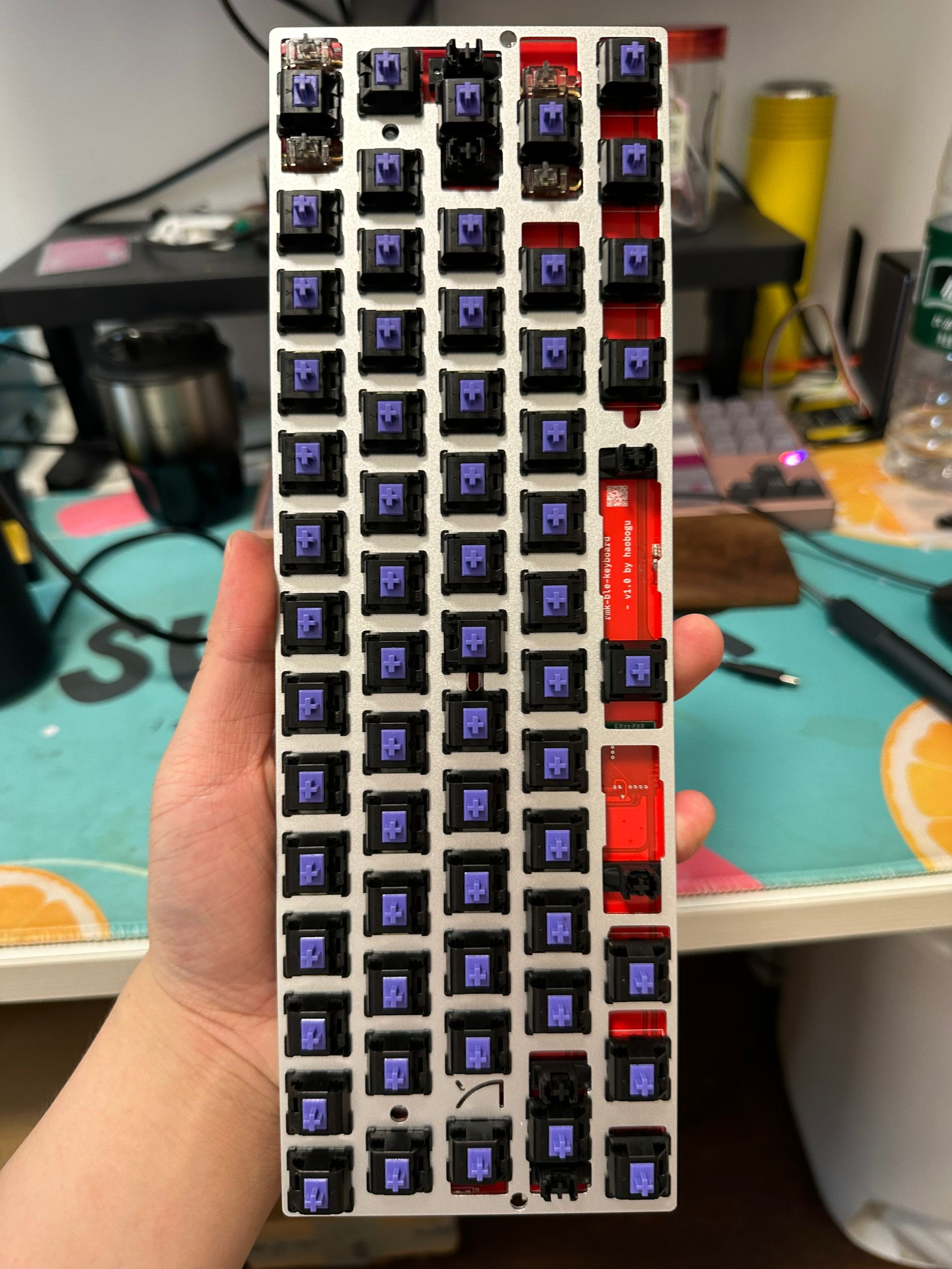
The GH60 Bluetooth keyboard is based on the E73 nRF52840 module.
This Bluetooth dual-mode keyboard, based on the nRF52840 E73 module, features fully open-source hardware and software, compatibility with the GH60 case, ultra-low latency, automatic BLE/USB switching, and VIAL online full-key remapping.
The rmk-ble-keyboard
is a Bluetooth dual-mode keyboard based on the nRF52840 E73 module. The firmware is written in Rust and supports automatic BLE/USB switching, VIAL key remapping, and other functions. It is compatible with the GH60 case and features ultra-low latency (10ms Bluetooth mode, 1.6ms USB).
Update: After importing from LCSC EDA, the PCB file curves will be lost. Therefore, the latest hardware version can be downloaded from the hardware repository. Welcome to star!
Successfully verified. Updated physical image:

Firmware
repository: rmk
Hardware repository: rmk-ble-keyboard
PDF_GH60 Bluetooth Keyboard Based on E73 nRF52840 Module.zip
Altium GH60 Bluetooth keyboard based on E73 nRF52840 module.zip
PADS_GH60 Bluetooth Keyboard Based on E73 nRF52840 Module.zip
94478
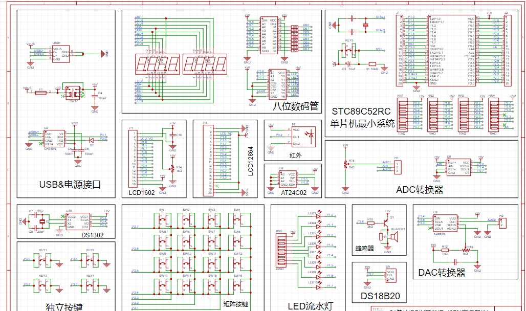
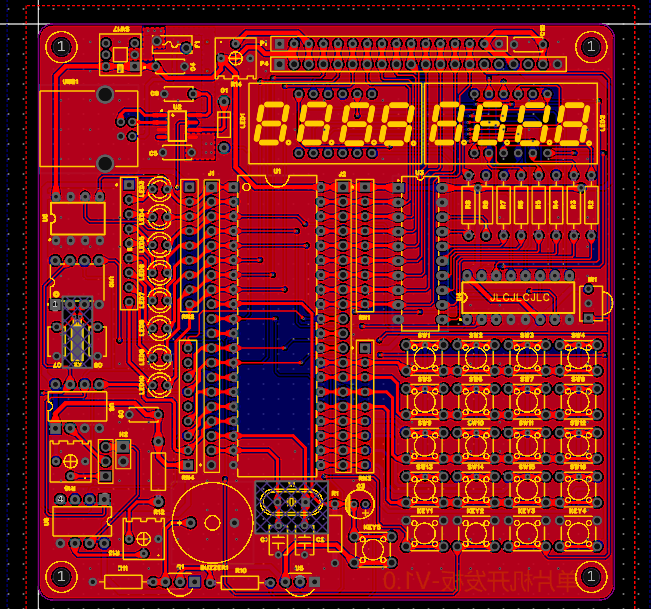
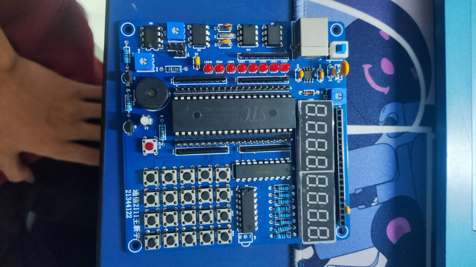
STC89C52 microcontroller development board
This 2-layer 51 microcontroller development board (excluding program) integrates multiple practical modules. Its completeness is second only to the official Puzhong development board, but it's smaller and suitable for basic microcontroller learning. While building your own board is slightly more expensive
, designing your own 51 microcontroller facilitates better learning.
The task requires a schematic design, PCB design, and physical demonstration
of a 2-layer 51 microcontroller development board integrating multiple practical modules.
PDF_STC89C52 Microcontroller Development Board.zip
Altium_STC89C52 microcontroller development board.zip
PADS_STC89C52 Microcontroller Development Board.zip
94479
STM32F103ZET6 Core Board
STM32F103ZET6 Core Board
The STM32F103ZET6 core board
test routine uses this developer's work: Microcontroller Minimum System Board - STM32F103VET6 - JLCPCB EDA Open Source Hardware Platform (oshwhub.com)

test routines.zip
20240530-182926.mp4
PDF_STM32F103ZET6-Core Board.zip
Altium_STM32F103ZET6-core board.zip
PADS_STM32F103ZET6-Core Board.zip
BOM_STM32F103ZET6-Core Board.xlsx
94480
Intelligent vehicle competition MP6528 dual-drive
Brushed dual-drive system for intelligent vehicle competitions, a replacement for DRV8701
The intelligent vehicle competition utilizes a brushed dual-drive system, employing Toshiba's low-resistance, high-current MOSFETs recommended by Zhuifei.
II. Design Summary
: A combination of AND and NOT gates is used to convert the control signal from EN/DIR to PWM A/B, supporting 24V motors.
Advantages compared to the DRV8701:
1. The MP6528 uses a trickle-charge circuit to ensure sufficient gate drive voltage during high-side drive, providing more stable performance and achieving 100% duty cycle.
2. The MP6528's adjustable dead-time control provides more flexible and precise protection settings, adapting to different application requirements and enabling it to operate well at higher drive signal frequencies.
III. Hardware Circuit Composition
: 3V3: An LDO is used to convert the input voltage to 3.3V, driving an LED as a power indicator, and simultaneously providing high-level signals to the MP6528's ENX and nSLEEP pins.
Logic Gate Section: The MP6528 uses PWMA/B as the drive signal input to control the motor's A/B terminals to be high or low. In this drive mode, controlling the forward and reverse rotation speed requires two PWM resources. To save PWM resources on the main MCU, the input is changed to EN/DIR signals (EN signal duty cycle sets the speed, DIR high/low level sets the direction). Logic gates are used to convert the EN/DIR signal into PWMA/B signals, which then control the MP6528.
Drive Section: The MP6528 controls the MOS of the H-bridge. The resistance value of the DT pin can set the dead time. A low nFAULT pin indicates an abnormal situation.
IV. Flowchart :
Logic Gate Flowchart

IV. Physical Demonstration

V. Precautions:
If MOS replacement is required, the capacitance value between BSTX and SHX (X is A/B) needs attention.
The capacitance value (nF) should be less than 1000nF and greater than 8 times Qg (nC), where Qg is the MOS's Total Gate Charge.
VI. Chip Datasheet
Official Website: https://www.monolithicpower.cn/cn/products/motor-drivers-and-motor-controllers/bldc-pre-drivers-and-integrated-solutions/mp6528.html
Datasheet Download Address: https://www.monolithicpower.cn/cn/documentview/productdocument/index/version/2/document_type/Datasheet/lang/en/sku/MP6528/document_id/3835/
VII. MPS University Program
The MPS China University Program, launched in 2018, closely follows the national
strategy of "New Engineering Construction." Starting from cutting-edge applied technologies and based on classic textbooks, it is committed to the organic integration of
higher education theory and practice, and dedicates itself to China's "Cultivation of Outstanding Engineers"
program. Currently, MPS has carried out various teaching, research, and competition support activities in many universities across the country
, and has been well received by teachers and students.
MP6528 samples can be applied for free on the MPS official website.
Scan the QR code to join the MPS University Program.

6528(1).jpg
PDF_Intelligent Car Competition MP6528 Dual Drive.zip
Altium_Intelligent Car Competition MP6528 Dual Drive.zip
PADS_Intelligent Car Competition MP6528 Dual Drive.zip
BOM_Intelligent Car Competition MP6528 Dual Drive.xlsx
94481
CH341A Multi-Voltage Dual-Mode Programmer (Replica and Modified Version)
The original open-source documentation can be found at https://oshwhub.com/misslee/ch341a-nextprogrammer
The original open-source documentation references https://oshwhub.com/misslee/ch341a-nextprogrammer, with some modifications to the package for easier soldering. All surface-mount components were placed on the top surface.
A simple test was conducted, and programming was successful, but the LED's operating mode was incorrect.

PDF_CH341A Multi-Voltage Dual-Mode Programmer (Replica Modified Version).zip
Altium CH341A Multi-Voltage Dual-Mode Programmer (Replica Modified Version).zip
PADS_CH341A Multi-Voltage Dual-Mode Programmer (Replica and Modified Version).zip
BOM_CH341A Multi-Voltage Dual-Mode Programmer (Replica Modified Version).xlsx
94482
LCSC Taishanpai Development Board - Android Mini Phone
Learn the Taishan School with the training camp
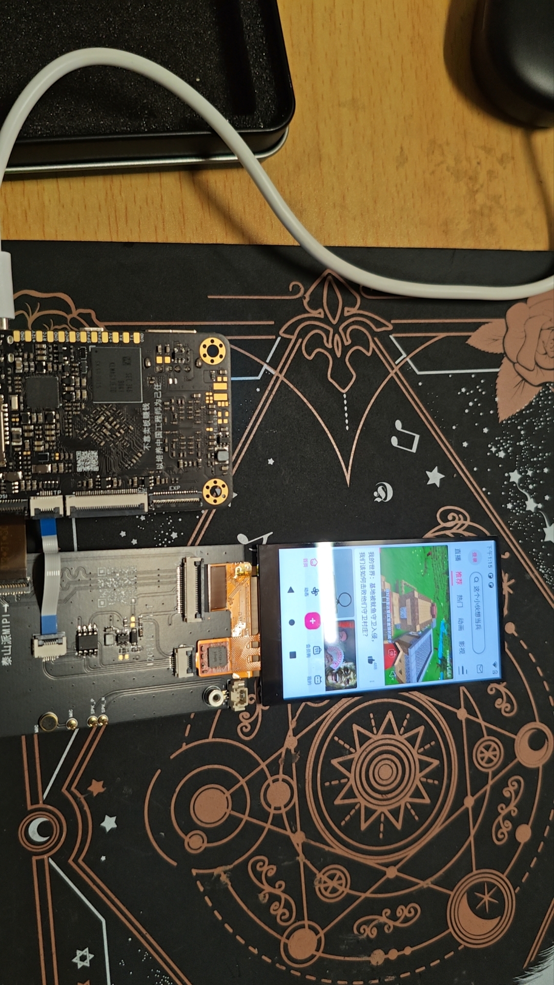
Here's a summary of some problems I encountered while tapping the screen.
The first one was compiling Android. My computer only has 16GB of RAM, and even less can be allocated to the virtual machine. Normally, it shouldn't be able to compile, but I joined a training camp group and learned a few tricks from the experts.
root@lckfb:/home/lckfb_tspi/android11/Release/tspi_android_sdk_20230909# cd u-boot && ./make.sh rk3566 && cd ../kernel && make clean && make distclean && make ARCH=arm64 tspi_defconfig rk356x_evb.config android-11.config && make ARCH=arm64 tspi-rk3566-user-v10.img -j16 && cd .. && source build/envsetup.sh && lunch rk3566_tspi-userdebug && make installclean -j16 && make -j16 && ./mkimage.sh
When executing the above commands for a full compilation, change the three j16s to j4. The gist is that the original 16-thread compilation was reduced to 4 threads, which alleviated the memory shortage to some extent. However, errors still occurred later. At this point, changing j4 to j1 usually resulted in successful compilation, but it was much slower. Of course, you could use j1 initially, but it would still be very slow. You can increase the value initially, then decrease it when errors occur. On the second run, be sure to remove `make clean && make distclean` from the compilation commands; otherwise, the results of the first compilation will be erased, rendering the effort wasted.
Secondly, when flashing the kernel alone, I spent an entire afternoon flashing it, repeatedly watching the video and changing the device tree, but the screen wouldn't light up.
Later, I discovered the file path was incorrect. The fully compiled result flashing path was `ockdevImage-rk3566_tspi` , while the single-kernel flashing path was
different. This small kernel issue took me an entire afternoon to figure out QAQ. Another issue was that the flashed Android system would show ERR_UNKNOWN_URL_SCHEME errors when searching web pages. This is because it only supports HTTP and HTTPS protocols by default. Other protocols require modifying a file (which I couldn't find). The final solution was to use adb to directly install a browser, and then it worked. I gained a lot from following the training camp. First, I gained a basic understanding of embedded Linux, and second, I gained a rudimentary understanding of device trees. I hope LCSC continues to thrive!
PDF_【LCSC Taishanpai Development Board】Android Mini Phone.zip
Altium_【LCSC Taishanpai Development Board】Android Mini Phone.zip
PADS_【LCSC Taishanpai Development Board】Android Mini Phone.zip
BOM_【LCSC Taishanpai Development Board】Android Mini Phone.xlsx
94484
electronic


 京公网安备 11010802033920号

 SHD2185B


