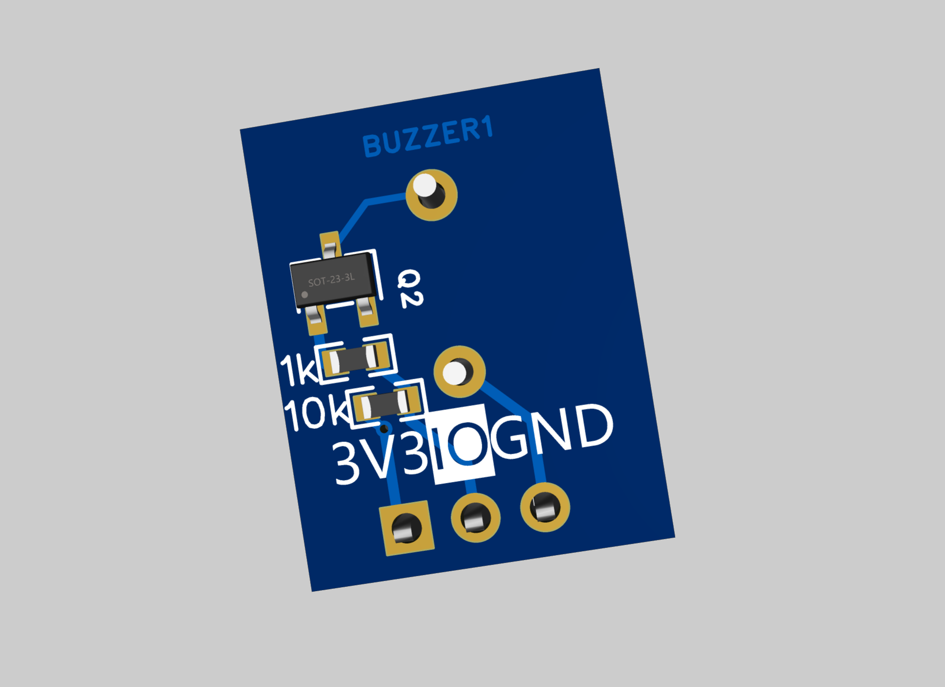
No need to buy a passive buzzer module, you can make one yourself.
The input is not polarity-sensitive, but the output is polarity-sensitive. The power supply to the relay is disconnected by pulling down the relay voltage.
The input is not polarity-sensitive, but the output is polarity-sensitive. The power supply to the relay is disconnected by pulling down the relay voltage.
I
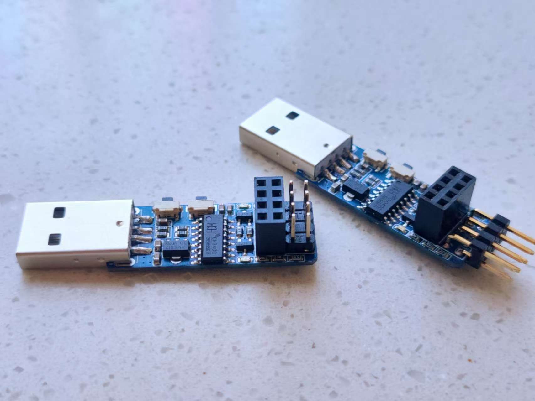
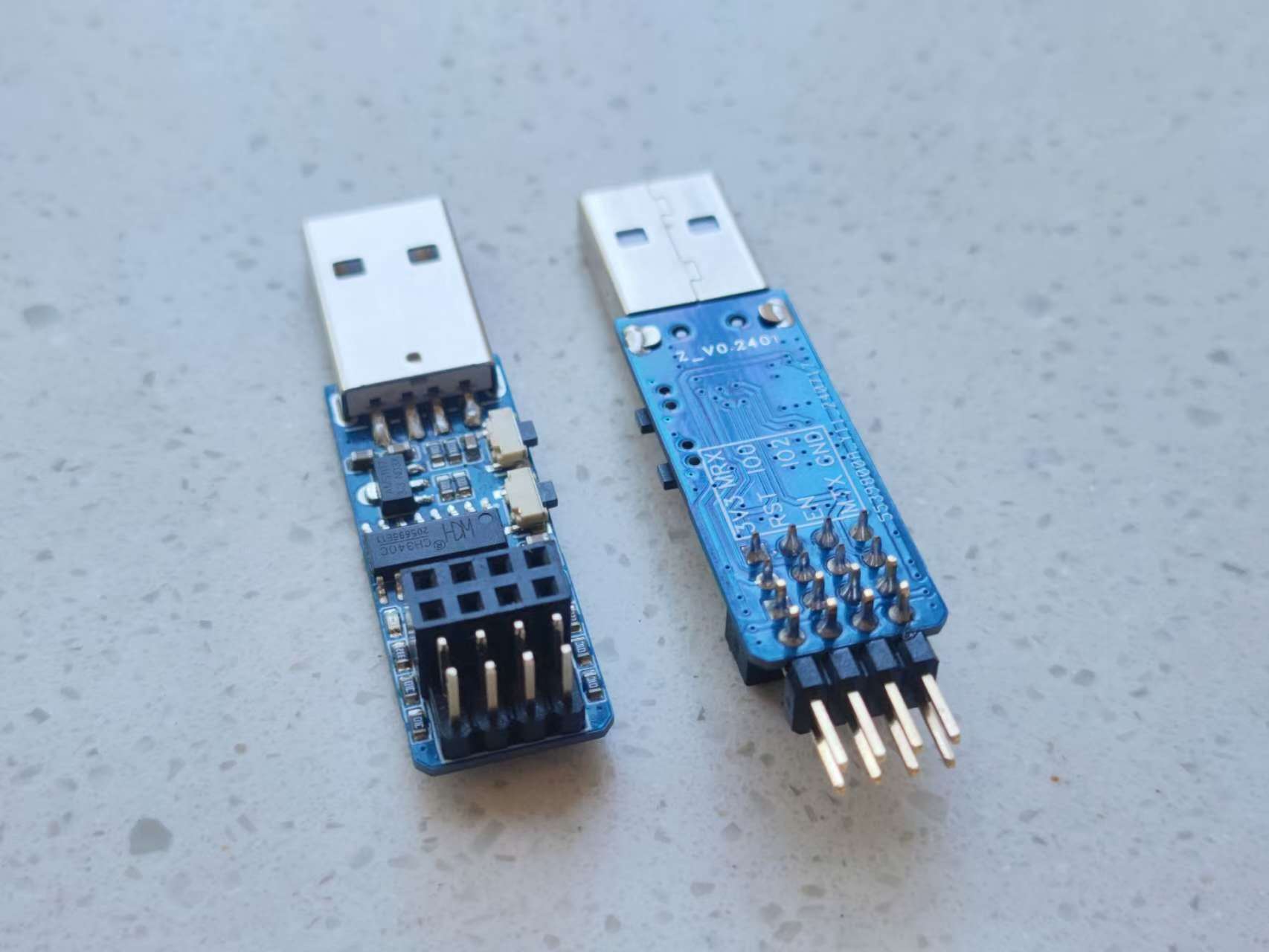
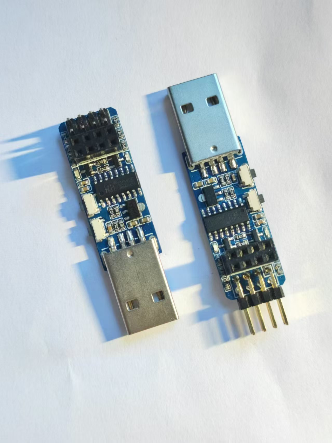
previously purchased several programmers claiming to be CH340C from a certain platform, each with an ESP01S module. None of them worked properly; the chip markings were worn off, and the circuitry differed from the CH340C's specifications. Frustrated and not wanting to waste the ESP01S, I designed this board myself.
This
project does not include the ESP01 module, only the programmer. Automatic ESP download is supported. The board uses a USB-A interface. The two buttons are: the one closer to the USB port is the RST button, and the other is a low-level IO0 button for ESP development. The 2x4 header can be directly plugged into for ESP01 module development. The 2x4 header pins have the same pin arrangement as the header, corresponding one-to-one, and are used for external DuPont wires to program the microcontroller. For ease of understanding, MRX directly corresponds to the microcontroller's RXD pin, and MTX directly corresponds to the microcontroller's TXD pin; no swapping is required. The Windows Device Manager
was verified
to correctly recognize the serial port. The ESP01S module was successfully programmed using the official ESP programming program. After programming with MicroPython, the MicroPython development tool recognized the module correctly and could also program the microcontroller successfully. (
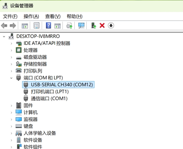
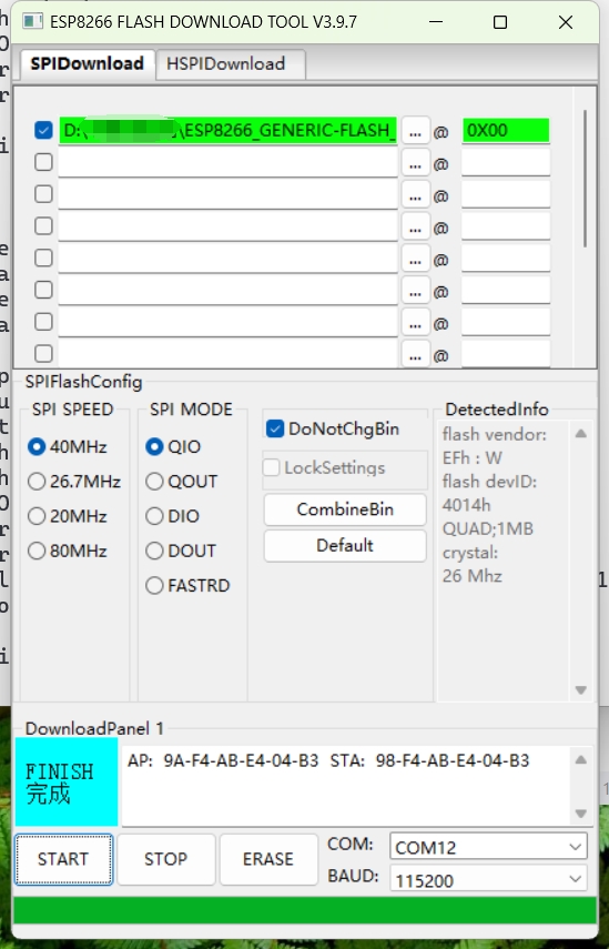
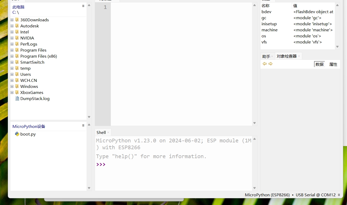

Image of the actual device follows.)
PDF_CH340C Burner.zip
Altium_CH340C programmer.zip
PADS_CH340C programmer.zip
BOM_CH340C programmer.xlsx
93145
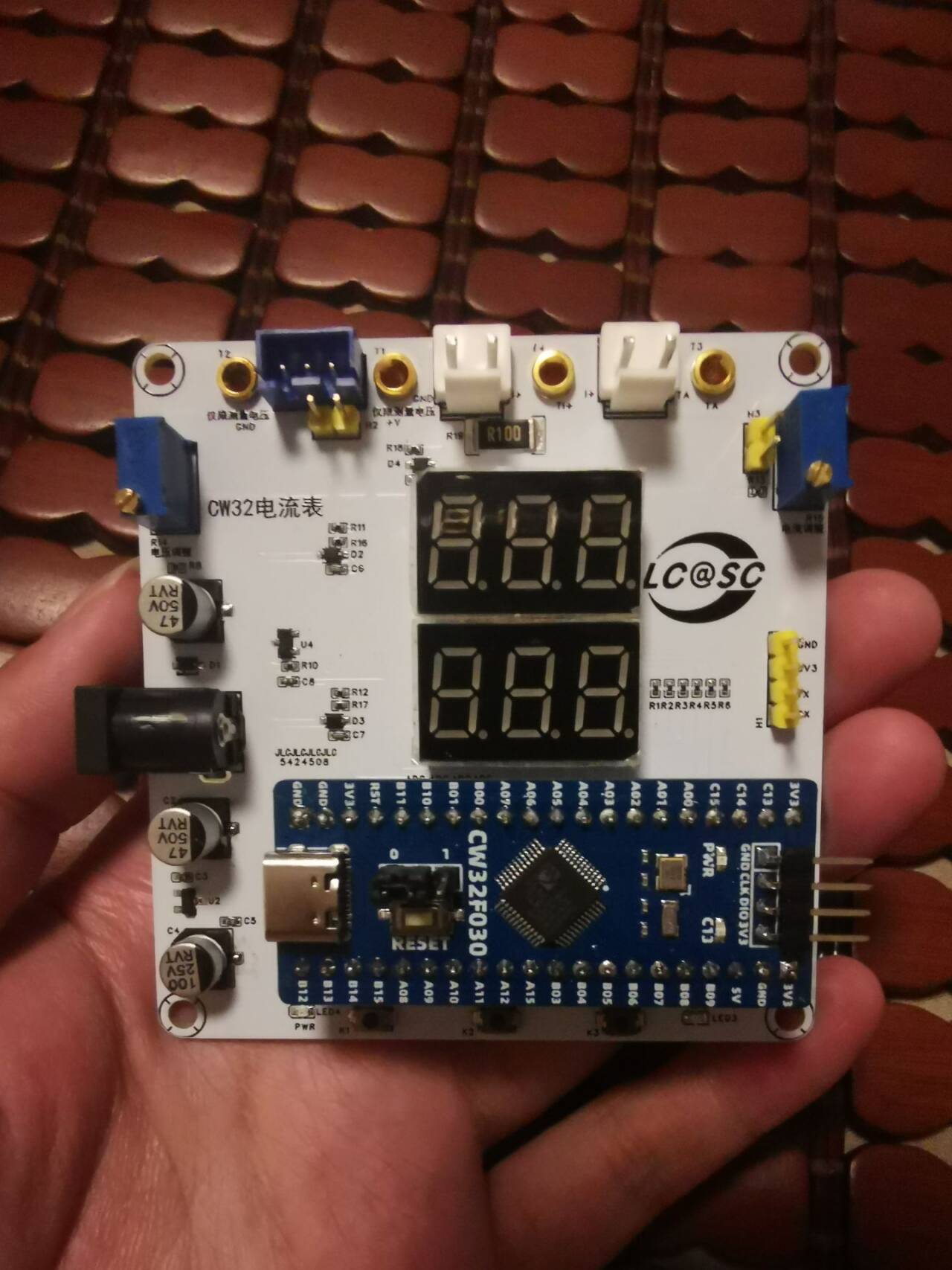
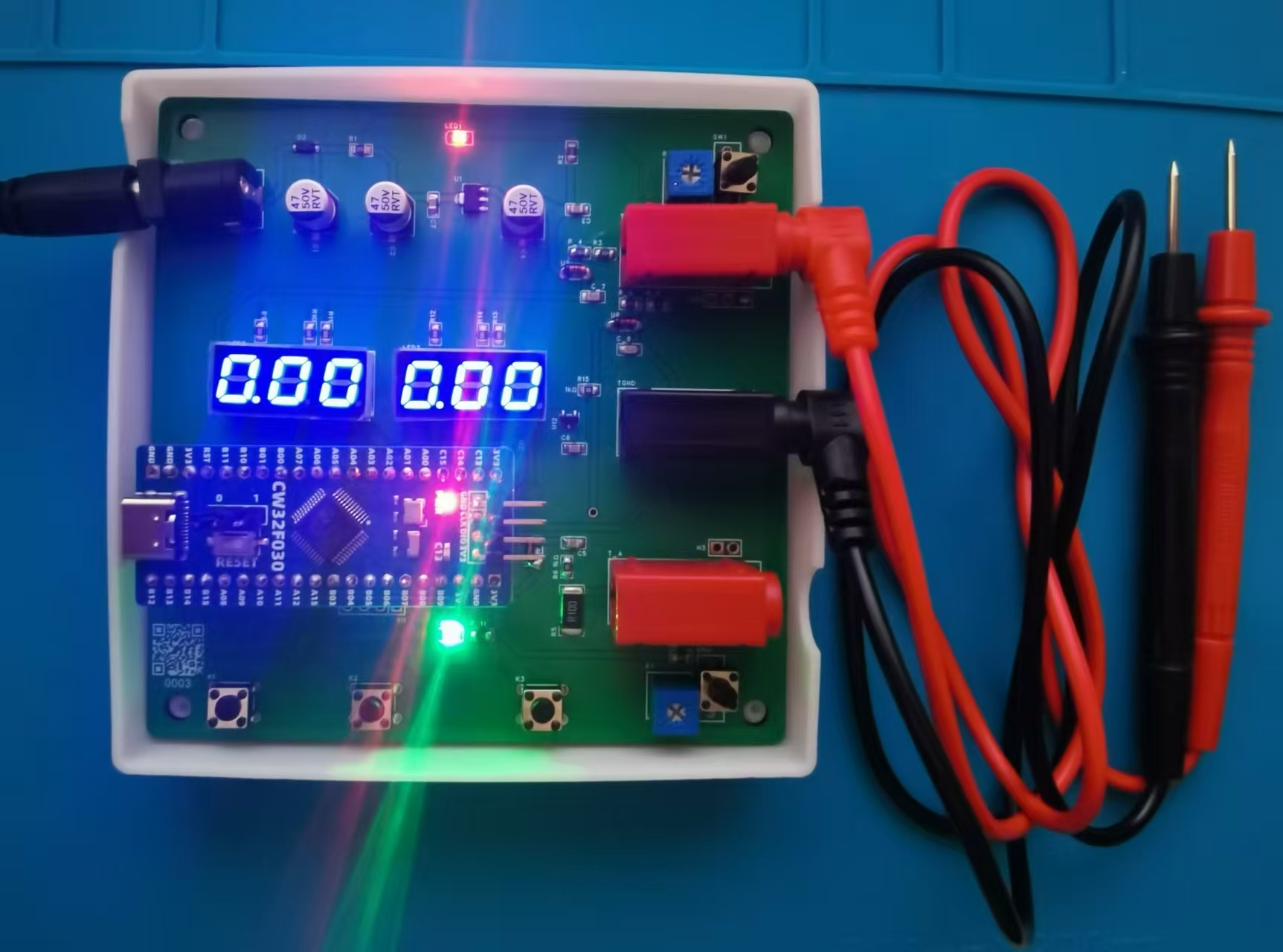
CW32 Voltage and Current Meter
Based on the CW32F030C8T6 geospatial voltage and current meter, this training camp taught me about CW32 development, ADC usage, and current sampling.
Participating in this training camp was beneficial because the strict rules required the use of development boards, so I had to obediently settle down and immerse myself in learning. This allowed me to fortunately discover the high precision and high configuration of the CW32 ADC. A powerful current and voltage meter can be implemented with just an MCU, without op-amps or current sensing devices like the INA226. Thanks to Engineer Li for the detailed and informative tutorials, and thanks to LCSC EDA for providing this excellent learning opportunity.
The learning content was quite extensive, so to avoid interference, I didn't make many changes; it was basically a direct copy of the instructor's work. To reduce the purchase of consumables, I made full use of the surface-mount components I had on hand. Resistors, capacitors, and LEDs were all replaced with surface-mount components, resulting in a smaller overall size. I made a mistake with the digital display; it's a bit too large.
This current and voltage meter benefits from the CW32's 12-bit precision ADC, using a successive approximation method to measure relatively accurate voltage values. A 12-bit ADC means 2 to the power of 12, or 4096 voltage data levels. From 0 to 4096 corresponds to a range of 0 to 1.5V. The 1.5V is the MCU's internal reference voltage (an additional 2.5V reference voltage is also available, but lower voltages generally offer higher accuracy). For comparison, testing, and calibration, the board also provides a TL431 voltage reference chip, offering a 2.5V reference voltage with relatively high accuracy. Current measurement is also done by measuring the voltage and calculating the current value using a 100mΩ current sensing resistor. The 100mΩ current sensing resistor was
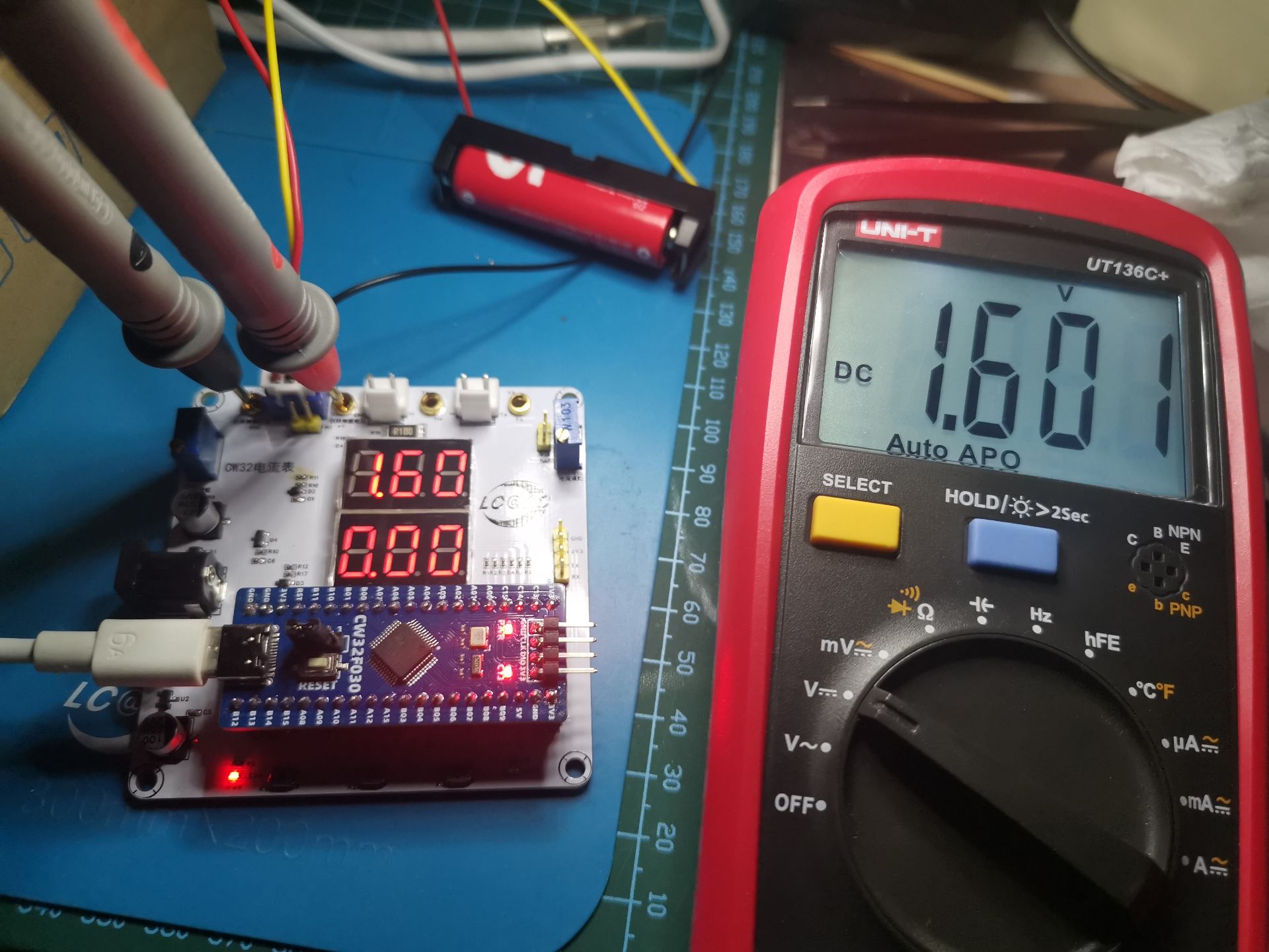
used for current measurement. I followed the teacher's Kelvin connection method; I'm not sure how effective it is. The accuracy is acceptable. It's very accurate even without calibration! I measured a dry cell battery at 1.601V with a good multimeter, and this voltmeter and ammeter gave roughly the same reading.
Below is a picture of the actual device:
This training camp also encountered some difficulties, both in hardware and software. For example, I soldered the wrong voltage divider resistor, resulting in a 20-fold difference in the measured value. After a moment of confusion, I realized my mistake and immediately replaced the resistor to correct it.
In terms of software, I also had a period where compilation failed. I only understood the problem after comparing several experimental examples.
This training camp... Mr. Li, the instructor for CW32, provided meticulous explanations. Although the schematic diagram was a bit rough at first (there were a few discarded networks, I didn't know how to draw the 2mm banana plug, (A) in the diagram is an ammeter diagram, etc., which Mr. Li assumed everyone should know), after a few days of learning, I found that Mr. Li's video courses were full of valuable information. He even specially extracted common mistakes made by students and provided targeted explanations. I really learned a lot.
CW32 voltage and current meter.zip
QQ Video 20240813121010.mp4
PDF_CW32 Voltage and Current Meter.zip
Altium_CW32 voltage and current meter.zip
PADS_CW32 Voltage and Current Meter.zip
BOM_CW32 Voltage and Current Meter.xlsx
93146
Warm Winter Thermometer
The DS18B20 is a commonly used high-precision single-bus digital temperature measurement chip. It features small size, low hardware overhead, strong anti-interference capability, and high accuracy. Today, we will use the DS18B20 to design a lightweight electronic thermometer.
The DS18B20 is a commonly used high-precision single-bus digital temperature measurement chip. It features small size, low hardware overhead, strong anti-interference capability, and high accuracy.
Specifications: Temperature measurement range -55℃ to +125℃, with an error of ±0.4°C within the range of -10℃ to +85℃.
It returns a 16-bit binary temperature value
. Master-slave communication uses a single bus, meaning data transmission and reception are done via a single wire.
No external components are required; the chip itself can function independently.
The DS18B20 includes an internal EEPROM, and the digital conversion accuracy and alarm temperature can be set via configuration registers. Even after a power outage, it retains the resolution and alarm temperature settings.
Each DS18B20 has a unique 64-bit ID, allowing any number of DS18B20s to be connected to a single bus. The temperature value is read from the ROM by searching the DS18B20. The DS18B20 returns a 16-bit binary number representing the detected temperature, with the high five bits indicating whether it's positive
or
negative. If all five high bits are 1, the returned temperature is negative; if all five are 0, the returned temperature is positive. The following 11 bits represent the absolute temperature value. Converting this to decimal and multiplying by 0.0625 gives the current temperature value.
The DS18B20 has three pins:
GND: Power ground; DQ: Digital signal input/output; VDD: External power supply input. The operation of the DS18B20 can be divided into three steps:
1. Initialize the DS18B20; 2. Execute ROM instructions; 3. Execute DS18B20 function instructions
. The second step, executing ROM instructions, involves accessing each DS18B20, searching for its 64-bit serial number, reading the matching serial number value, and then matching it with the corresponding DS18B20. If we are only using a single DS18B20, we can skip the ROM instructions. The byte for skipping ROM instructions is 0xCC.
Here, we use a 74HC573, a 51 microcontroller minimum system, and a DS18B20.
The simulation is as follows:


PDF_WinterWarmThermometer.zip
Altium_WinterWarmThermometer.zip
PADS_Warm Winter Thermometer.zip
BOM_Winter Warmth Thermometer.xlsx
93149
GL3224 Card Reader
Affordable and good-looking GL3224 card reader
Main controller: The GL3224
, including the chip and resistors, costs less than ten yuan, which is much cheaper than card readers on Taobao.

Read/write speed test:

There was a problem with the firmware update; anyone knowledgeable can offer some guidance.

PDF_GL3224 Card Reader.zip
Altium_GL3224 card reader.zip
PADS_GL3224 card reader.zip
BOM_GL3224 card reader.xlsx
93150
electronic

 The casing for the voltage and current meters is also designed, as shown below:


 京公网安备 11010802033920号

 1200RGF15IP23HA


