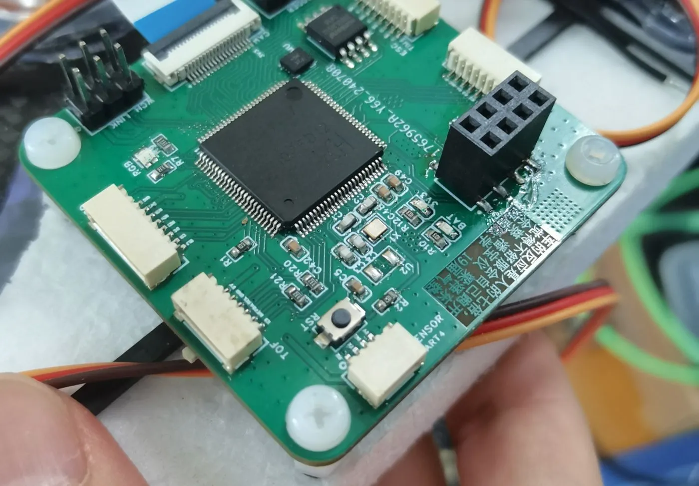
I. Onboard Peripherals:
1. CH32V307 main control chip;
2. HSE (16MHz) and LSE (32.768kHz) crystal oscillators;
3. W25Q32 (using SPI interface);
4. BMI270 (Zhufei's trade name is IMU660RA);
5. Tri-color LED;
6. Toggle switch;
II. Onboard Interfaces
: 1. WCH-link interface, including one serial port (UART3);
2. DVP interface (Zhufei's main drilling camera interface, using a flat cable for connection, with independent 3.3V voltage regulation);
3. SPI interface (with independent 3.3V voltage regulation, can be used for external screens);
4. I2C interface;
5. Wireless module interface (supports Zhufei's wireless serial port);
6. Sensor interface (serial port, can be used for external sensor boards);
7. Encoder interface;
8. Servo ESC interface (12 timer channels);
9. Power Supply Voltage Measurement Interface;
III. Design Concept
This board is designed for the 19th Intelligent Vehicle Air Cushion Group. The design considers a fully brushless solution, powering the hull with 6 M1106 brushless motors and 4 MG90D servos. Thrust vector control is achieved using servos and brushless motors. Therefore, the board has as many as 12 PWM channels, but almost no GPIOs or conventional brushed driver interfaces.
Early designs considered using a differential pressure sensor to create a custom pitot tube for speed measurement. This resulted in a seemingly meaningless sensor interface on the board for connecting a custom speed measuring board. However, due to system complexity, the pitot tube solution was abandoned. Therefore, in version 4.2 and later, an encoder interface was temporarily added to the motherboard, using a speed measuring wheel for speed measurement.
To facilitate wiring, the peripherals and pins used by various sensors in the Zhuifei library were significantly modified during the board design. Therefore, modifications to the peripherals used by the corresponding sensors in the Zhuifei library are necessary.
IV. Defect
1. Due to the excessive pursuit of size in the early stage, a 2016 crystal oscillator was used. However, since the common resistance value of the 2016 crystal oscillator does not include 8MHz, a 16MHz frequency was used. This means that whether using the ZF library or the standard library, the crystal oscillator frequency needs to be modified in the clock configuration file. The process is as follows:
(1) Modify the HSE_VALUE definition in the ch32v30x.h header file to ((uint32_t)16000000) to adapt to the 16MHz crystal oscillator;
(2) Modify the clock_set_freq() function in zf_common_clock.c, and add the RCC_PLLXTPRE_HSE_Div2 macro definition in the PLL configuration part (lines 108-125) to divide the input clock signal.
Using the official standard library, only step (1) is required. Using the ZF library, steps (1) and (2) need to be executed.
If you do not want to execute the above process, you need to modify the crystal oscillator package and modify the layout of the relevant parts.
2. With only one switch, it is difficult to switch between multiple modes, and it is almost impossible to achieve offline parameter tuning.


 京公网安备 11010802033920号

 78D08LG-TNA


