I. Function Introduction 1. Voice control for curtain opening/closing and mode switching 2. Infrared remote control 3. Raindrop sensor controls curtain opening/closing 4. Light sensor controls curtain opening/closing (priority lower than raindrop sensor) II. Schematic Diagram
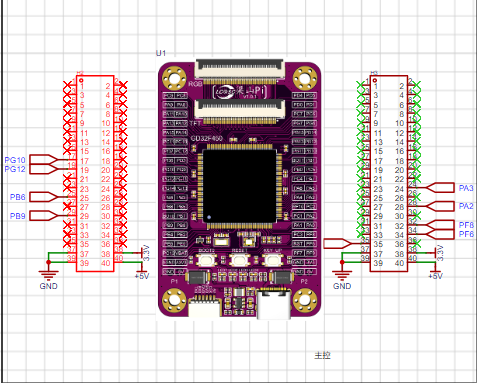
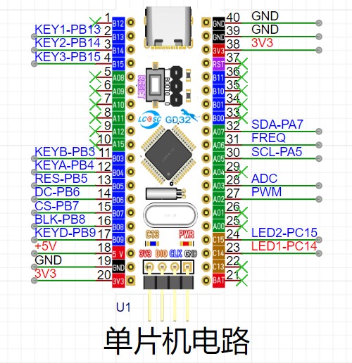
1. Main control circuit – Liangshanpai development board
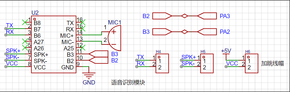
2. Voice recognition – Implemented using Hailingke's HLK-V20 module
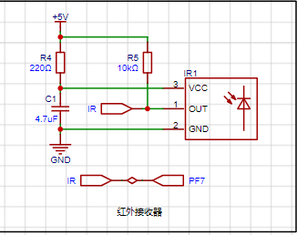
3. Infrared reception – Infrared remote control achieved through IRM-56384 infrared receiver
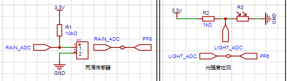
4. Raindrop detection and light intensity detection
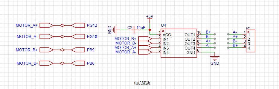
5. Curtain opening/closing control – Motor drive control implemented using LV8548MC
Lark 20240812-164628.mp4
PDF_Smart Curtains.zip
Altium Smart Curtains.zip
PADS_Smart Curtains.zip
BOM_Smart Curtains.xlsx
93183
LM317 current amplification 6.5A
LM317 current amplification circuit
The initial design of this power supply was driven by the fact that many buck converters sold online either have too small an input voltage range or too small an output current, making them unable to power multiple modules or servos. Fortunately, I had the LM317 chip on hand, which supports a relatively wide input voltage range of 1.2-37V and an output current of 1.5A. Combined with the Darlington transistor TIP127 for current amplification, it can theoretically output 6.5A of current. Finally, I no longer worry about it not being able to power the servos. Adjusting the potentiometer changes the output voltage of ADJ. If a larger current is needed, two Darlington transistors can be connected in parallel. For high current, heatsinks should be added to the transistors. Ripple rejection ratio is 10dB-14dB.
VIN: 1.2-37V
VOUT: 3V/ADJ
PDF_lm317 Amplification 6.5A.zip
Altium_lm317 Amplification 6.5A.zip
PADS_lm317 Amplify Current 6.5A.zip
BOM_lm317 Amplification 6.5A.xlsx
93186
Microcontroller Innovation Competition - Core Board
STC 32-bit microcontroller core board, designed by JLCPCB EDA Professional Edition, is easy for beginners to learn and has a simple design.
The controller is a 32-bit 8051 core microcontroller: STC32G12K128, with an onboard CH340 chip, a reserved LED, a button, and an external 24C02 memory.
Flexible design: all function pins are exposed for easy verification
and debugging of various functions. Convenient: an onboard CH340N serial port chip allows for program downloading and debugging without a programmer. This course aims
to help you master microcontroller circuit design and program development skills, and learn project development.
PDF_Microcontroller Creative Competition - Core Board.zip
Altium Microcontroller Creative Competition - Core Board.zip
PADS_Microcontroller Creative Competition - Core Board.zip
BOM_Microcontroller Creative Competition - Core Board.xlsx
93187
#JALCIC Training Camp# [1712472A] #Simple Digital Oscilloscope
The 2024 LCSC Training Camp Project [Beginner Zone] uses GigaDevice's GD32E230C8T6 domestic microcontroller as the core board. Based on the official version, some components have been modified. Most of the components are pluggable, and some are surface-mount components, making it easy to replicate and get started.
I. System Board Selection:
The main control board used is the LCSC GD32e230c8t6 minimum system board. I bought two, one of which was a free gift with a coupon. At the time, boards were in short supply, so I didn't rush to replicate the project. I waited for the official development board release, partly because I hadn't used GigaDevice chips before and wanted to try them out.
II. Main Circuits:
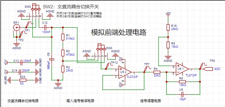
1. Analog Front-End Processing Circuit:
The analog front-end processing circuit includes both DC and AC coupling modes, switched via switch SW2. In DC coupling, a 100nF capacitor blocks the DC component.
Switch SW3 selects whether to attenuate the input signal; the attenuation circuit uses a resistor divider to reduce the voltage to 1/50 of the original signal.
The two operational amplifiers, TL072IP, act as a voltage follower and a proportional amplifier, respectively. The input signal first passes through the voltage follower, utilizing its high input impedance and low output impedance for impedance matching, before being converted by the proportional amplifier. The proportional amplifier circuit outputs Vo = (5 − Vin) / 2. The voltage range of the ADC acquired by the microcontroller is 0~3.3V. With 1/50 attenuation, the measurement range is approximately -80V~250V; without attenuation, the measurement range is approximately -1.6V~5V.
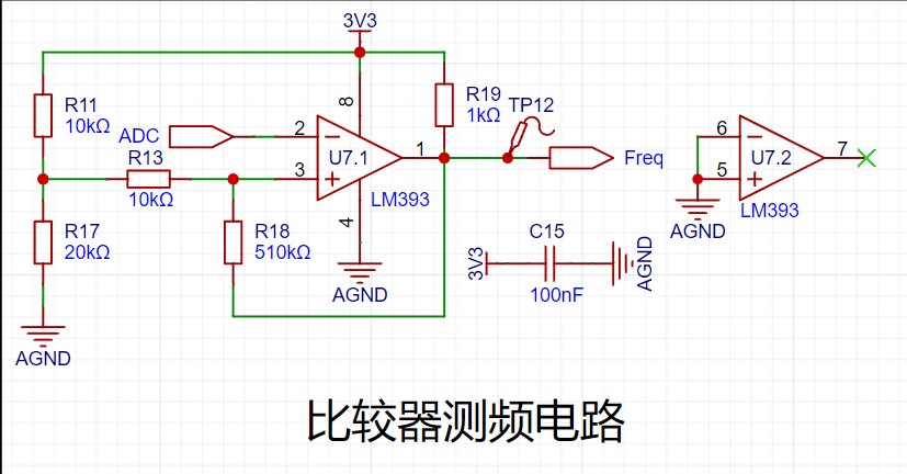
2. Comparator frequency measurement circuit:
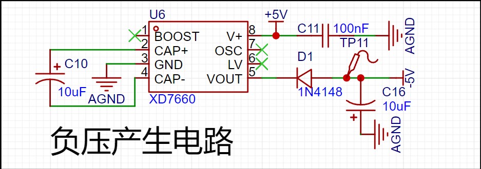
3. Negative voltage generation circuit
: This circuit generates a -5V voltage to provide a -5V voltage to the analog front-end processing circuit.
III. Other circuits:
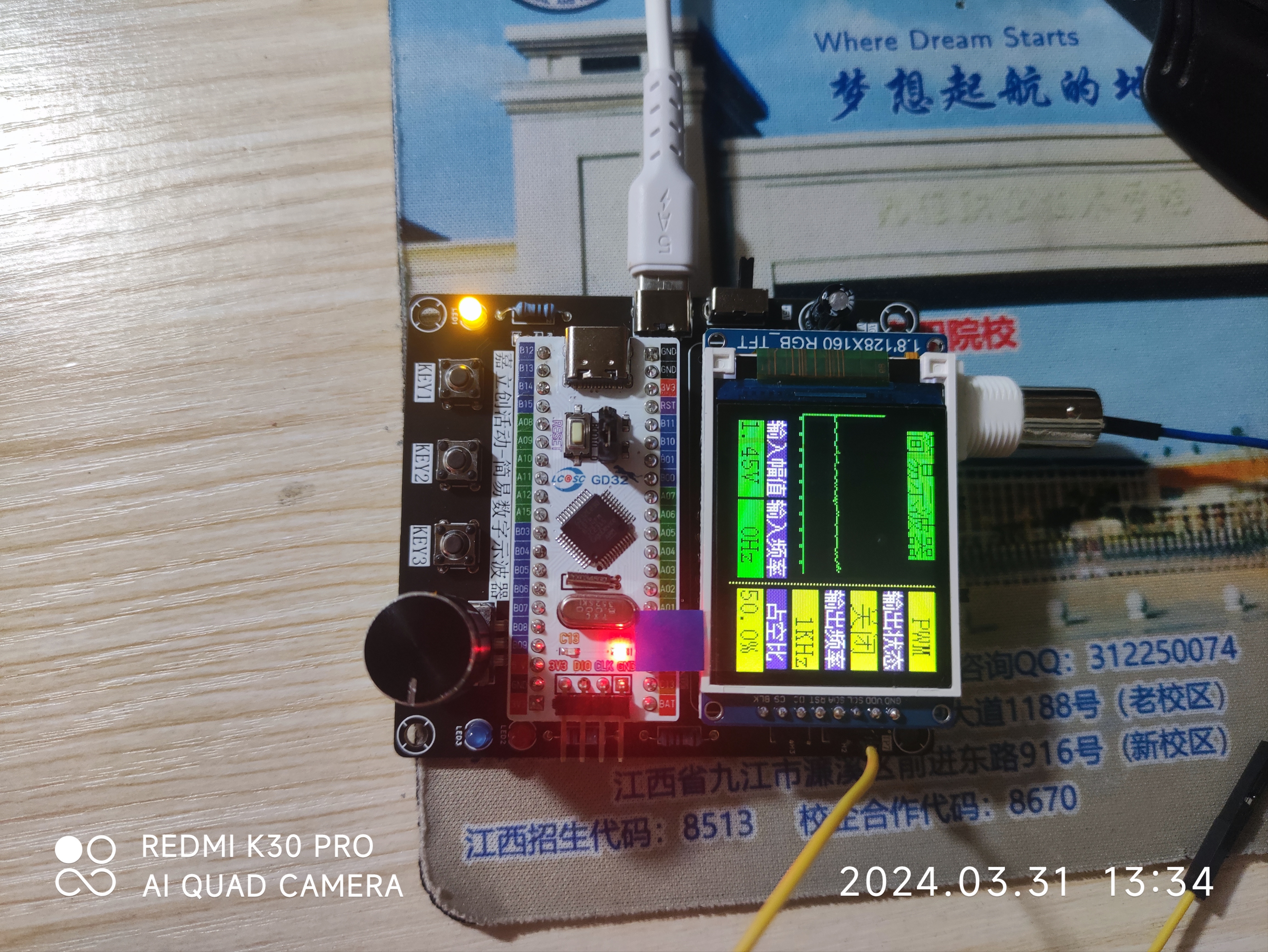
The USB power input circuit provides voltage and current to the entire circuit; a 1.8-inch TFT screen, with an ST7735 main controller, uses SPI communication to display waveforms and some oscilloscope parameters; a rotary encoder controls waveform scaling and pause; three buttons are used for PWM output frequency adjustment, duty cycle adjustment, and PWM generation switch, respectively.
IV. Finished Product Display
Oscilloscope.7z
PDF_#JALCIC Training Camp#【1712472A】#Simple Digital Oscilloscope.zip
Altium_#JALCIC Training Camp#【1712472A】#Simple Digital Oscilloscope.zip
PADS_#JALCIC Training Camp#【1712472A】#Simple Digital Oscilloscope.zip
BOM_#JALCIC Training Camp#【1712472A】#Simple Digital Oscilloscope.xlsx
93188
#Training Camp# Simple Oscilloscope_Replica
Replicating the 2024 Oscilloscope Bootcamp Project
Learning to design and build a digital oscilloscope is highly beneficial for developing comprehensive abilities. This digital oscilloscope project includes the design and development of microcontroller circuits, calculations for signal conditioning circuits, design of human-computer interaction, and design of the enclosure model. It integrates knowledge of analog circuits, microcontroller design, circuit and PCB design, and enclosure design. Considering the learning pace of beginners, this introductory digital oscilloscope project is specifically designed for this purpose, suitable for introductory electronics training and microcontroller learning. For detailed project information, please refer to the official documentation 202: Simple Digital Oscilloscope Project Document (yuque.com).
7606b968db5e2f0310d24803d41f3e9a.mp4
PDF_#Training Camp# Simple Oscilloscope_Replica.zip
Altium_#Training Camp# Simple Oscilloscope_Replica.zip
PADS_#Training Camp# Simple Oscilloscope_Replica.zip
BOM_#Training Camp#Simple Oscilloscope_Replica.xlsx
93190
Voltmeter and Ammeter Replica
Voltage and current meters based on the LCSC Diwenxing development board.
This voltmeter and ammeter can measure voltage from 0-30V and current from 0-3A. The measurement range can be increased by changing the resistor, with an accuracy of ±1%. A calibration function is provided within the 5V-9V and 0.5A-1A range, and the calibration range can be further expanded. Five modes are available, switched using the buttons on the left. Mode zero displays the voltage and current normally. Mode one calibrates to 5V, mode two to 9V, mode three to 0.5A, and mode four to 1A. Calibration confirmation is done using the middle button. The rightmost button returns to mode zero.
Voltmeter and Ammeter Demonstration.MP4
Voltmeter and Ammeter Demonstration.mp4
PDF_Voltage and Ammeter Replica.zip
Altium voltmeter/ammeter replica.zip
PADS_Voltage and Ammeter Replica.zip
BOM_Replica Voltmeter and Ammeter.xlsx
93191
#9th LCSC Electronics Design Contest# ESP32-S3 Low-Power E-ink Indoor Air Quality Monitor
Implement an ultra-low power e-ink screen air quality monitor driven by ESP32, using Sensory's SHT40 and SGP30 as the main sensors.
1. Project Function Introduction:
This competition required the creation of a temperature and humidity (SHT40 sensor) detector. The official version uses a digital tube display. I thought I could add an e-ink screen to create a low-power detector. Since I was using an e-ink screen, I decided to replace the MCU with an ESP32 and add an SGP30 air quality sensor. This was the main idea behind the project.
2. Hardware:
There are many versions of the ESP32. Initially, I considered the ESP32-PICO-V3. The main reason was that it's a SIP (System-in-Package), requiring minimal external circuitry. Compared to the ESP32 or ESP32-S series chips, the ESP32-PICO-V3 integrates a crystal oscillator, power supply, and other basic peripheral circuitry. Although the official reference circuit for the ESP32-PICO-V3 includes a power supply filter capacitor, I felt that this chip could be used simply by powering it on and adding an antenna. Ultimately, I didn't choose it for the final product; the reason was simply its high price.
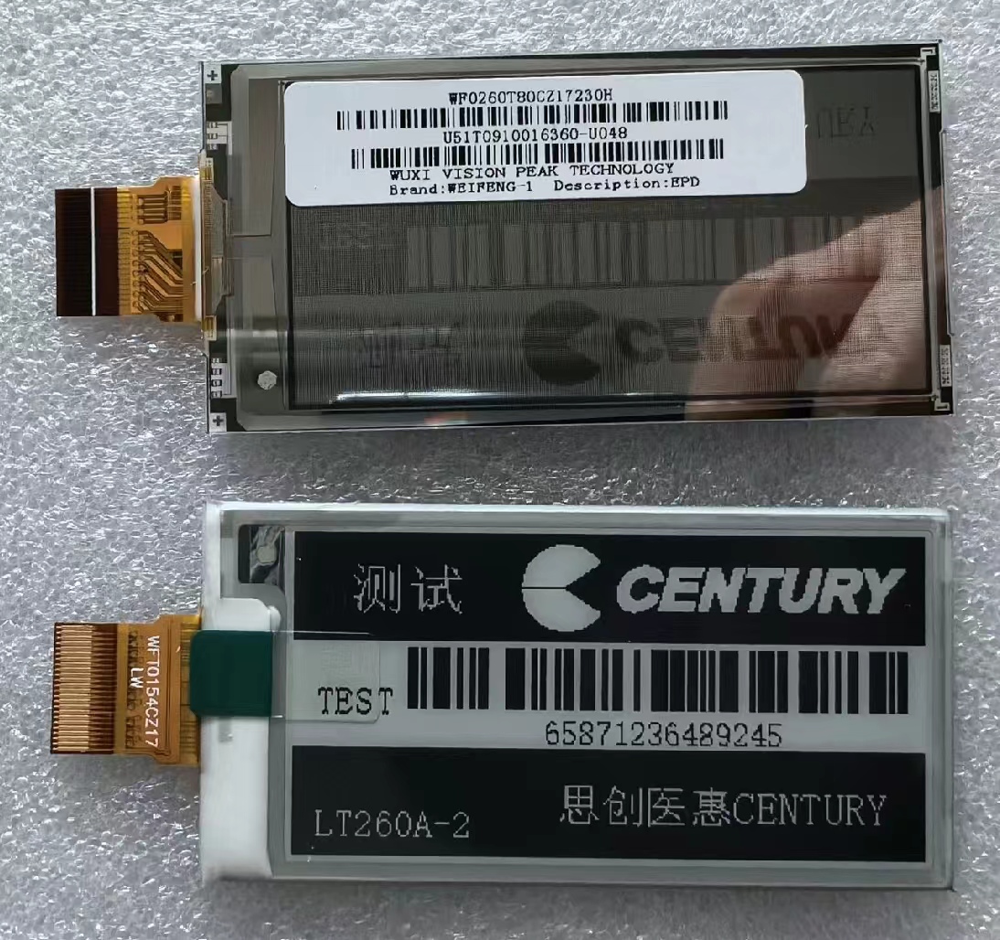
I purchased a 2.66-inch black and white e-ink screen on Xianyu (a second-hand marketplace). The seller said it was compatible with the GDEW026T0D from Jiaxian, so driver issues shouldn't be a problem.
The first version used the ESP32-C3; although it has more peripheral circuitry, the chip is cheap enough. Below is the circuit diagram and PCB of the first version.
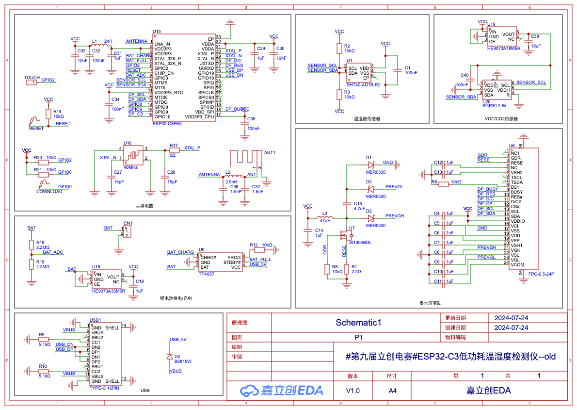
After soldering, the board couldn't recognize the chip. A careful check ruled out poor soldering and a faulty USB signal line. Due to a lack of tools, I couldn't check if the crystal oscillator and chip were working properly, so I had to abandon this solution.

The second version is the final product. This version directly replaced the ESP32-C3 chip with an ESP32-S3 module to improve the success rate. After soldering the board, the chip was easily recognized, and the sensor could be read. OK, next is writing the program.

A special note about soldering:
because the Shengshirui sensor is very small, especially the SHT40 which is a 1.5mm x 1.5mm DFN, solder flux got into the sensor's small holes during the first soldering. Although I cleaned it with alcohol, later when reading temperature and humidity, these values were consistently around 40, which is obviously incorrect. I replaced the SHT40 with a new one, and used a hot air gun to heat it during soldering, applying only a tiny amount of solder flux to avoid getting it into the holes. However, I noticed the temperature was still 4-5 degrees Celsius higher than normal, and I don't know why. Also, the SGP30 air sensor has a white protective film (not removed in the picture above), which allows for easy soldering and cleaning; just remember to remove it afterwards, otherwise the TVOC will remain at 400, meaning it won't detect any volatile organic compounds in the environment.
3. Software
Development: There are several ways to develop with the ESP32. The first way is to use the official ESP-IDF package directly. This involves installing an SDK and using your preferred editor to write code, or you can use PlatformIO in VS Code. The second way is with Arduino. Install the official espressif package on the Arduino and select an ESP32-S3 board with the same Flash memory as your module. Other methods include MicroPython, ESPHome, etc. I used ESPHome for software development because writing code is simply writing configuration files; once the sensor, screen, buttons, and other peripherals are configured, it's very simple.
Installing ESPHome is very simple; a single command on a Mac is all it takes:
`pip install esphome python-magic-bin`.
Of course, being extremely lazy, I didn't even want to write the ESPHome configuration file from scratch, so I had LLM write one for me. Below is the first version of the program written by GPT-4o (the complete program is in the attachment "temp-detector-gpt4o.yaml"):

GPT-4o's program basically implements the functions I described, except it can't provide the e-ink screen driver, which is understandable since I didn't provide it with more detailed information about the e-ink screen. Aside from not needing an e-ink screen, there are no other major problems, but there are quite a few minor ones, such as the `board` configuration causing compilation errors.
These minor problems are easy to fix; I modified the version based on GPT-4o. The final program is in the attachment "temp-detector.yaml," and "temp-detector.bin" is the compiled firmware. Note that you need to modify the Wi-Fi configuration to the corresponding Wi-Fi name and password.

3.1
Initially, I wanted to use the Waveshare driver included in ESPHome, but none of the drivers for different screen sizes worked for my e-ink screen. After a day of troubleshooting, I finally got it working using the official GDEW026T0D driver from GAC Display.
Of course, the official GAC Display driver can't be directly used in ESPHome; it's not optimally compatible. Therefore, a porting process is necessary. There are two approaches: one is to directly modify the Waveshare driver within ESPHome, which is highly intrusive and not recommended; the other is to create a component of ESPHome from the GAC Display driver.
To quickly implement the functionality, I modified the Waveshare driver first and then created a component later. The specific repair method is as follows:
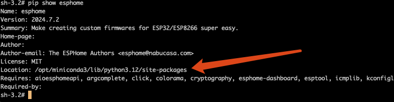
Use the command `pip show esphome` to find the ESPHome installation path. My installation path is /opt/miniconda3/lib/python3.12/site-packages.
Then, open the file /opt/miniconda3/lib/python3.12/site-packages/esphome/components/waveshare_epaper/waveshare_epaper.cpp in this path and modify it. I'm modifying the 2.70inv2 driver, which corresponds to the class WaveshareEPaper2P7InV2. Four functions need to be modified: first, modify get_width_internal and get_height_internal to the screen resolution; then modify the initialize function; and finally, modify the display function.

The modified waveshare_epaper.cpp file is attached.
3.2 Interface Design
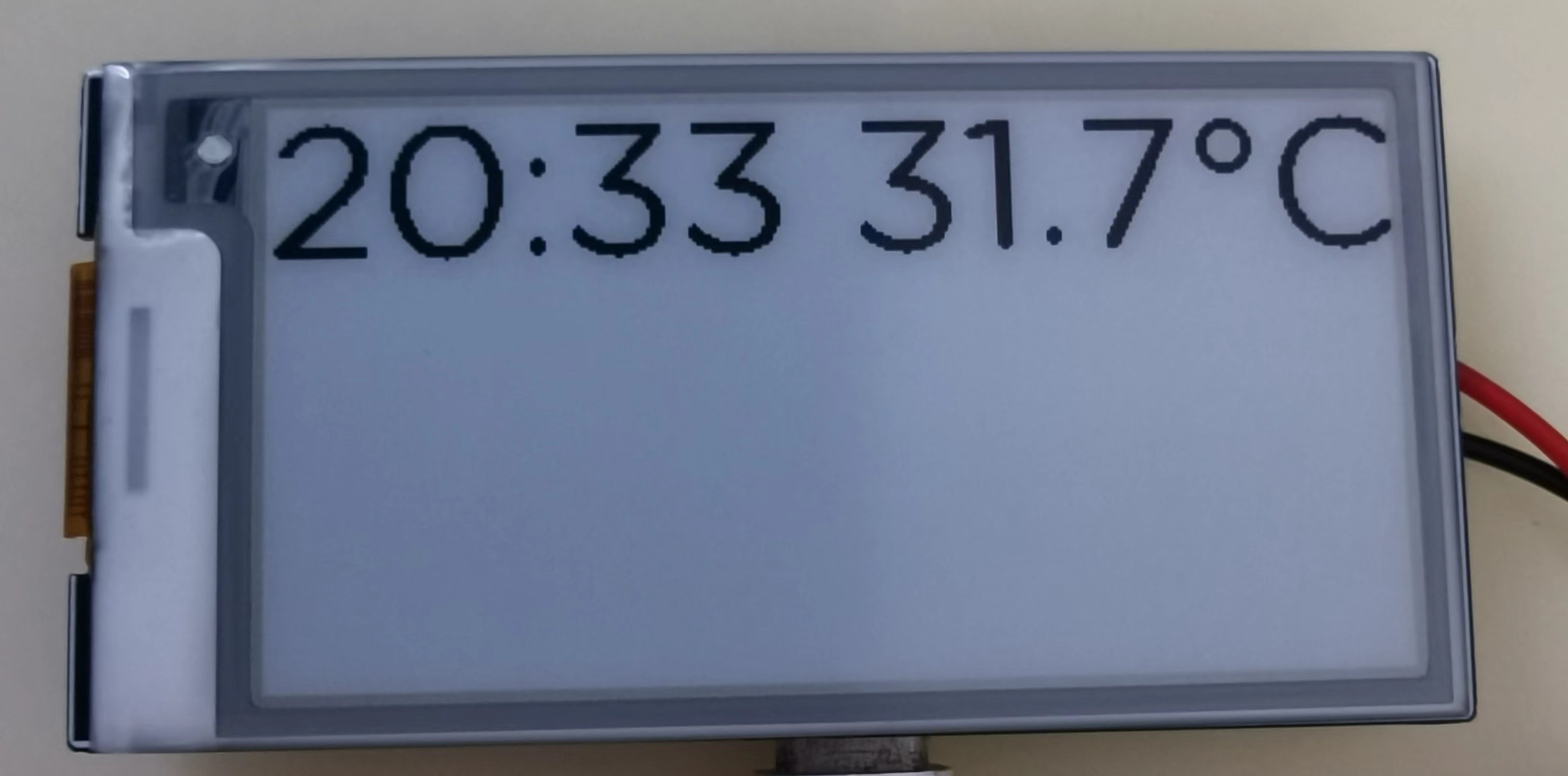
For the interface design of the e-ink screen, the first step is to find a suitable font. The following code uses the GothamRnd-Book.ttf font to display the text "20:33 31.7°C" at coordinates (0,0). The display effect is unsatisfactory; the text edges are not smooth, and the graininess is quite strong. The main reason is the low grayscale, and it is also related to the low DPI of the e-ink screen.

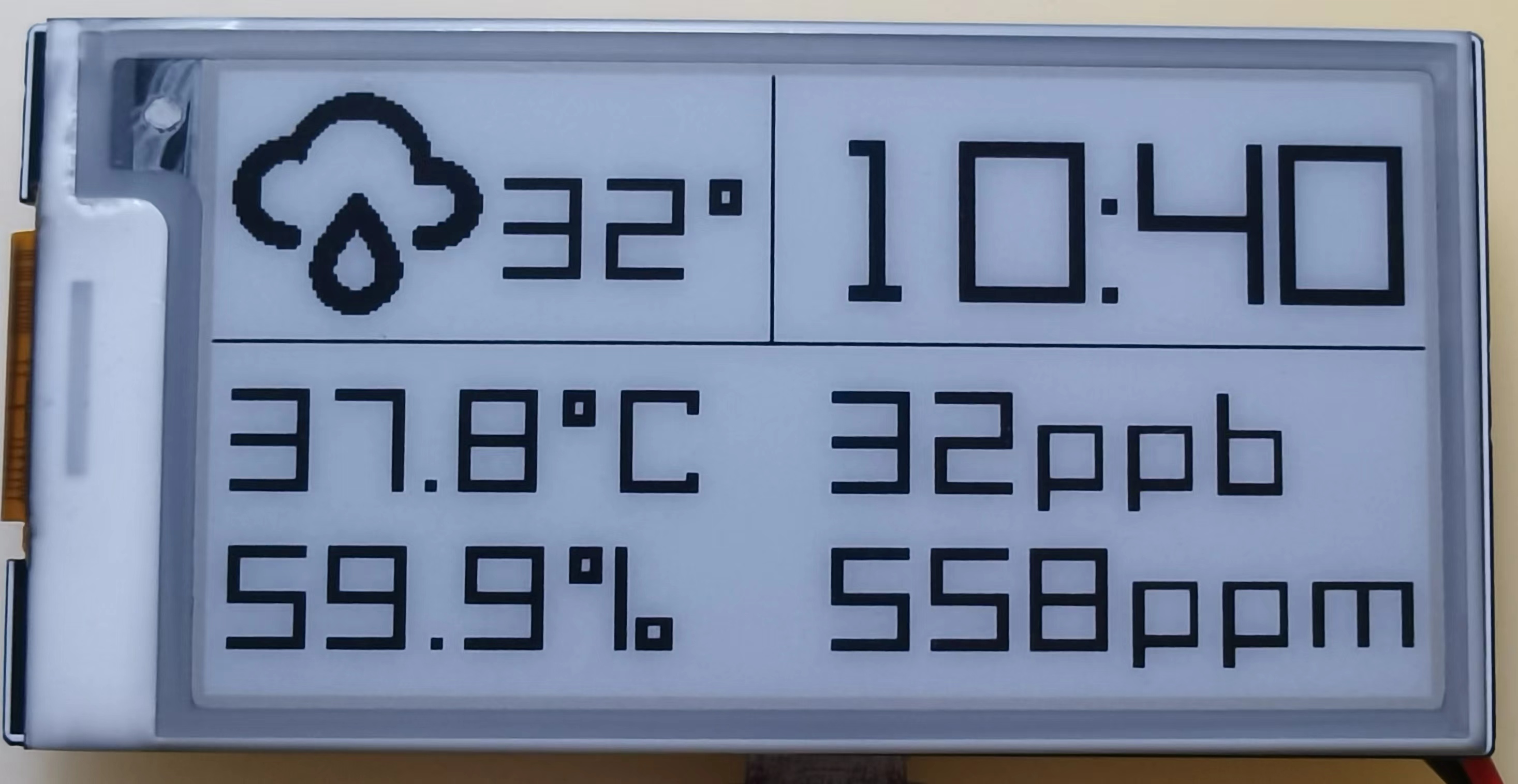
So what kind of font is suitable for display on an e-ink screen? Obviously, fonts without bevels and with straight lines should display very well. So I spent a morning looking at about 1,000 pixel-style fonts, and after testing about ten fonts, I chose the Acme-9-Regular font. The display effect is as follows:


The text display effect is much smoother and cleaner.
Note: I made an adjustment to the original Acme-9-Regular font, please see the appendix for details.
After selecting the font, the interface design became easier. I divided the screen into three areas: the upper left corner for weather information (this part is currently hardcoded and will be integrated with the weather interface later), the upper right corner for the time, and the bottom for the temperature, humidity, TVOC, and CO2 values. The code and effect are as follows:

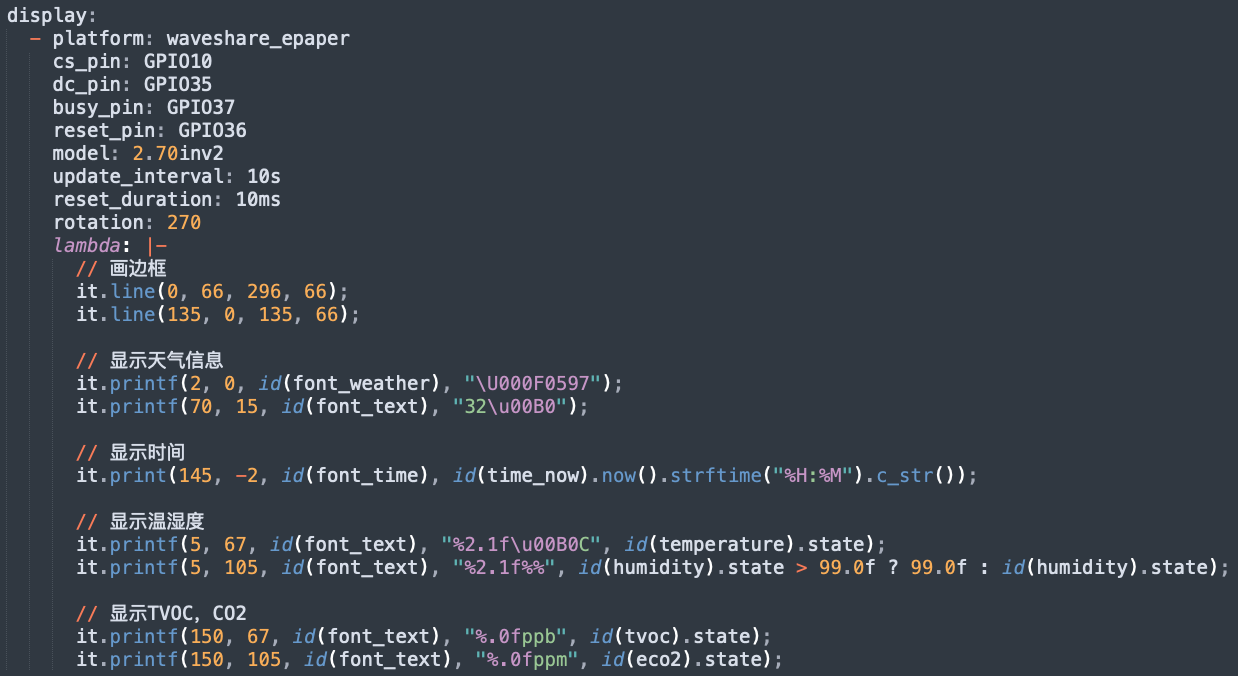
The glyphs in the font configuration specifies the characters to be used, which can reduce the firmware size. The font files used are attached.
4. Low power consumption
The ESP32-S3 has a deep sleep mode current of approximately 10uA; the SHT40 temperature and humidity sensor's sleep current of 20nA is negligible, and the SGP30 air quality sensor's sleep current is 2uA. Furthermore, the 3.3V LDO uses the ultra-low quiescent current HE9073, with a quiescent current of 0.3uA; since the SGP30's voltage is 1.8V, a 1.8V LDO, also using the HE9073, is needed. Finally, voltage acquisition uses two 2.2MΩ voltage divider resistors, consuming no more than 3.3V / (2*2.2*10^6) = 0.75uA. The e-ink screen's sleep current is 5uA. Therefore, the entire system's sleep current can theoretically be controlled within 16.55uA.
Without WiFi (only WiFi is turned on once per hour to obtain weather information), the ESP32+ sensor current is approximately 80mA; with WiFi on, the current reaches 150mA. To update the time and sensor values on the e-ink display, sensor data needs to be collected and the e-ink updated every minute; this update operation can be completed within 1 second. Therefore, the ESP32 runs for 1 second per minute, sleeps for 59 seconds, and also turns on WiFi once per hour (a fixed IP address can be configured to speed up WiFi connection, the whole process takes about 2 seconds).
The average current of the entire system per hour is (((80 * 1 + 0.01655 * 59) / 60) * 58 + 150 * 2) / 60 = 6.305mA; therefore, using a 400mAh lithium battery, the theoretical battery life is 400 / (6.305 * 24) = 2.64 days. If the e-ink screen does not display the time, the refresh interval can be extended to 1 hour. In this case, the average current per hour is (150 * 2 + 0.01655 * 3598) / 3600 = 0.100mA, and the battery life can reach 400 / (0.100 * 24) = 166.7 days (5.5 months).
Power consumption can be further optimized, mainly by reducing CPU runtime. Firstly, the CPU frequency can be reduced to 40MHz. Actual testing shows that the e-ink screen refresh operation takes approximately 400ms. Subsequent refresh operations are handled by the screen driver chip, and the ESP32 entering sleep mode does not affect the e-ink screen refresh. Sensor data reading can be completed within 50ms. Therefore, we can send a sensor data reading command after each deep sleep wake-up of the CPU, obtain the latest data after 50ms, and then start refreshing the screen. After 400ms, it can enter Deep Sleep mode. Secondly, using partial refresh on the e-ink screen might further reduce the refresh time.
Note: The current code does not implement ESP32 deep sleep; this needs to be added later.
5. Shell Design:
The shell design is incomplete and needs to be completed.
6. Competition Logo Verification
7. Project Attributes:
This project is original and being released for the first time. It has not won any other competition awards.
8. Open Source License:
This project follows the MIT open source license.
9. Appendix
9.1 Font Modification:
The Acme-9-Regular font contains two versions: one is a small-spaced font without "Xtnd" ("Acme 9 Regular.ttf" and "Acme 9 Regular Bold.ttf"), and the other is a large-spaced font with "Xtnd" ("Acme 9 Regular Xtnd.ttf" and "Acme 9 Regular Bold Xtnd.ttf").
I used the small-spaced font "Acme 9 Regular.ttf" as a dedicated font for time information to reduce the space occupied by the time area, and "Acme 9 Regular Xtnd.ttf" as a font for other information.
1) Modification of Acme 9 Regular.ttf :
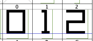
This font only needs one modification, which is to change the number 1 to a fixed width. The left side of the image below shows the data 1 before modification. Its width is smaller than the other numbers. This causes the displayed time information to shrink to the left when it includes the number 1, because the number 1 is smaller than the others. If the width of the number 1 is the same as the other numbers, this problem doesn't exist. The right side of the image below shows the number 1 after modification.
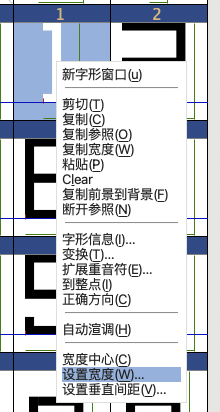
The modification method is to right-click the number 1 and select "Set Width":
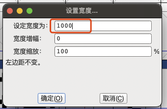
In the pop-up window, enter 1000 and click OK:
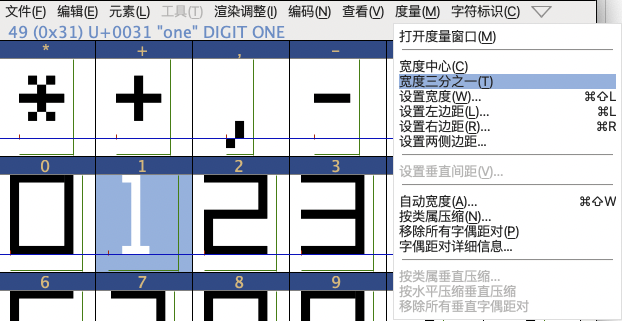
After setting the width, the number 1 is too far to the left, so you need to adjust the left margin.

Select the number 1, then select the menu "Measure" and then "Width One-Third":
Set the number 1 as follows:

Export the font settings. Click the "File" menu, select "Generate Font":

Enter the file name, click "Generate," ignore the warning window that pops up, and click as shown in the screenshot below to successfully export the font file.

2) Modification of Acme 9 Regular Xtnd.ttf:
This font mainly modifies the percentage sign "%" and the degree symbol "°" because I didn't think the original looked very good. This modification simply involves drawing the characters yourself; there aren't many techniques involved. Below are the before and after effects.


The method for exporting fonts is the same as above.
temp-detector-gpt4o.yaml
materialdesigniconswebfont.ttf
temp-detector.yaml
temp-detector.bin
waveshare_epaper.cpp
Acme-9-Regular-mod.ttf
Acme-9-Regular-Xtnd-mod.ttf
PDF_#9th LCSC Electronics Design Contest# ESP32-S3 Low-Power E-ink Indoor Air Quality Monitor.zip
Altium_#9th LCSC Electronics Design Contest# ESP32-S3 Low-Power E-ink Indoor Air Quality Monitor.zip
PADS_#9th LCSC Electronics Design Contest# ESP32-S3 Low-Power E-ink Indoor Air Quality Monitor.zip
BOM_#9th LCSC Electronics Design Contest# ESP32-S3 Low-Power E-ink Indoor Air Quality Monitor.xlsx
93192
Based on LCSC Diwenxing CW32 digital voltage and current meter
This project is for participants in the CW32 voltmeter and ammeter training camp.
It allows for manual calibration and measurement value setting.
Learning materials for this project can be found at: https://wiki.lckfb.com/zh-hans/dw
This schematic design explains

the software used.
Since I don't know how to write software, I used the software provided by juminut, and I would like to express my gratitude.
A pre-compiled hex file is attached at the bottom. It can be directly burned.
If you want to learn the code, the attached file (project.zip) contains the Keil software source code.
Five working modes are defined. The K1 key is used to switch display modes. The K2 key sets the parameter value for the corresponding mode and saves it to FLASH. The K3 key returns to mode 0.
Mode 0: Displays normal voltage and current values (the upper row of the digital tube displays the voltage value in .V or .V automatically switches,
the lower row displays the current value in _.**A). Mode 1: 5V voltage calibration setting. The upper row of the digital tube displays 5.05. The lower row displays the current voltage value in _.V or ._V. In this mode, the multimeter should be set to 5.00V to measure the measured bit. After pressing the K2 key, the current value is calibrated to 5V.
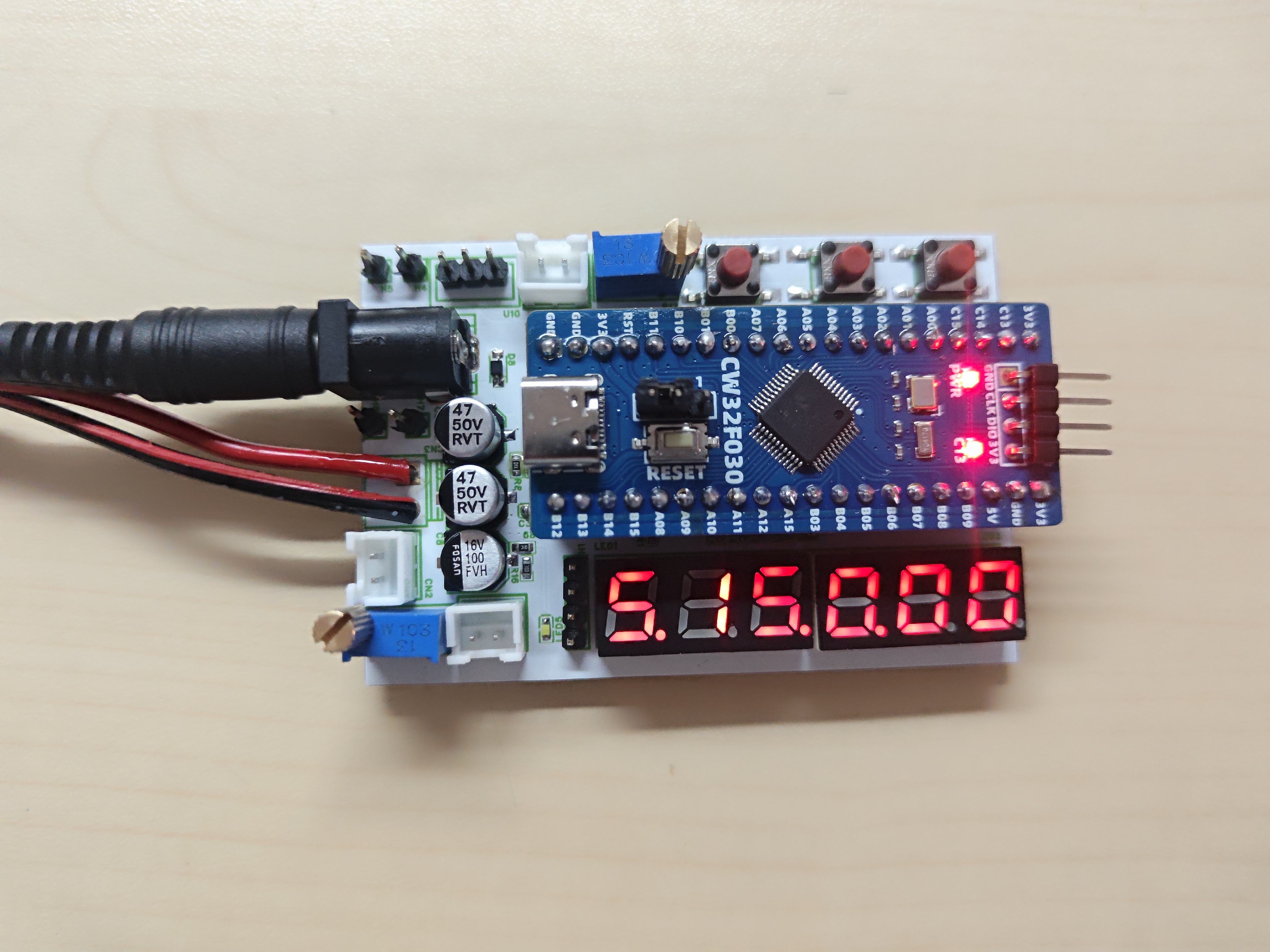
Mode 2: 15V voltage calibration setting. The upper row of the digital tube displays 5.15. The next row displays the current voltage value as _.V or ._V. In this mode, the multimeter should be set to 15.0V when measuring the measured part. Pressing the K2 key will calibrate the current value to 15V.
Mode 3: Current 0.5A calibration setting. The upper row of the digital display shows A.0.5. The next row displays the current current value as _.**A. Pressing the K2 key will calibrate the current value to 0.5A.
Mode 4: Current 1.5A calibration setting. The upper row of the digital display shows A.1.5. The next row displays the current current value as *.**A. Pressing the K2 key will calibrate the current value to 1.5A.
Learning video: https://www.bilibili.com/video/BV1Fw4m1C7db/?spm_id_from=333.788&vd_source=66ea5d947e141827003216742d914809
Software author link: https://oshwhub.com/juminut/voltage-ammeter-7347744a
GPIO.hex
PDF_Based on LCSC CW32 Digital Voltage and Current Meter.zip
Altium_Based on LCSC CW32 Digital Voltage and Current Meter.zip
PADS_Based on LCSC CW32 Digital Voltage and Current Meter.zip
BOM_Based on LCSC Diwenxing CW32 Digital Voltage and Current Meter.xlsx
93193
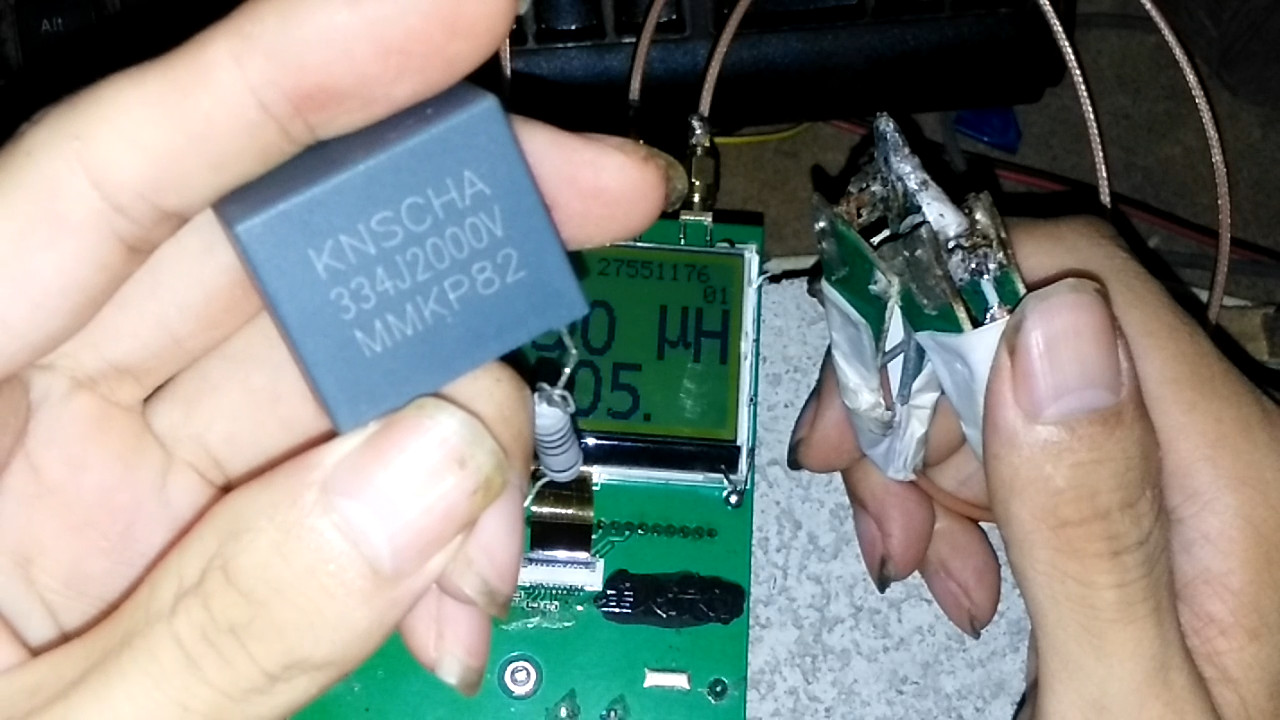
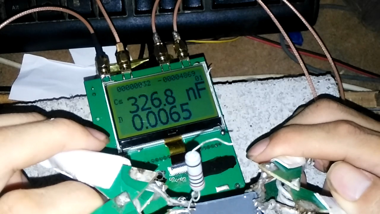
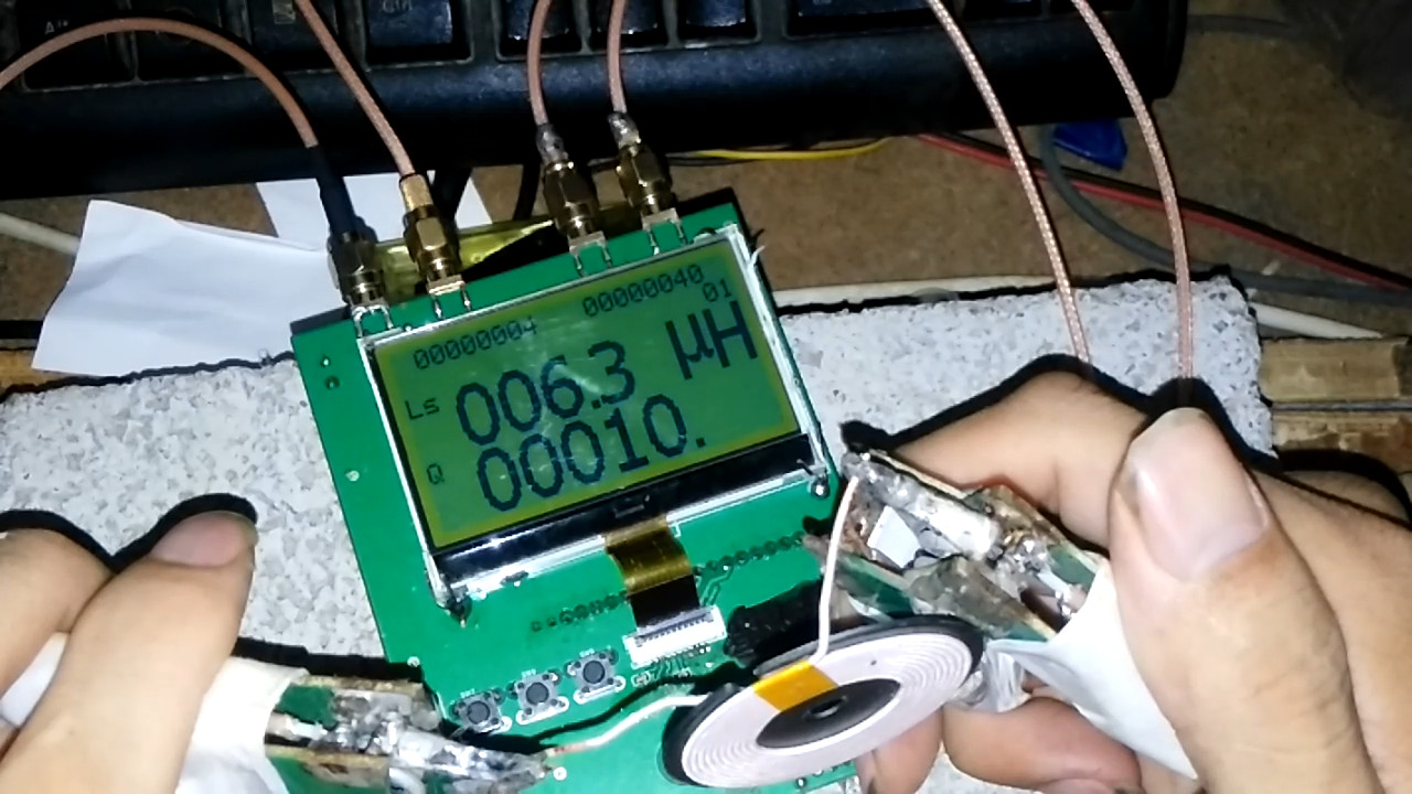
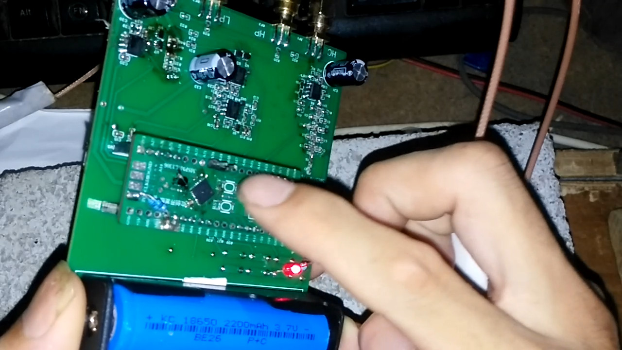
MSPM0L1306 adapter board capacitance and inductance measurement
Failed to build a capacitance and inductance measuring device using the Dizhengxing MSP0L1306 development board.
Source code and firmware.zip
Real product video.mp4
PDF_MSPM0L1306 Adapter Board Capacitance and Inductance Measurement.zip
Altium_MSPM0L1306 adapter board for capacitance and inductance measurement.zip
PADS_MSPM0L1306 adapter board for capacitance and inductance measurement.zip
BOM_MSPM0L1306 adapter board capacitance and inductance measurement.xlsx
93195
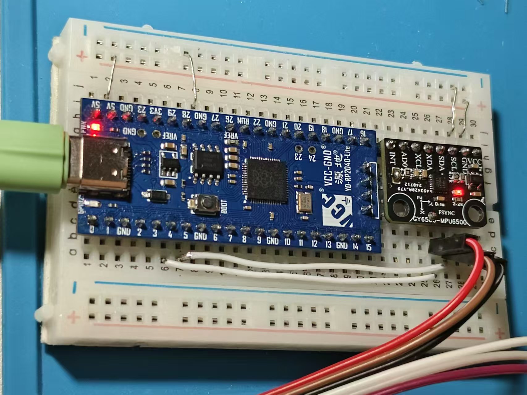
MPU6500 module
The gyroscope and accelerometer, 6-axis, have been successfully verified.
Communication is normal, and raw data can be read.
Software attitude calculation is implemented based on this module.
Test video:
https://www.bilibili.com/video/BV1yE4m1R7ev/?spm_id_from=333.999.0.0&vd_source=6e817c3943bff9f1749caaa76f60e5dc
PDF_MPU6500 module.zip
Altium_MPU6500 module.zip
PADS_MPU6500 module.zip
BOM_MPU6500 module.xlsx
93196
electronic


 京公网安备 11010802033920号

 RE5VL27A-RF


