I. Team Introduction: Team members
from the Applied Electronic Technology program at Wuhan Transportation Vocational College (Qin Yunfa, Li Xian, Yang Jiale) participate.
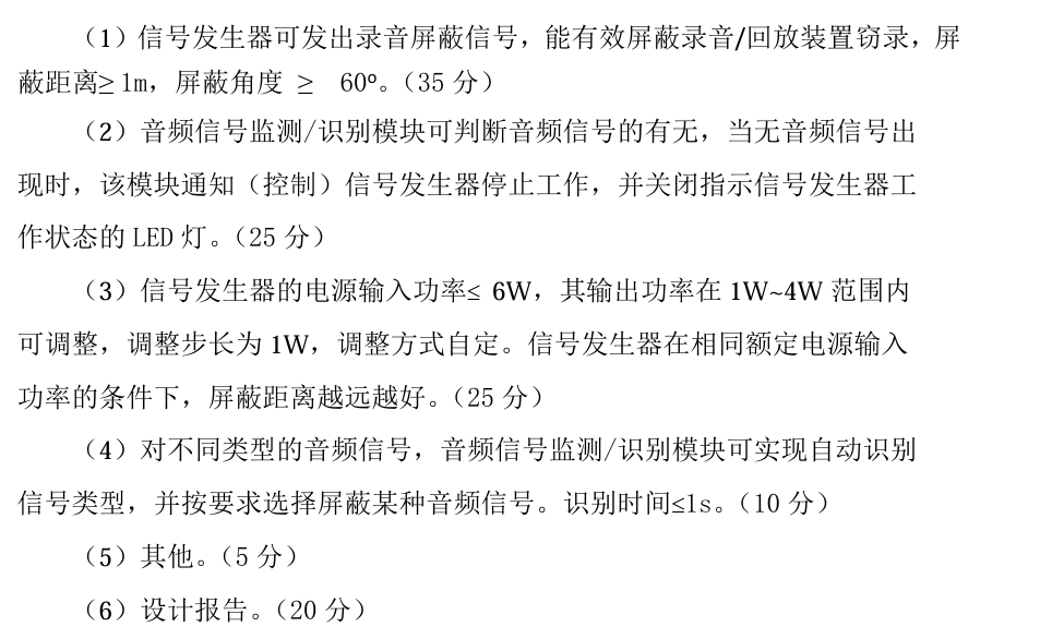
II. Project Requirements
III. Design Summary
: Complete ultrasonic shielding that effectively blocks input sound signals.
IV. Project Analysis:
1. Complete basic ultrasonic shielding.
2. Building upon ultrasonic shielding, complete the following (increasing the propagation distance and angle by 1m is full marks) (achieve sound detection and silence by pausing the speaker's voice).
3. Adjust the power step to 1W (with the input power to the shield less than 6W and the output power 1-4W)
. The
following is a description of the ultrasonic shielding device, which requires sound type identification and shielding selection .
The principle is based on the high-frequency signal of ultrasound causing the phone's microphone to vibrate. When other sounds arrive, their low frequency is insufficient to change the microphone's vibration amplitude (the change is minimal), resulting in continuous microphone vibration and a loud, noisy sound. An
operational amplifier drives the ultrasonic transmitter, similar to a speaker, but requiring sound type identification and shielding selection. Fourier transform can be used, but technical limitations exist. This is an open-source project hoping for improvement from users. The
hardware circuit components
are as follows:
1. Multiple ultrasonic transmitters (T-type) connected in parallel (the more, the better).
2. Skystar STM32F401 development board (youth version), other 401 boards can also be used, but LCSC's is truly excellent
. 3. Sound detection module, LM358, LM393.
4. Single-channel 5W power amplifier chip LTK5128. This chip has an enable pin that can be directly driven to turn off by high and low levels with low latency. Note: If high and low levels are used to control the relay, the latency will be very high, 1-2 seconds.
(Other power amplifiers or H-bridges (LM298N motor drivers can also be used), half-bridges, and full-bridges can also be used.)
5. Multiple DuPont wires, header pins, header nuts, LEDs, 1k and 2k base resistors, etc.
VII. The program
first acquires ambient white noise (voltage value), then uses an ADC to collect the sound sensor signal, and then outputs high and low levels to control the LED to indicate the on/off state of the shield. The principle is that the LED is pulled up by a resistor, and a low level turns it on, and a high level turns it off, driving the enable pin of the LTK5128 to control the on/off state. VIII. See the attached document for
a physical demonstration . IX. Precautions: This is an improved version of the PCB, but two buttons have not been tested. Please use with caution. X. See the attached document for a demonstration video . XI. Attachment Contents: Attachment 1: Sound LED On/Off Demonstration; Attachment 2: Real-time Recording of Ultrasonic Shielding; Attachment 3: Test Room Title (Approximate); Attachment 4: Physical Demonstration; Attachment 5: Source Code


 京公网安备 11010802033920号

 ARD6004HQ


