Main functions:
1. Actively upload data to the computer after detecting voltage (0~5V) or current (0~20mA).
Design points:
1. Designed using the CW32 Earth Star development board. To omit the power supply circuit, a 5V TTL serial port is used for power supply.
Of course, an external 5V power supply can also be used, but it must share a common ground when communicating with the computer.
2. Do not copy, do not copy, do not copy.
Circuit design and circuit principle:
The circuit diagram in this project is simple, so the layout is arbitrary and the components are placed messily. I'm too lazy to tidy it up, so please bear with it.
1. The power supply circuit
must not be used in industrial scenarios with 24V or 36V power supply. This project is for learning the principle of ADC and the use of CW32 microcontroller, so not many protection circuits have been made. Therefore, you must be extra careful when testing.
2. Main control chip:
This project uses CW32F030 as the main control chip
. 3. Voltage acquisition circuit:
This project uses a voltage divider circuit to achieve voltage acquisition. The design can acquire voltage from 0 to 5V. The current configuration is the highest acquisition voltage of 5V.
The voltage divider resistor in this project is designed to be 10K+10K, so the voltage division ratio is 1:1.
The selection of voltage divider resistors mainly needs to consider the following aspects:
1. The maximum value of the voltage to be measured. The factory setting in this project is 5V.
2. ADC reference voltage. In this project, it is 2.5V. This reference voltage can be configured through the program.
3. Calibration: For calibration, a 20k adjustable resistor was added to this design (adjusted to 10k).
Based on the above data, the resistance of the voltage divider resistor can be calculated using the parameters:
1. Calculate the required voltage division ratio: i.e., ADC reference voltage: design input voltage. Using known parameters, we can calculate 5V/5V=1.
2. Calculate the high-side resistance: i.e., low-side resistance/voltage division ratio. Using known parameters, we can calculate 10K/1=10K.
3. Select a standard resistor: Select a resistor slightly higher than the calculated value. The calculated value is 10K, and I chose a 20k adjustable potentiometer.
If the maximum voltage to be measured needs to be adjusted in actual use, the following will be explained:
1. Assuming the measured voltage is 10V, we choose to adjust the resistance of the 20k potentiometer to expand the range.
2. Knowing that the voltage division ratio of the selected resistor is 0.5, we can calculate 10V*0.5=5V by reverse deduction of the formula. Therefore, our original potentiometer at 10k is not enough, and it needs to be adjusted to 30k. Therefore, we chose a smaller potentiometer. Therefore, our data acquisition card can only acquire a maximum voltage of 7.5V.
Considering the potential fluctuations in the power supply under test, a 0.1uF filter capacitor is connected in parallel with the low-side voltage divider resistor in the circuit
design to improve measurement stability. All resistors in this design are designed as pin-type resistors for easy replacement and future resistance/range changes.
Special attention needs to be paid to PCB layout; I did not use copper plating.
4. Current Acquisition Circuit:
The sampling current designed for this project is 20mA, and the selected sampling resistor is 250 ohms.
The following aspects should be considered when selecting the sampling resistor: (In reality, my current sampling circuit is completely the same as the original voltage sampling circuit)
1. The maximum value of the current to be measured, which is 20mA in this project. 2.
Calculation of the current sensing resistor value: 5V/20mA = 250 ohms.
3. The power consumption of the current sensing resistor; a suitable package should be selected based on this parameter. I used a 250-ohm 1W high-precision resistor and enlarged the pads to allow for the replacement of resistors with different resistance values.
4. Relationship between current and voltage on the current sensing resistor: 0-5V and 0-20mA are standard industrial signals, such as the standard signal of a pressure transmitter, which is generally a current signal (though voltage signals are also possible). I simply converted them to each other. If the target signal is 0-5V, I can directly send it to the microcontroller. If it is 0-20mA, we added a 250-ohm sampling resistor between its two terminals, so it becomes 20*250/1000=5V. Therefore, my voltage and current sampling circuits are the same, because voltage and current are directly proportional.
5. This project aims to learn how to use the ADC function of a microcontroller, so power supply filtering and voltage regulation are not considered.


ADC Acquisition + Serial Communication.zip
b4e6803ab5d5c2ab9e09bc4454acfb7c.mp4
PDF_CW32 Data Acquisition Card.zip
Altium_CW32 data acquisition card.zip
PADS_CW32 Data Acquisition Card.zip
BOM_CW32 Data Acquisition Card.xlsx
93267
Temperature detection based on STC8H1K08
A temperature detection system based on the STC8H1K08 chip is used to monitor the temperature in the environment in real time and can output the results through a display screen or serial port.
Design: The STC8H1K08 microcontroller is used as the core processor. Embedded C programs are written using Keil to implement temperature data reading and processing.
Applications: Indoor environmental monitoring: homes, offices, laboratories, etc. Industrial automation: production workshops, warehouses, etc.
pro.hex
PDF_Temperature Detection Based on STC8H1K08.zip
Altium-based temperature detection using STC8H1K08.zip
PADS_Temperature Detection Based on STC8H1K08.zip
BOM_Temperature Detection Based on STC8H1K08.xlsx
93268
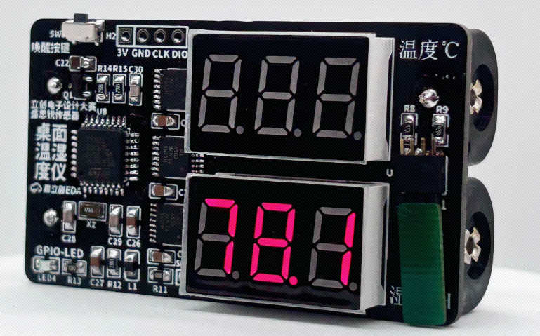
Simple Temperature and Humidity Detector - LCSC Online Training Camp
LCSC Electronics Competition - Simple Temperature and Humidity Detector
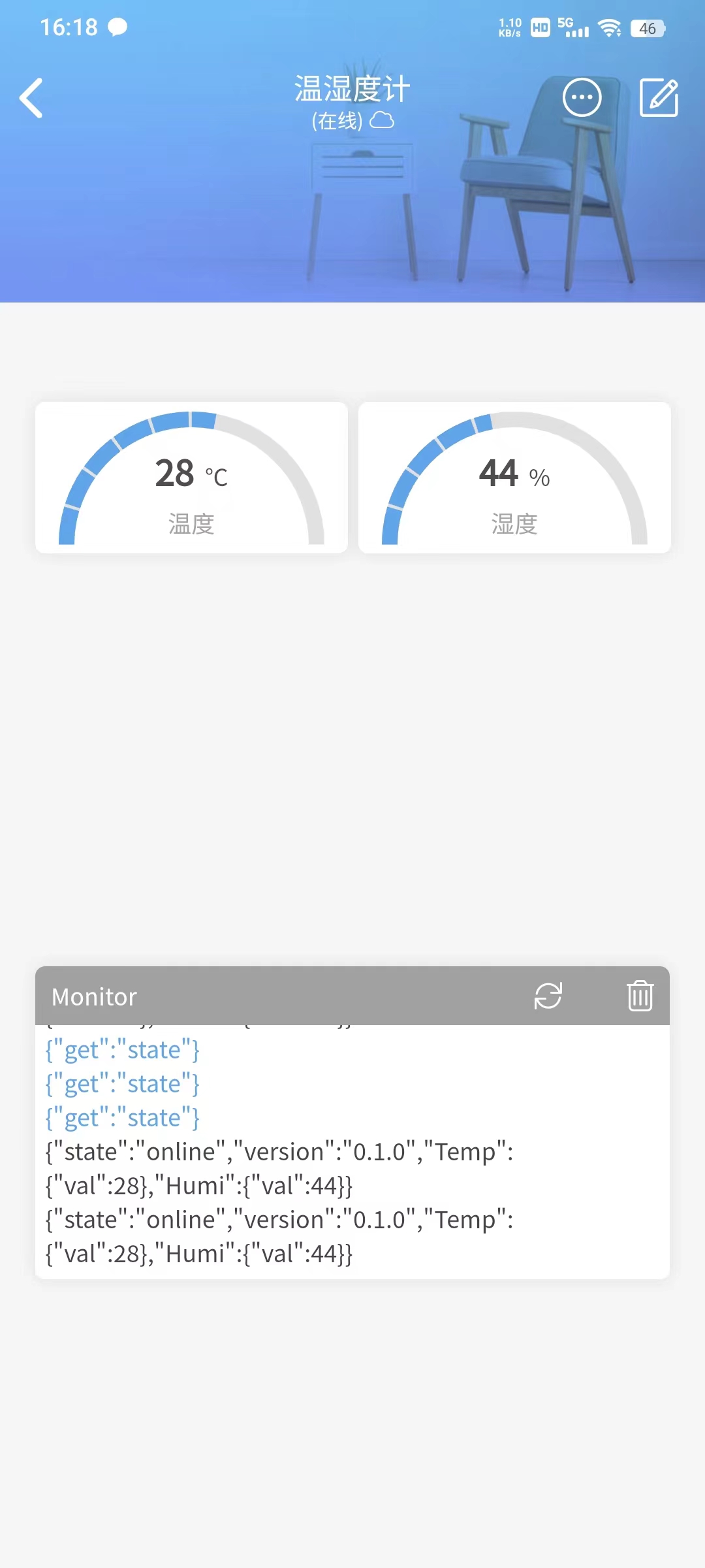
This
desktop temperature and humidity meter uses an SHT40 microcontroller to detect indoor temperature and humidity. Data is displayed using two 3-digit common-cathode LED displays. It is powered by two AA batteries and remains in sleep mode when not in use. The estimated lifespan is 6 months.
The project uses the STM32G030K6T6 chip as the main control chip. This chip uses an ARM-Cortex-M0+ core with a maximum frequency of 64MHz, 32KB of Flash and 8KB of SRAM, and operates between 2.0V and 3.6V, which is more than sufficient for a desktop temperature and humidity meter.
All code in this project is generated using STM32CubeMx software, which is simple and easy to use.
Considering
that most students learning this project are beginners and have limited experience with the G0 series, and that online resources for the G0 series are less abundant than for the traditional C8T6, STM32CubeMx software is used directly for basic code generation and configuration. The graphical interface reduces learning time and allows for quick start-up. The STM32CubeMx
software
can be downloaded and installed from the official ST website or the ST Chinese website. This will provide the latest version. (ST MCU Chinese website download address,
ST website download address,
data download,
desktop temperature and humidity sensor data download,
detailed documentation tutorial link,
JLCPCB EDA Open Source and Education Documentation Center)
7-Project2.0.7z
PDF_Simple Temperature and Humidity Detector - LCSC Online Training Camp.zip
Altium Simple Temperature and Humidity Detector - LCSC Online Training Camp.zip
PADS Simple Temperature and Humidity Detector - LCSC Online Training Camp.zip
BOM_Simple Temperature and Humidity Meter - LCSC Online Training Camp.xlsx
93269
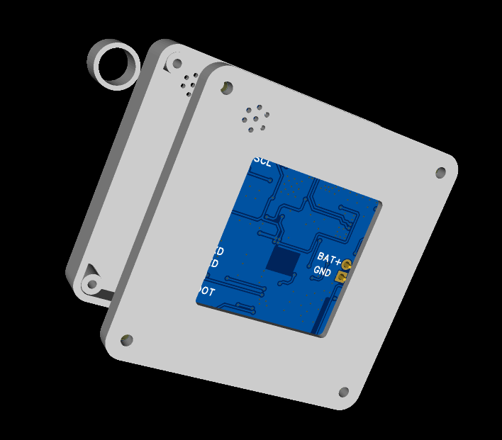
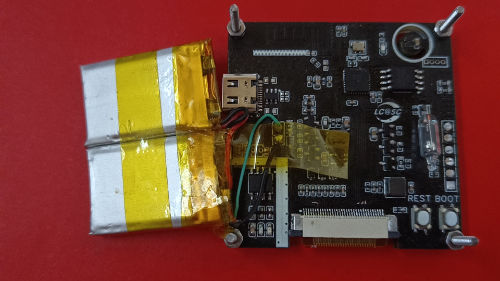
#9th LCSC Electronics Contest# IoT Thermometer and Hygrometer
An IoT thermometer and hygrometer that can connect to both Xiao Ai (Xiaomi's AI assistant) and Tmall Genie.
* 1. Project Function Introduction:
A mobile app allows users to check temperature and humidity anytime, anywhere. Settings can be customized for specific rooms or devices.
Voice input from Xiao Ai and Tmall Genie is supported, eliminating the need for close inspection; the voice assistant can provide the current temperature and humidity.
The MCU used is ESP32C3, and the sensor is Sensirion's SHT40.
* 2. Project Attributes:
This is the first public release of this project.
* 3. Open Source License:
GPL 3.0
* 4. Hardware Components:
I. Main Control Unit
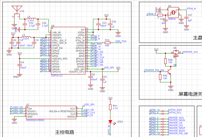
: To minimize costs, a single-module approach was adopted instead of a microcontroller + module approach.
For PCB design flexibility and cost considerations, a bare chip was chosen, allowing for flexible layout.
Therefore, the above components constitute the minimum system of the ESP32C3.
The most difficult part, the antenna, can be handled by shorting L4 with a 0-ohm resistor. C33 and C34 do not need to be soldered
. The sensor part is
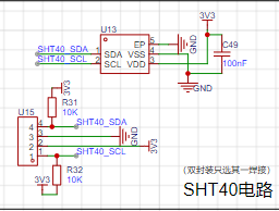
a very simple IIC circuit. Two packages are shown here; soldering one is sufficient.
When designing this circuit, 1. considering space constraints and potential interference during subsequent assembly, a bare die package was added.
2. considering the small chip size and the difficulty of manual soldering, a package with a board was also added.
This way, at least for this module, the problems are solved, avoiding the need for additional board fabrication and wasting time and materials.
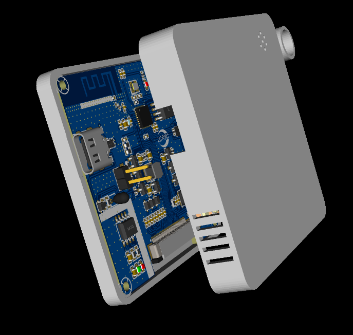
The screen driver part
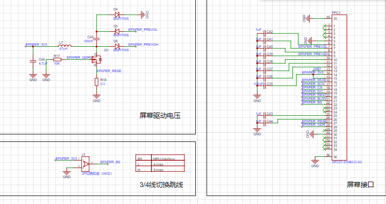
is simple; it ensures the screen functions normally. See the attachment for details. The
charging and discharging part:
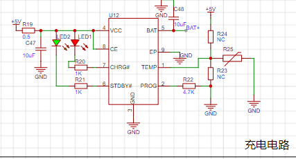

Figure 1 shows the 4056 charging circuit with an added NTC resistor. If battery temperature detection is not required, R24 is disconnected, and R23 is shorted for normal charging. The
charging current is controlled by R22. Due to the small battery capacity and the significant heat generated by a large charging current, which could affect the sensor, the charging current is around 250mA-300mA.
Figure 2 shows that to prevent damage to the device from simultaneous charging and discharging, an external charger is used during charging.
V. The step-down circuit
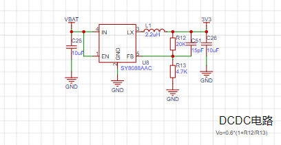
uses a DC-DC converter because it has high conversion efficiency, low power consumption, and small voltage drop, making it suitable for battery-powered devices.
To further reduce power consumption, the voltage can be lowered. Testing showed that the ESP32C3 cannot operate below 3V (consistent with the manual).
Therefore, the voltage is set to Vo = 0.6 * (1 + 20 / 4.7) = 3.15V.
VI. Powering off the module is necessary


because the screen does not need to be constantly refreshed, and the battery voltage does not need to be constantly sampled. The power is only turned on when the screen needs to be refreshed or the battery voltage needs to be sampled, thus saving energy.
The on-resistance of the MOSFET is very small and has virtually no impact on downstream devices.
A transistor pulls down a resistor, which can release the I/O when the power supply to the subsequent stage is not needed, and can automatically maintain the off state.
VII. Wake-up Switch
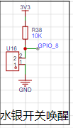
: A mercury switch is used here. When the device is tilted backward, it wakes up and updates temperature and humidity data in real time.
Some angle sensors (such as the commonly used MPU6050) can also be used, but there are many limitations: 1. They are relatively expensive; 2. I/O is limited.
It is particularly important to note that mercury vapor is toxic, so please do not drop it.
Vibration switches or other switches can also be used.
VIII. Other Circuit Notes:
In the debugging circuit section, a USB debugging circuit was originally provided, but due to insufficient I/O, its I/O was used instead (the four resistors near the Type-C port are not soldered), so the Type-C and USB ports are only for charging.
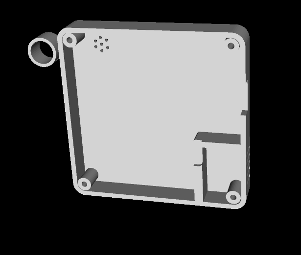
PCB Related Specifications:
Overall size 5x5 cm.
To minimize the impact of heat generation during charging on sensor readings, the longest possible isolation is used

, and grooves are cut around the sensor to reduce the impact of heat from other components on data accuracy.
The top silkscreen layer adds lines around both the charging module and the sensor. This is the part on the casing where a stretching area should be added for isolation; no components are placed in this area, allowing the casing to fit snugly against the PCB, further isolating the device's internal components from the sensor.
*5. Software Section:
Software compilation using VS Code based on ESP-IDF. Reference links (Software Section. Pinned):
1. LCSC Desktop Thermometer and Hygrometer Project Documentation (6-Temperature and Humidity Acquisition (yuque.com)
https://www.yuque.com/wldz/jlceda/ycxrhmcyxkvomgm1
2. Diandeng Technology Official Website (Diandeng Technology (diandeng.tech)
https://diandeng.tech/doc/freertos-support
3. Espressif ESP-IDF Programming Guide
Quick Start - ESP32-C3 - — ESP-IDF Programming Guide v5.3 Documentation (espressif.com)
4. ESPIDF Integration with Blinker:
ESP32 IDF + Blinker Learning Notes 2 - ESP32 Adaptation to Blinker_esp_idf Steps_esp32 blinker - CSDN Blog
5. Custom Partition List When the Font Library is Too Large to Store: ESP32 Custom Partition Table_app partition is too small for binary - CSDN Blog
https://blog.csdn.net/qq_44662794/article/details/125248484
etc.
2. Approximate Process:
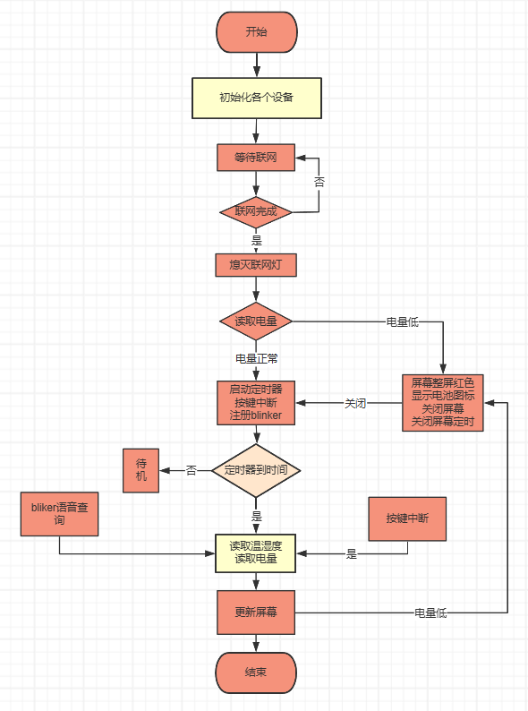
Partial Source Code
Main Function

Xiao Ai Callback

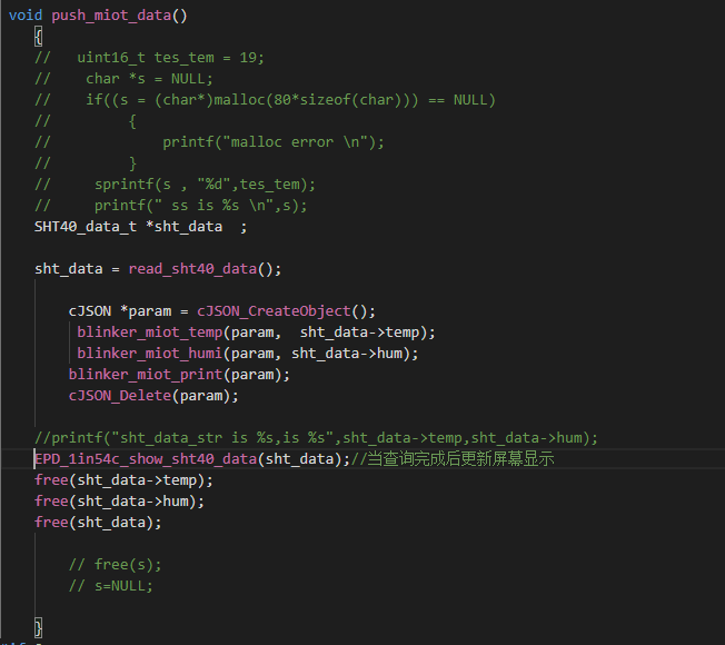
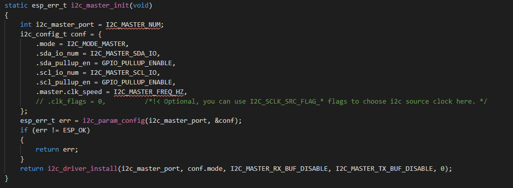
Temperature and Humidity Sensor IIC Part
IIC
Temperature Acquisition


Voltage Acquisition, Lookup Table Method for Power Acquisition

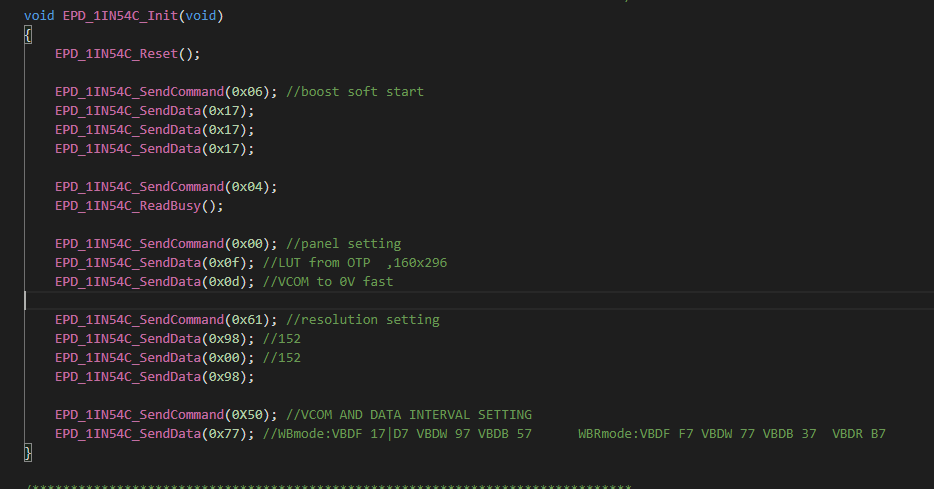
Screen Part Interface
Initialization

Screen Initialization
Program Burning
uses Espressif's official burning software, which is attached.
Burning Settings:
First step, open the burning software, select ESP32C3, select UART

. Second step, set up the burning according to this diagram.

Last step, restart the module, and you can proceed with network configuration.
After restarting, while waiting for network configuration, the board's running light will illuminate; after network configuration is complete, it will turn off.
For network configuration, either the official BLINKE software or the official Espressif software can be used.
Use SmartConfig V2 and enter your Authkey into the additional data.
If you change your Wi-Fi or Blinker account and need to reconfigure, press "rest" 5 times consecutively within 5 seconds to restore the initial settings and begin reconfiguring the network and identification code.
Note: Press the button approximately once per second, don't press too quickly. After pressing once, wait for the running indicator light to illuminate, then press it again, repeating this process 5 times. Once the running light is constantly on, open the mobile app to begin configuration.
To connect to Xiao Ai (Xiaomi's AI assistant) and Tmall Genie, you can bind your Blinker account in Mi Home and Tmall Genie for voice interaction.
The mobile app can be used to view temperature and humidity. The remaining PCB
components
are currently in use and are stacked together. A 3D shell design is also included; these will be shipped with the next sample.
Overall preview ( front

and back, inside and front) , *6; BOM list (see BOM table for details) , *7; Competition logo verification, *8; Demo your project and record a video for upload. Video requirements: Please shoot in landscape mode, resolution no less than 1280×720, format Mp4/Mov, single video size limited to 100M; Video title: LCSC Electronics Competition: {Project Name}-{Video Module Name}; e.g., LCSC Electronics Competition: "Autonomous Driving" - Team Introduction. Go to view more details >


flash_download_tool_3.9.7_1.zip
Firmware.rar
Image attachment.rar
Function demonstration.mp4
PDF_#9th LCSC Electronics Design Contest# IoT Thermohygrometer.zip
Altium_#9th LCSC Electronics Contest# IoT Thermohygrometer.zip
PADS_#9th LCSC Electronics Design Contest# IoT Thermohygrometer.zip
BOM_#9th LCSC Electronics Design Contest# IoT Thermohygrometer.xlsx
93270
#Training Camp# Simple Oscilloscope
This is based on the LCSC open-source project; everyone is welcome to learn from each other!
Simple Digital Oscilloscope:
(1) Power supply circuit: The LCSC GD32E230C8T6 development board is used to convert 5V to 3.3V via LDO.
(2) Analog front-end processing circuit: The input analog detection signal is processed and then sent to the microcontroller for identification. The specific circuit includes AC/DC coupling selection circuit, voltage attenuation circuit, and signal processing circuit.
(3) Microcontroller part: The LCSC GD32E230C8T6 minimum system development board is directly connected to the motherboard .
(4) Human-machine interaction circuit: Used to control the oscilloscope functions, including buttons, encoder, 1.8-inch TFT LCD screen, providing a foundation for the development of oscilloscope functions.
Measurement range: -80V — +250V
Refer to the official case.
Video demonstration.mp4
PDF_#Training Camp#Simple Oscilloscope.zip
Altium_#Training Camp#Simple Oscilloscope.zip
PADS_#Training Camp#Simple Oscilloscope.zip
BOM_#Training Camp#Simple Oscilloscope.xlsx
93271
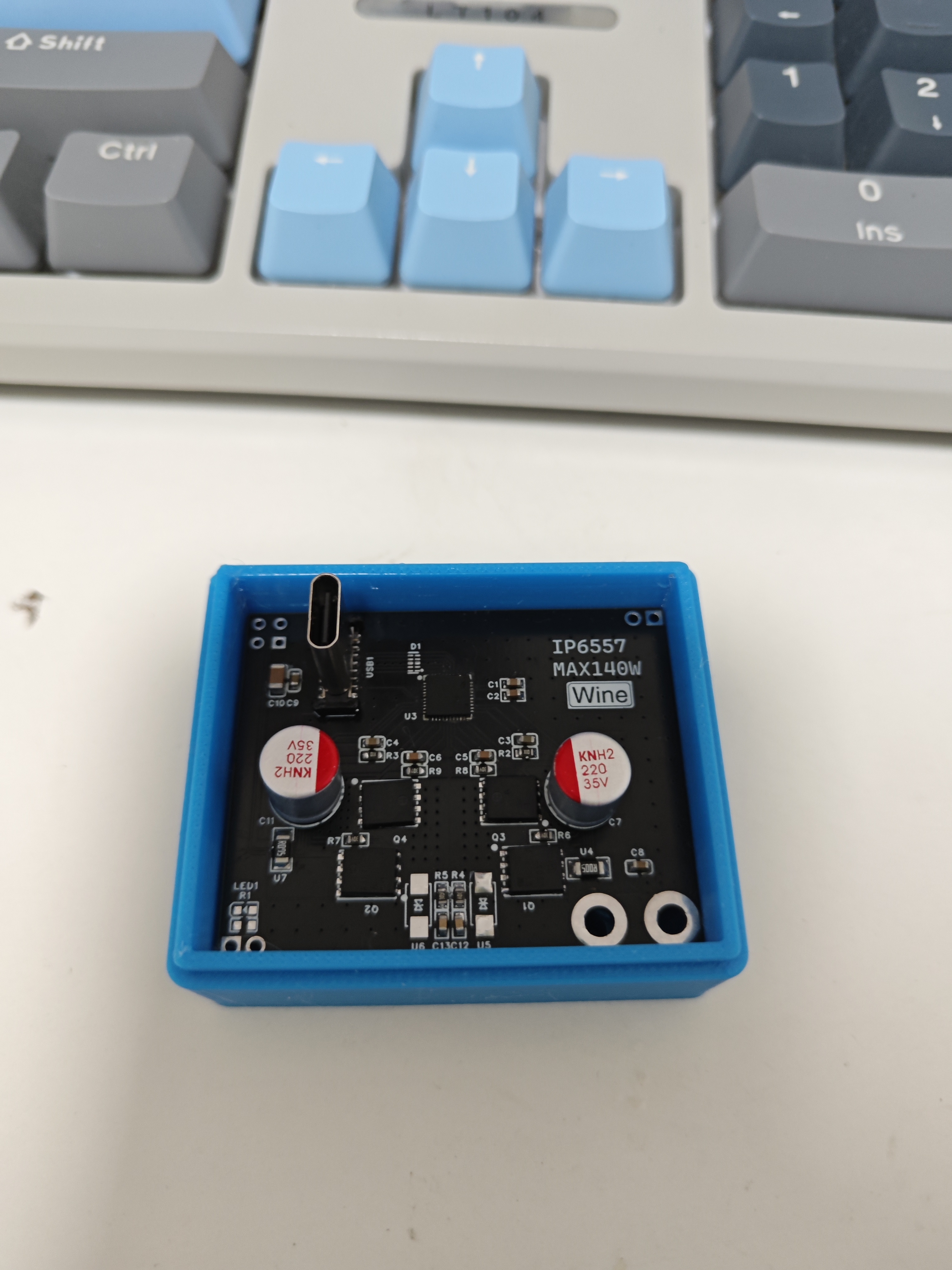
IP6557 Single-Port C PD140W
Buck-boost fast charging module supporting PD3.1/PPS/ERP28 protocols
Chip Features:
The main control chip uses Ingenic IP6557.
Input voltage range: 5V-31V,
supports 5V, 9V, 12V, 15V, 20V, 28V voltage output
PPS, supports 3.3V-21V, 10mV/step voltage output.
Integrated E-Marker cable identification and support.
Integrated multiple protection functions, including input overvoltage, undervoltage protection, output overvoltage, undervoltage, overcurrent, short circuit protection, and overtemperature protection.
Supports fast charging protocols
: Supports USB-C port PD3.1/PPS/ERP28V output fast charging protocols.
Integrated BC1.2 and Apple protocols.
Integrated QC2.0/QC3.0/QC3+/QC4+/QC5 output fast charging protocols.
Integrated FCP and HSCP output fast charging protocols
. Integrated AFC output fast charging protocol. Integrated MTK output fast charging protocol. Integrated UFCS
output fast charging protocol .
The output fast charging protocol chip costs only 6 yuan on Taobao, and the cost of the remaining components is only 24 yuan, for a total cost of 30 yuan.
The casing file can be obtained from EDA.

PDF_IP6557 Single USB-C Port PD140W.zip
Altium_IP6557 Single USB-C Port PD140W.zip
PADS_IP6557 Single USB-C Port PD140W.zip
BOM_IP6557 Single-Port Type-C PD140W.xlsx
93272
Lubancat 0W UPS Power Supply
Raspberry Pi Zero2W UPS power supply module based on IP5310
Preface:
During the development of the animal-themed movable eye system, I used the Luban Cat 0W. However, the Cat 0W's USB-C port was on the side, making it too small to fit, and there wasn't a suitable boost power supply module (dragging a power bank along would be too abstract).
Therefore, I created this integrated power supply module, which combines charging and discharging. I initially considered buying a ready-made UPS board
from Taobao
, but the price was 128 RMB and only available in Raspberry Pi-sized versions, which was prohibitive. So, I created my own
reference design using a similar approach. It uses spring-loaded pins to connect the power supply pins at the GPIO and the I2C interface to the Cat 0W.
Modifying the board size allows for compatibility with the OrangePi Zero2W and Raspi Zero2 2W series, as well as other similarly sized development boards
(for the Raspi Zero2 2W, see another dedicated project that integrates a docking station, power supply, and eMMC module).
The current discharge status can be read via the connected I2C interface (please purchase the IP5310-I2C version).
Library files and register manuals are also included. Thanks to the link to the attachment from the user "youli".
IP5310 Register Manual.pdf
IP5310 library functions.zip
Video_1722837416929.mp4
PDF_LubanCat0W Development Board UPS Power Supply.zip
Altium_鲁班猫0W LubanCat0W Development Board UPS Power Supply.zip
PADS_鲁班猫0W LubanCat0W Development Board UPS Power Supply.zip
BOM_鲁班猫0W LubanCat0W Development Board UPS Power Supply.xlsx
93273
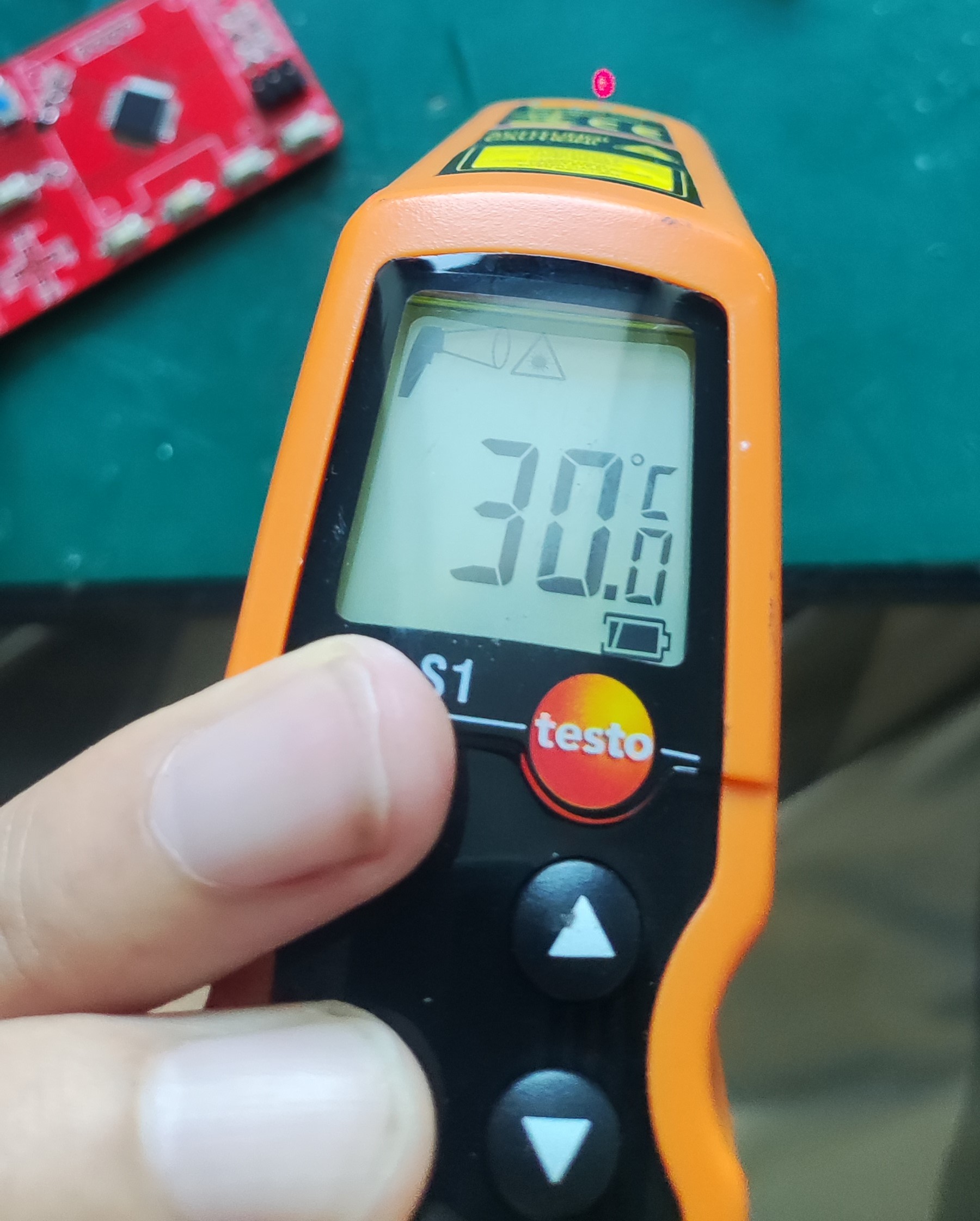
Cooling cup holder
An H-bridge circuit is constructed using four MOSFETs and their gate drivers to control the forward and reverse rotation of the thermoelectric cooler, enabling heating/cooling.
The power supply employs a PD decoy circuit, directly using a Type-C port for 12V power.
Two thermistors are also included to read the temperatures of the hot and cold surfaces.
The PD decoy circuit verification failed; regardless of the resistor matching, it only outputs 5V. I plan to redesign the board and use level control for the output voltage.
Below are the temperatures at room temperature, heating, and cooling.
Cup.zip
PDF_Cooling Cup Holder.zip
Altium_cooling cup holder.zip
PADS_Cooling Cup Holder.zip
BOM_Refrigerated Cup Holder.xlsx
93274
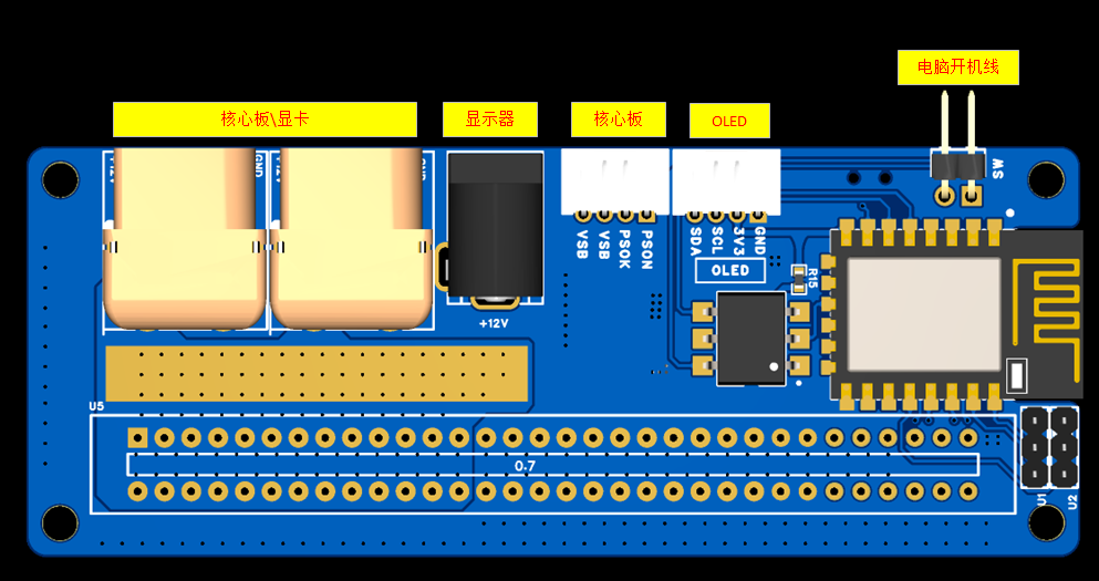
Low-cost server intelligent power supply CSPS-ATX
Using a standard server power supply, the system communicates and networks with the power supply via the ESP8266, enabling control of the power supply's start/stop, data display, and integrated remote start/stop control via computer.
Project Background: This project
aims to build a mini secondary PC using existing, old, and unused computer parts. A low-cost, small-sized power supply is needed, and a relatively reliable second-hand server power supply was chosen.
Project Reference:
[wuyu无语] Huawei 460W CSPS Power Supply esp8266 Smart Power Supply Board
CSPS-ATX12VO Smart Power
Supply Specifications:
Model: PS-2461-16H-LF
Input: 100-240V~50/60Hz 6-3A
Output:
+12V38.3A MAX
+12VSB2.5A MAX
Maximum Output Power 460W
Manufacturer: Lite-On Technology Co., Ltd.
This power supply has passed CCC certification and is 80 PLUS Platinum Standard.

Project Description:
1. The power board uses a 12VSB voltage, which is stepped down to 5V using a TPS563201DDCR DC-DC controller. This 5V powers the computer as its 5VSB voltage. An ASM1117 further steps down the voltage to 3.3V to power the ESP8226 microcontroller.
2. The ESP8226 communicates with the power supply via IIC to read power data (IIC operation address is in the power supply manual).
3. The ESP8226 uses an HTTP service to display the read voltage, fan speed, and power consumption, and allows for power supply control via a web interface
. 4. The ESP8226 controls the AQV252GA to perform power on/off operations, enabling remote power on/off.
5. The ESP8226 has a reserved interface via IIC for connecting an external OLED screen to display power data.
6. The power board has one DC connector and two XT60 connectors. The DC connector can be used to power the monitor, reducing the need for a separate DC adapter. The XT60 connectors are used to connect the core board and graphics card.
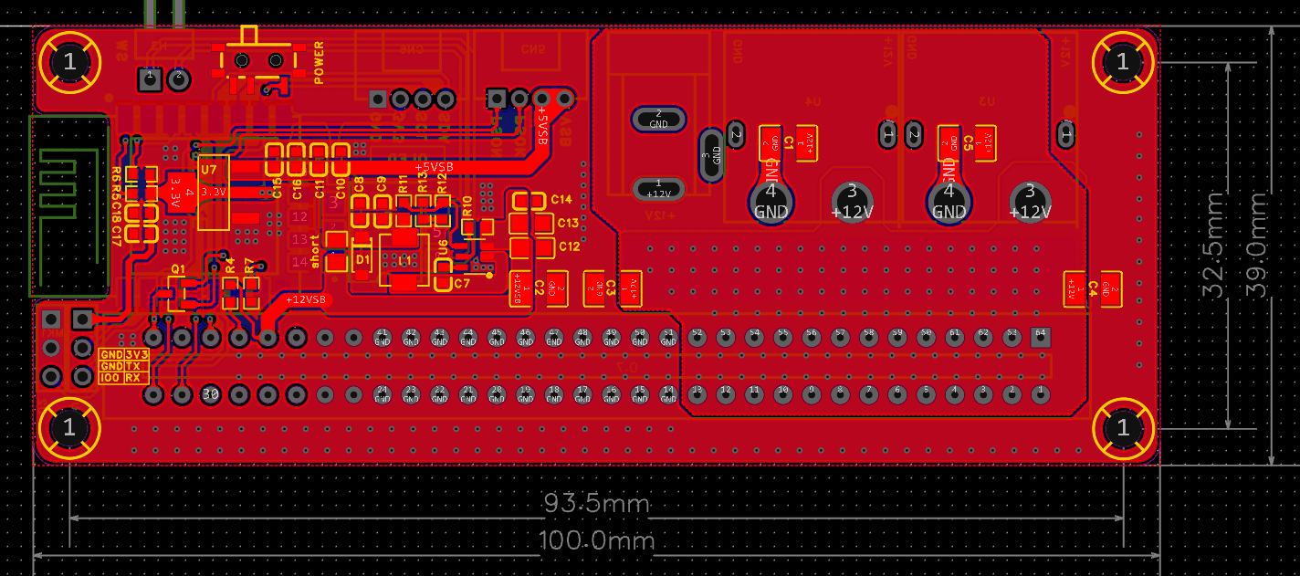
7. The PCB is a 4-layer board, and it should be able to handle 750W without any problems. Currently, I only have a 460W power supply for testing.
Note: For replicas, the shorting point does not need to be soldered. This shorting point is for use without the ESP8266, directly using 12VSB

for testing:
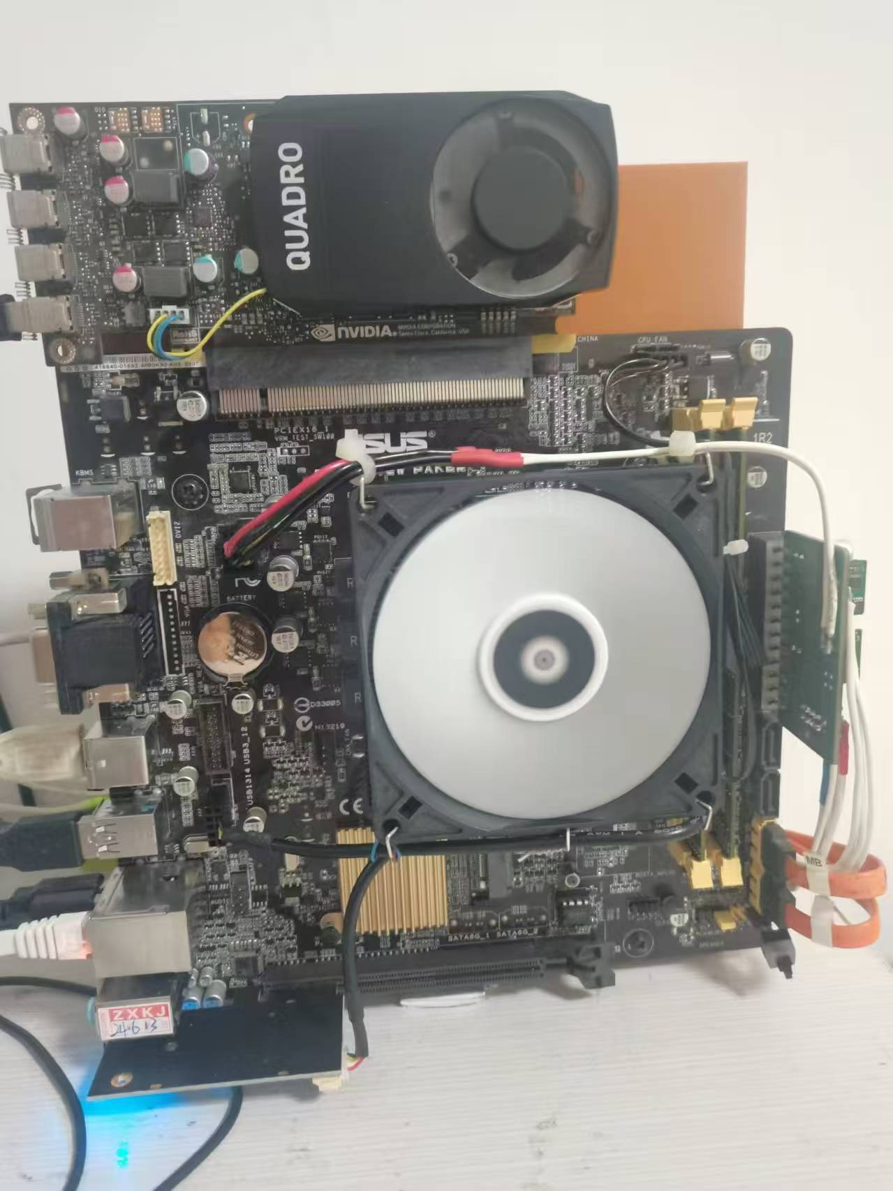
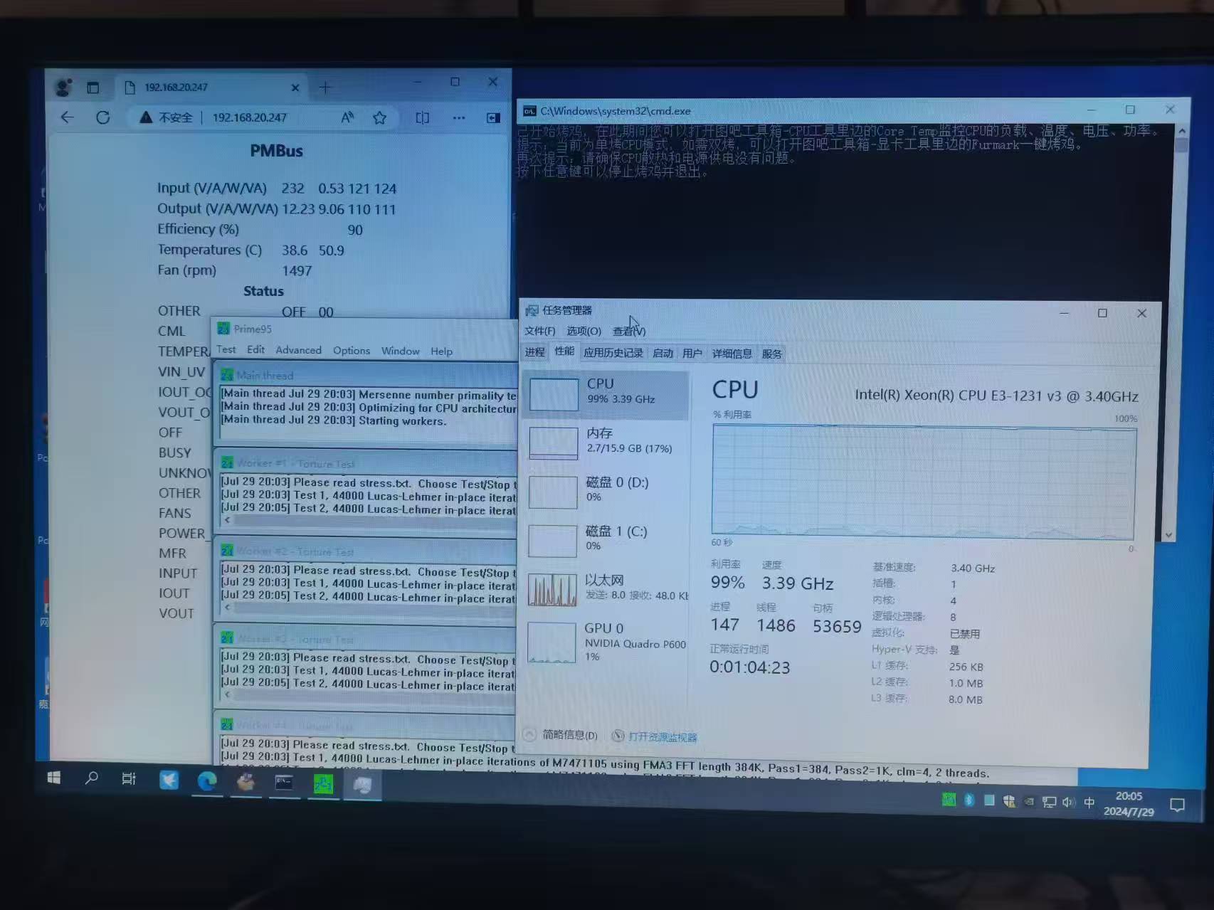
using an E3 1231V3 + B85, P600 graphics card, a 30-minute stress test, no problems. It has been working normally for 3 months. The difference between this test version and the above versions is that this test version does not have remote power-on functionality.

PS-2751-7H-LF Lite-On 750W Platinum Power Supply Datasheet (VDpdf)
PDF_Low-Cost Server Smart Power Supply CSPS-ATX.zip
Altium_Low-Cost Server Smart Power Supply CSPS-ATX.zip
PADS_Low-Cost Server Smart Power Supply CSPS-ATX.zip
BOM_Low-Cost Server Intelligent Power Supply CSPS-ATX.xlsx
93275
electronic


 京公网安备 11010802033920号

 1278110-9


