

 Voltage acquisition utilizes voltage and current division to measure voltage and current (acquisition range 0~30V).
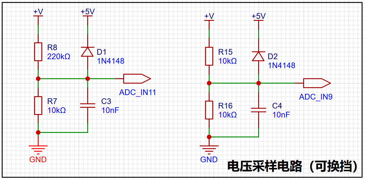
 Different voltage division ratios can change the measurement range, but higher voltage division ratios often lead to decreased accuracy. Therefore, selecting an appropriate voltage division ratio is essential.
  The ADC cannot directly measure the current magnitude and can only sample it through a sampling resistor. The maximum current design is 3A. As for why it's 100mΩ... The author can only briefly explain that a 100 milliohm resistor has a small resistance and a small voltage drop. V = I * R = 3A * 0.1Ω = 0.3V, providing a sufficiently large voltage signal input to the ADC_IN12 for voltage detection, thus indirectly calculating the current. Furthermore, P = 3A² * 0.1Ω = 0.9W, indicating relatively low power consumption and preventing overheating. Regarding
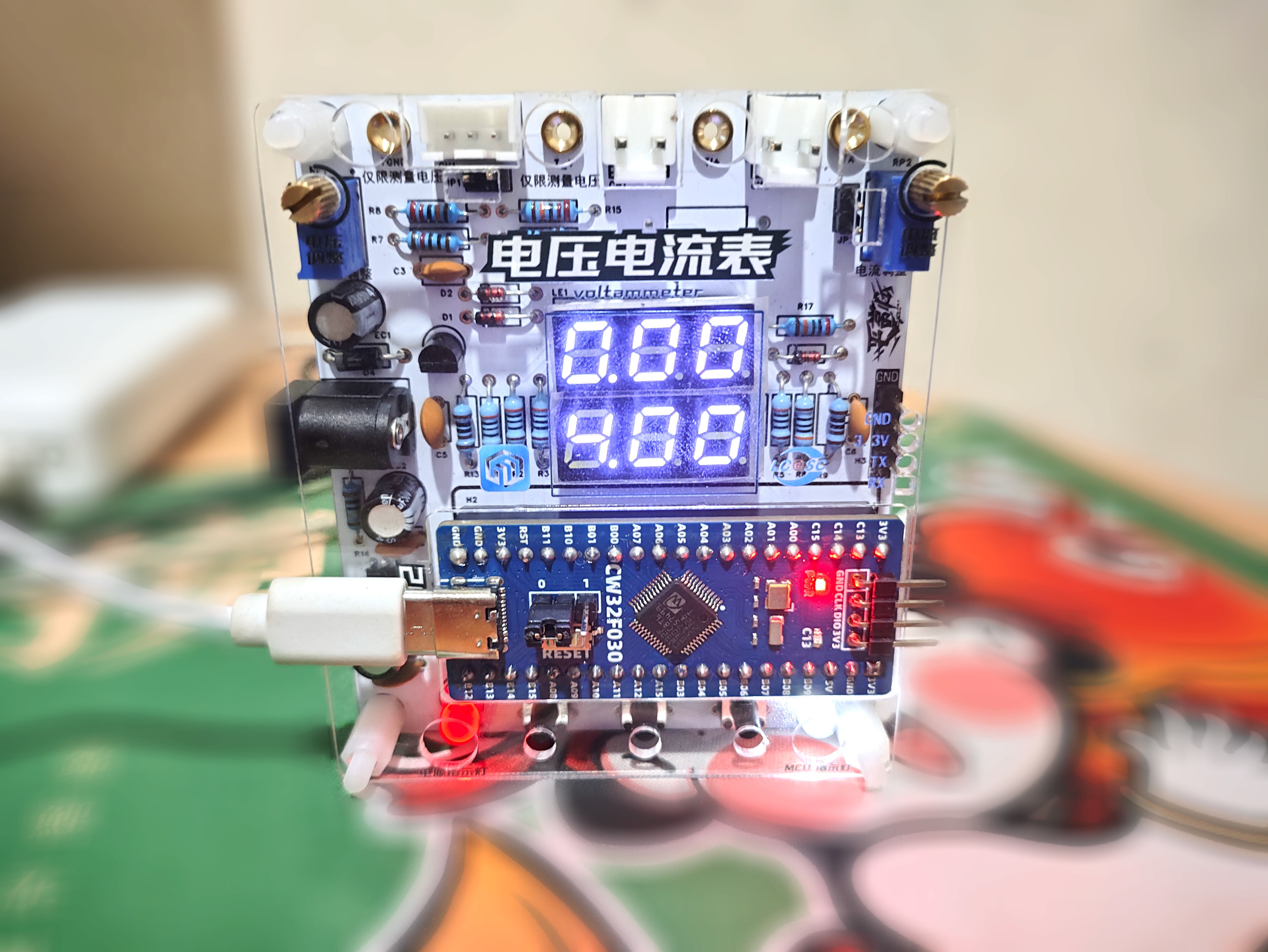
  The white digital tube is a 0.28-inch common anode white digital tube purchased from Taobao, but the BOM specifies a common cathode digital tube. Why would a mouse buy a common anode seven-segment display? Of course, it's to learn how to use a common anode seven-segment display (not really). The 2mm banana plug is a K2A33, which can be found by searching keywords. The rest were ordered from LCSC Mall based on the BOM. For detailed materials, please see the attached BOM.
  Regarding the modification of voltage and current calibration values, refer to the training camp video to modify or add a few common calibration values; I won't elaborate further.

All reference designs on this site are sourced from major semiconductor manufacturers or collected online for learning and research. The copyright belongs to the semiconductor manufacturer or the original author. If you believe that the reference design of this site infringes upon your relevant rights and interests, please send us a rights notice. As a neutral platform service provider, we will take measures to delete the relevant content in accordance with relevant laws after receiving the relevant notice from the rights holder. Please send relevant notifications to email: bbs_service@eeworld.com.cn.
It is your responsibility to test the circuit yourself and determine its suitability for you. EEWorld will not be liable for direct, indirect, special, incidental, consequential or punitive damages arising from any cause or anything connected to any reference design used.
Supported by EEWorld Datasheet
EEWorld
subscription
account

EEWorld
service
account

Automotive
development
community

Robot
development
community

About Us Customer Service Contact Information Datasheet Sitemap LatestNews


Room 1530, 15th Floor, Building B,
No.18 Zhongguancun Street,
Haidian District,
Beijing, Postal Code: 100190
China
Telephone: 008610 8235 0740
 京公网安备 11010802033920号

 GS841E18AB-100


