 Hardware Design
  This
This 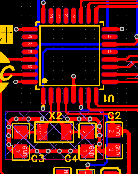 To
To 
 In PCB design, we must also pay attention to the following: power supply must pass through a filter capacitor before entering the 595 chip. Due to the dense pin arrangement, GND can be connected to the large copper area on the bottom layer using a wire and via.
  Because the digital transistor has many traces, we must avoid frequent crossings and routing to prevent affecting the integrity of the copper area. The
  sensor
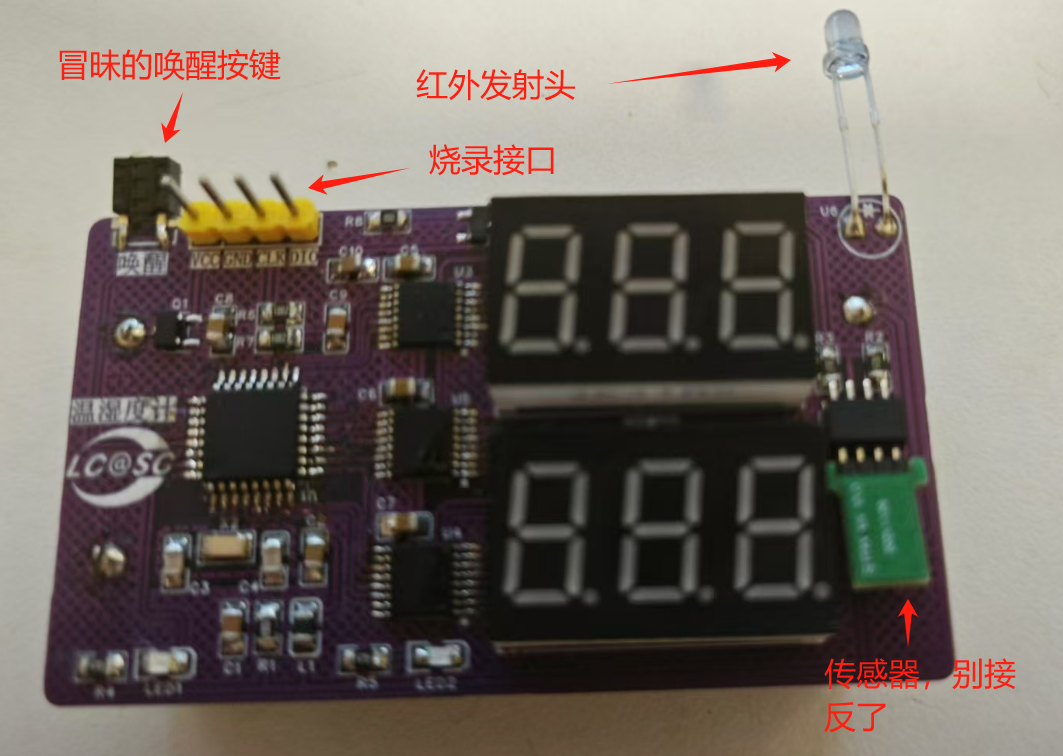
 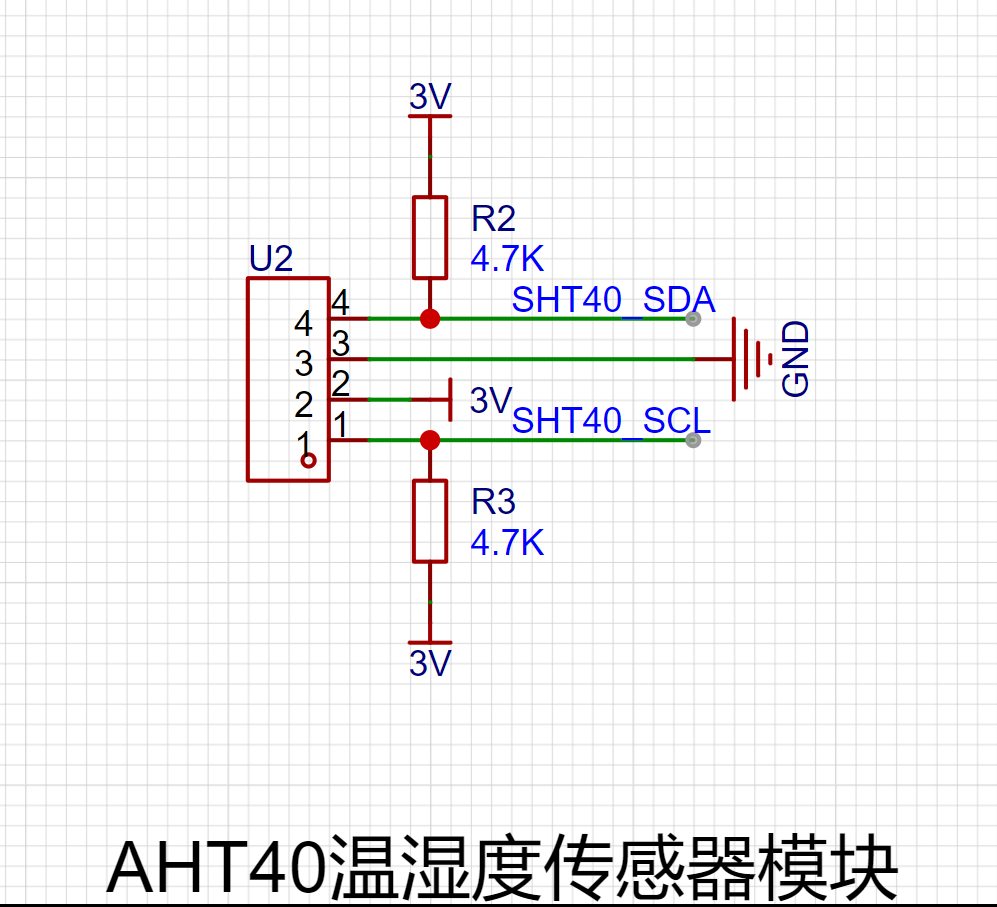 in the PCB design. It's important to note that because this is a temperature and humidity sensor, it should be kept as far away as possible from heat-generating components, and sufficient height should be provided for the module.
  Furthermore, according to feedback from group members, this module is very fragile; reverse connection will burn it
  The infrared part uses an 8550 transistor to drive the infrared transmitter. This part controls the air conditioner based on temperature changes. The oscilloscope captures the infrared transmitter signal from
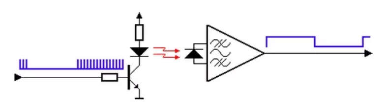 the remote control.
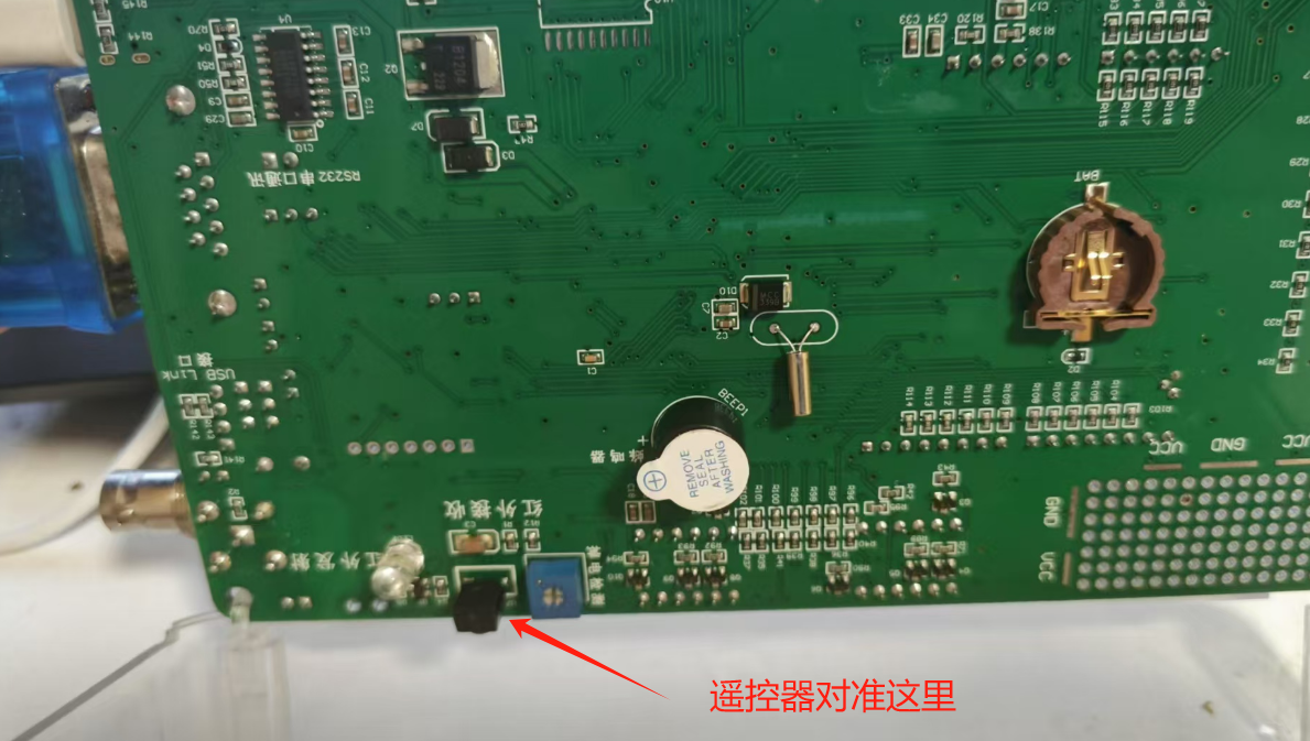
  The software design uses oscilloscope signal capture and analysis, along with data search, to roughly deduce that it uses the NEC infrared protocol: preamble + 8-bit user code + 8-bit user inverse code + 8-bit data code + 8-bit data inverse code + stop bit. Here, the infrared data is read using an STC test chamber, and the air conditioner activation data is written into the program. The STC test chamber connects to the computer. The remote control is pointed at this button , and the serial port reads the data . Different remote controls may have slightly different encodings; please operate the actual encoding. u8 SampleTime; IR_SampleCnt++; //Sample + 1 F0 = P_IR_RX_temp; //Save Last sample status P_IR_RX_temp = P_IR_RX; //Read current status if(F0 && !P_IR_RX_temp) //Pre-sample is high, and current sample is low, so is fall edge { SampleTime = IR_SampleCnt; //get the sample time IR_SampleCnt = 0; //Clear the sample counter if(SampleTime > D_IR_SYNC_MAX) B_IR_Sync = 0; //large the Maxim SYNC time, then error else if(SampleTime >= D_IR_SYNC_MIN) //SYNC { if(SampleTime >= D_IR_SYNC_DIVIDE) { B_IR_Sync = 1; //has received SYNC IR_BitCnt = D_IR_BIT_NUMBER; //Load bit number } } else if(B_IR_Sync) //has received SYNC { if(SampleTime > D_IR_DATA_MAX) B_IR_Sync=0; //data samlpe time too large


All reference designs on this site are sourced from major semiconductor manufacturers or collected online for learning and research. The copyright belongs to the semiconductor manufacturer or the original author. If you believe that the reference design of this site infringes upon your relevant rights and interests, please send us a rights notice. As a neutral platform service provider, we will take measures to delete the relevant content in accordance with relevant laws after receiving the relevant notice from the rights holder. Please send relevant notifications to email: bbs_service@eeworld.com.cn.
It is your responsibility to test the circuit yourself and determine its suitability for you. EEWorld will not be liable for direct, indirect, special, incidental, consequential or punitive damages arising from any cause or anything connected to any reference design used.
Supported by EEWorld Datasheet
EEWorld
subscription
account

EEWorld
service
account

Automotive
development
community

Robot
development
community

About Us Customer Service Contact Information Datasheet Sitemap LatestNews


Room 1530, 15th Floor, Building B,
No.18 Zhongguancun Street,
Haidian District,
Beijing, Postal Code: 100190
China
Telephone: 008610 8235 0740
 京公网安备 11010802033920号

 LPD150-024-12-VM-075


