 The circuit itself is not complex; the main difficulty lies in understanding the working principle of the core display circuit, namely the shift register + digital tube. The microcontroller can directly control the digital tube display via GPIO, but a 3-digit digital tube requires 8 GPIOs to control the 8 LEDs in a single segment + 3 GPIOs to control the switching of the 3 segments, totaling 11 valuable GPIO port resources. This is a huge burden for the STM32 microcontroller with limited pins, so a tri-state output 8-bit shift register like the 74HC595 is needed to achieve a large number of outputs with a small number of GPIO ports.
 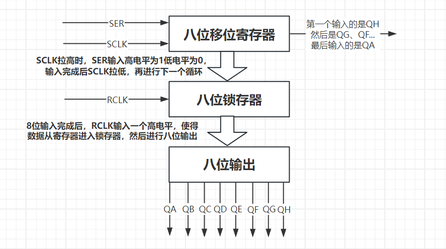 The working principle of a common-cathode 3-segment LED display: Eight pins (A, B, C, D, E, F, G, DP) simultaneously control the same segment of each of the three digits, for a total of eight segments. DIG1, DIG2, and DIG3 control the eight segments of the same digit. By alternating between these pins, a specific digit can be controlled at a time to display a designated number. For example, if the second digit needs to be 1, DIG1 and DIG3 are input with a high level to eliminate the potential difference and prevent current from flowing through the LEDs. DIG2 is input with a low level to create a potential difference, allowing the second digit to be displayed. Since the number 1 requires segments B and C to light up simultaneously, pins 4 and 7 are input with a high level, while the other six pins are input with a low level. At this point, only segments B and C of the second digit have a potential difference, causing them to conduct and light up, thus displaying the number 1 in the second digit.
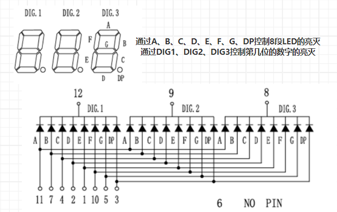
 When configuring GPIO in STM32CubeMX, it's necessary to understand the two output modes: push-pull output and open-drain output.
  In summary, push-pull outputs can output both high and low levels, while open-drain outputs can only output low levels. This project requires high/low level switching for data output, therefore push-pull output mode is used.
 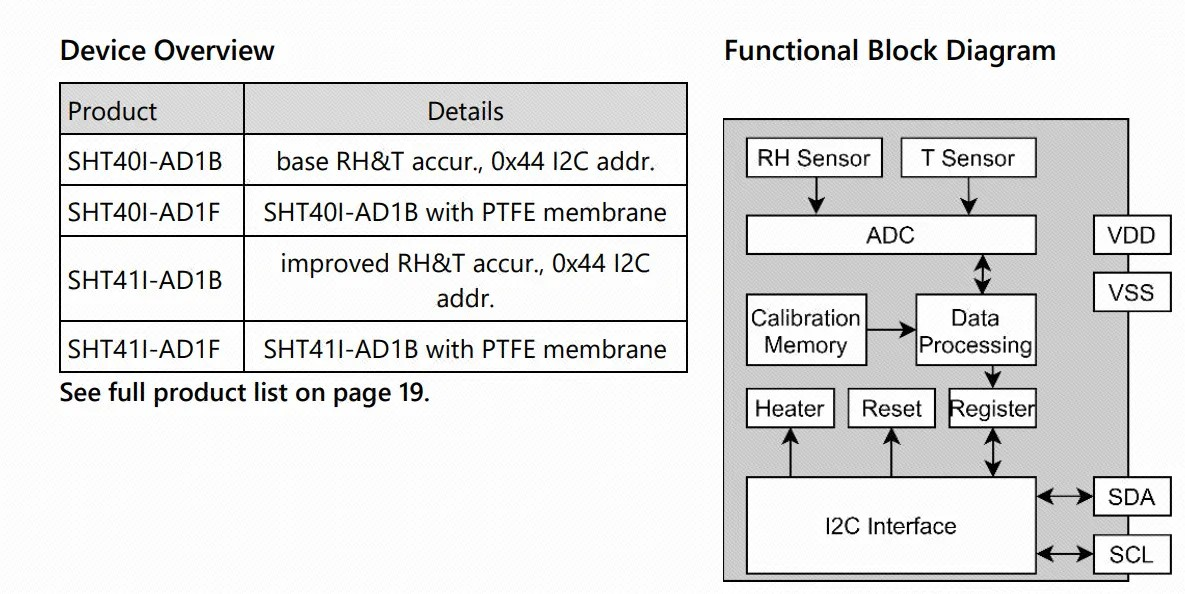 2) Understanding interrupts. An interrupt occurs when a microcontroller encounters an urgent event during operation. The microcontroller pauses its current code execution and executes code for the more pressing event. After processing, it returns to the previously paused program. The STM32G030K6T6 uses a Cortex ARM0+ core, featuring an NVIC (Nested Interrupt Controller) and EXTI (External Interrupt Event Controller), supporting four priority settings. Each GPIO can be used as an external interrupt/event trigger signal input. This combination allows the microcontroller to respond quickly to external interrupts/events. Here, the PB7 (WAKE) pin is read on the falling edge. When a falling edge occurs, the microcontroller enters interrupt handling and executes the relevant code, eliminating the need to continuously poll the button pin for a low level.
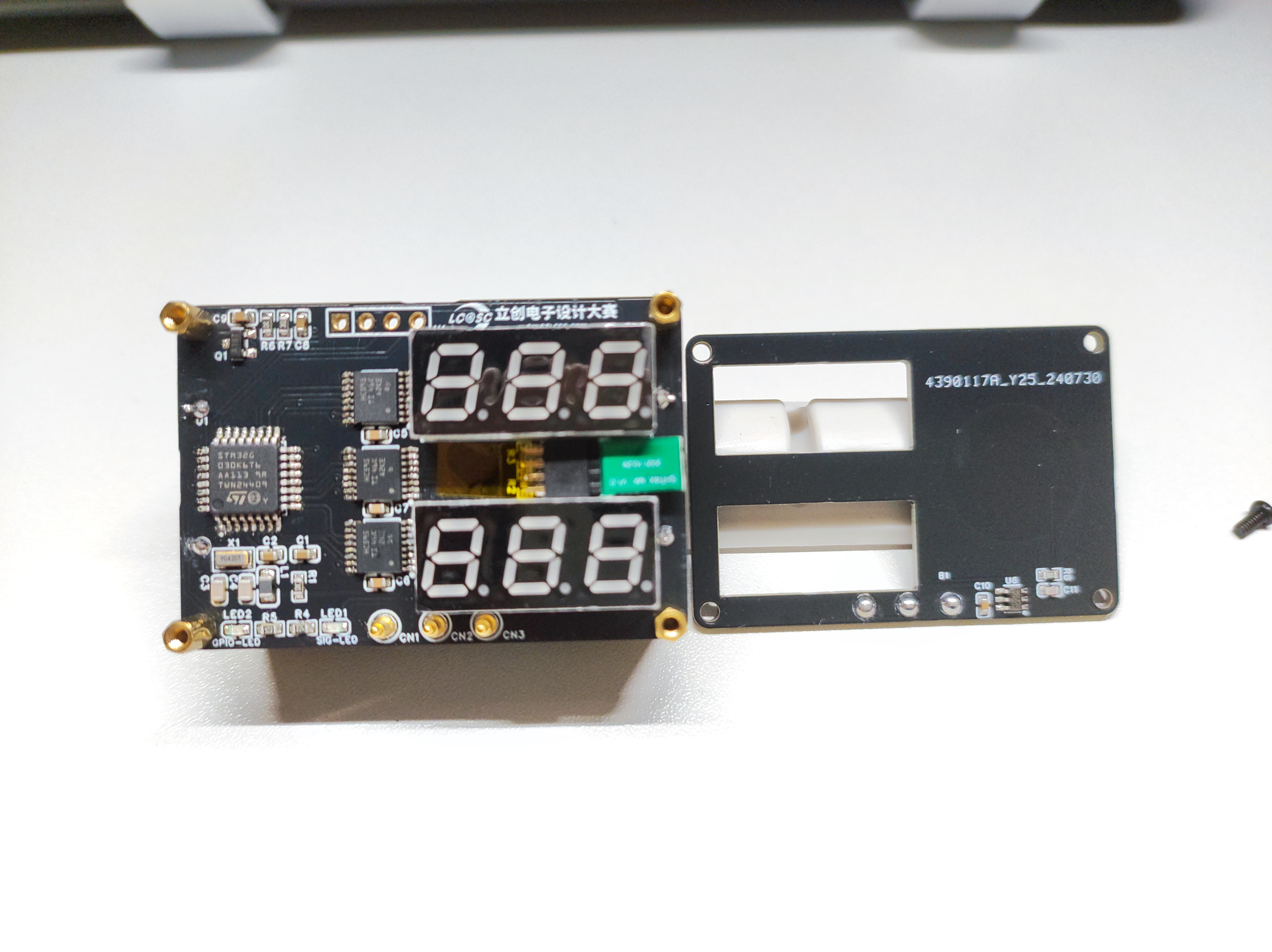
  Physical demonstration after assembly.
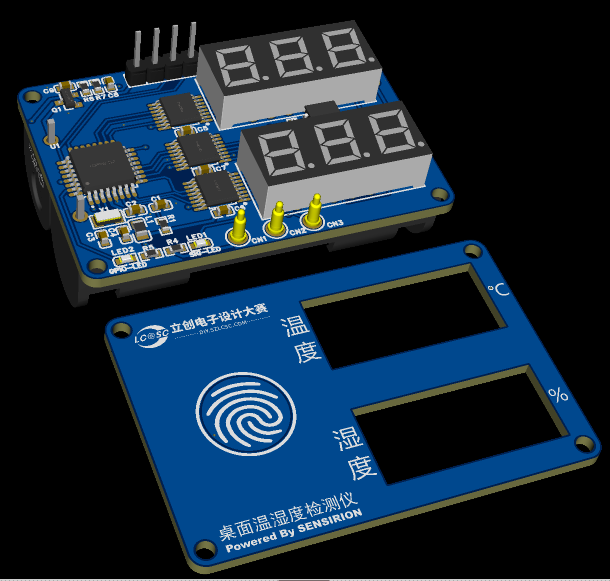
 5. Demonstration Video
All reference designs on this site are sourced from major semiconductor manufacturers or collected online for learning and research. The copyright belongs to the semiconductor manufacturer or the original author. If you believe that the reference design of this site infringes upon your relevant rights and interests, please send us a rights notice. As a neutral platform service provider, we will take measures to delete the relevant content in accordance with relevant laws after receiving the relevant notice from the rights holder. Please send relevant notifications to email: bbs_service@eeworld.com.cn.
It is your responsibility to test the circuit yourself and determine its suitability for you. EEWorld will not be liable for direct, indirect, special, incidental, consequential or punitive damages arising from any cause or anything connected to any reference design used.
Supported by EEWorld Datasheet
EEWorld
subscription
account

EEWorld
service
account

Automotive
development
community

Robot
development
community

About Us Customer Service Contact Information Datasheet Sitemap LatestNews


Room 1530, 15th Floor, Building B,
No.18 Zhongguancun Street,
Haidian District,
Beijing, Postal Code: 100190
China
Telephone: 008610 8235 0740
 京公网安备 11010802033920号

 M28C16-30WNS6


