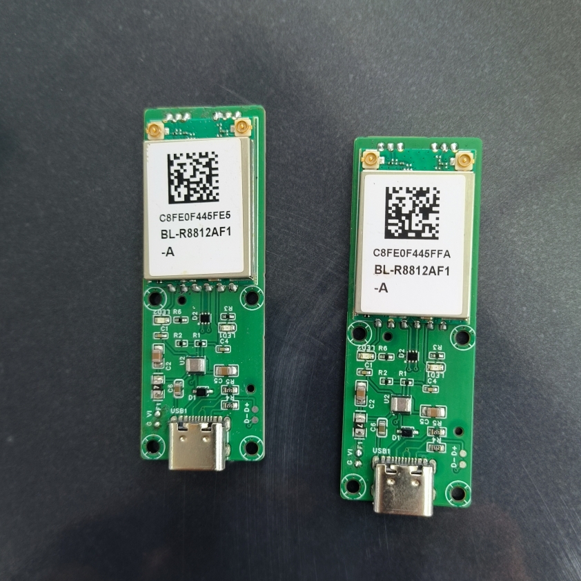
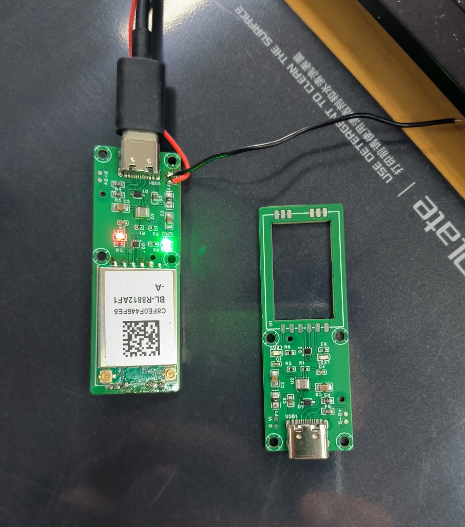
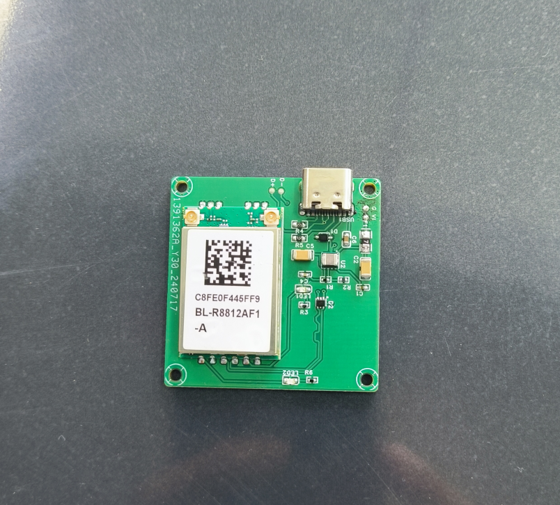
The B-Link BL-R8812AF1 network card module's baseboard with USB has been verified and is usable. Its target application is digital video transmission. The board frame can be modified as needed.
Similar modules on Taobao are large and expensive, making them inconvenient for digital video transmission applications. This baseboard has pre-drilled pads for USB and power supply, allowing direct wiring to camera modules. The power supply voltage is 3V~17V (not fully tested yet, only 7V was measured; more will be tested later). The USB-C connector allows direct connection to mobile phones. As
a 34mm W version for the ground end, it is compatible with mainstream IPC module mounting holes and can be directly stacked on the back using copper pillars.
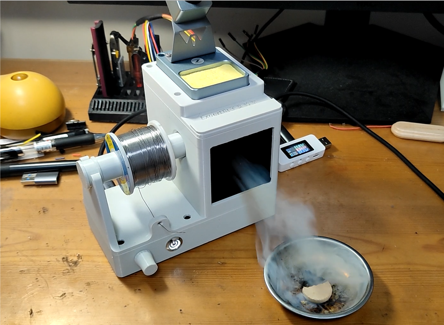
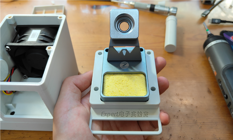
This multi-functional welding filter fan integrates welding fume filtration, solder wire storage, and a soldering iron stand.
Multifunctional Welding Filter Fan
Project Introduction:
Project Link (3D printed models can be downloaded from Github or the attachment)
Github Link: https://github.com/physicsexpert/Multi-function-welding-filter-fan
Materials Required:
Welding fan speed control PCB board (in the hardware folder) and 3D printed parts (in the model folder)

, 4 M3×45mm screws, 4 M3×10mm screws, 8 M3×6mm screws, 4

M3 nuts, 12

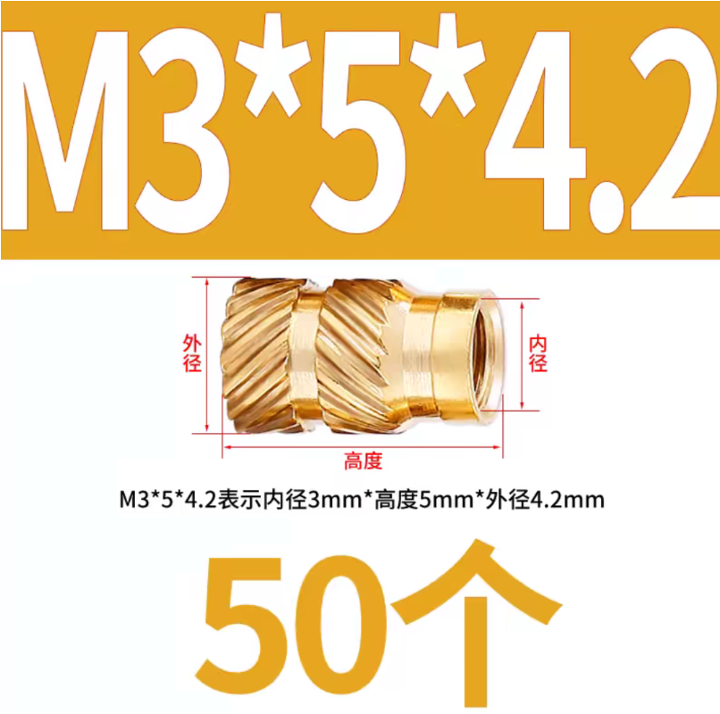
M3×5mm×4.2mm hot melt nuts, 1
Delta 6038 fan, 1

piece of activated carbon filter cotton , 1

self-locking button switch, 1

XH2.54 connecting cable, 1

anti-slip foot,

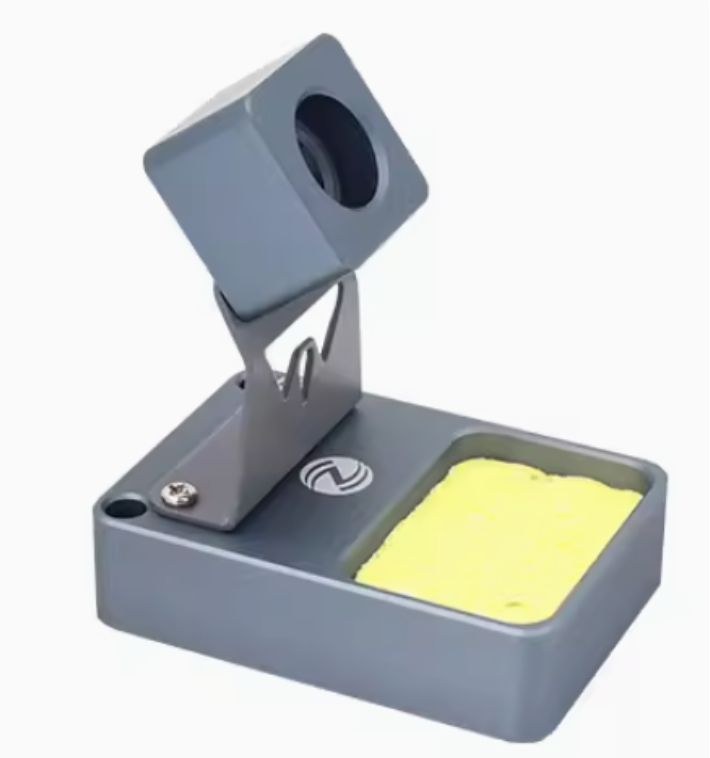
1 soldering iron stand (I used a mini soldering iron stand from Zhengdian Atom).
Assembly Method:
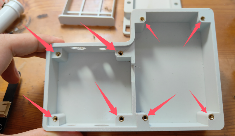
Print all 3D printed parts and use a soldering iron to press the hot melt nuts into the 12 openings.

Solder the wires to the four pins corresponding to the self-locking switch, paying attention to the positive terminal of the indicator light and the switch pin. Connect the same wire to both sides. Connect one wire to the negative terminal of the indicator light and another wire to the other side of the switch. Pass the switch wire
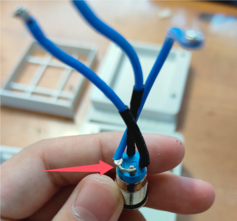
through the circular opening in the base and tighten the fixing nut

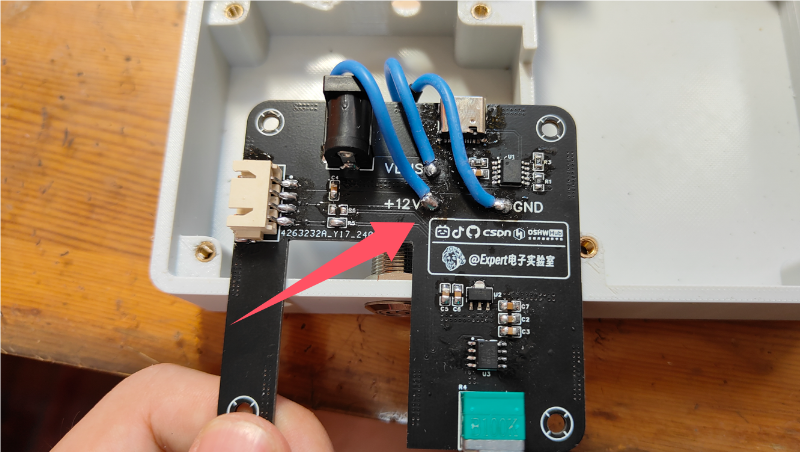
. Solder the wires on the switch to the control board. Connect the positive terminal of the indicator light to +12V and the negative terminal of the indicator light to GND. Connect the wire on the other side of the switch to VBUS. After soldering, place the control board into the base

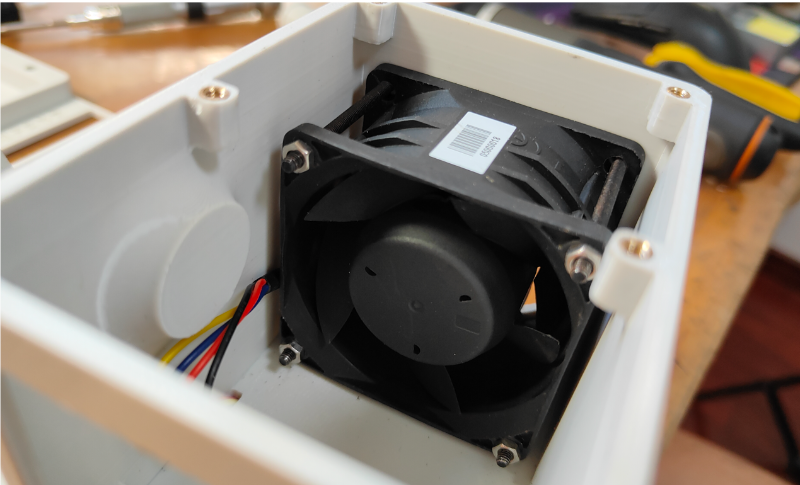
. Pass the four wires of the fan through the small opening in the top cover and connect them to the XH2.54 ribbon cable. Note the connection sequence (red for power, black for ground, blue for PWM signal, yellow can be left unconnected). After connection, plug the XH2.54 ribbon cable into the control board


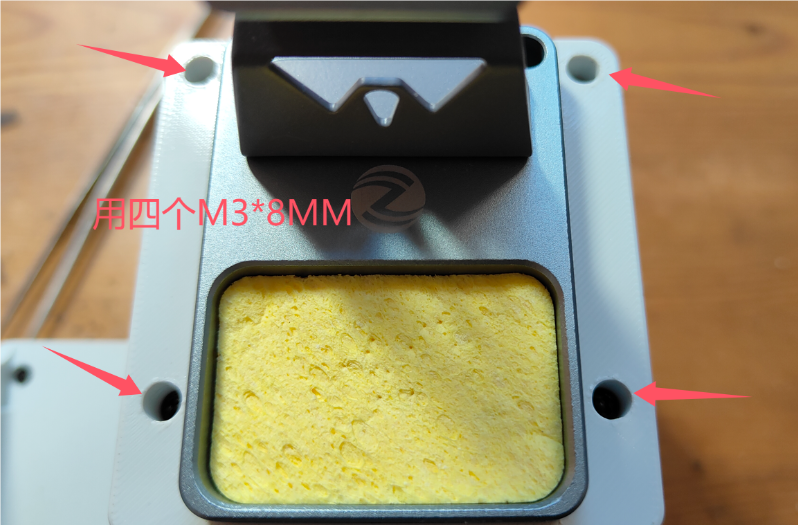
. Tighten the eight screws on the top cover.
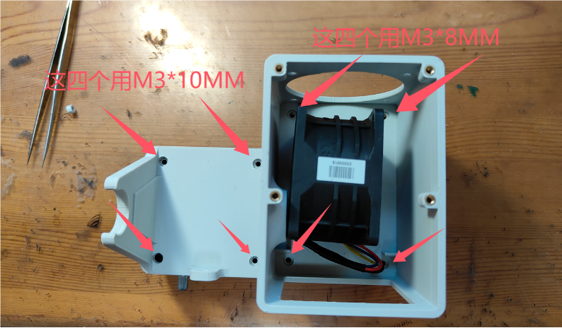

Tighten the four screws and nuts on the fan.


8. Fix the soldering iron stand to the top cover (using double-sided tape or glue).
Tighten the four screws on the top cover.
Place the filter sponge into the filter pin and insert it into the machine. Insert

the solder wire holder.

Install the potentiometer knob and feet.


Installation complete.

Precautions:
Please be sure to assemble according to the assembly sequence given in the instructions, otherwise, installation may not be possible.
Please use a charger that supports PD/QC fast charging protocol, otherwise, high voltage may not be induced.
The fan speed is very fast, please pay attention to safety when using it, do not touch the fan blades with your hands.
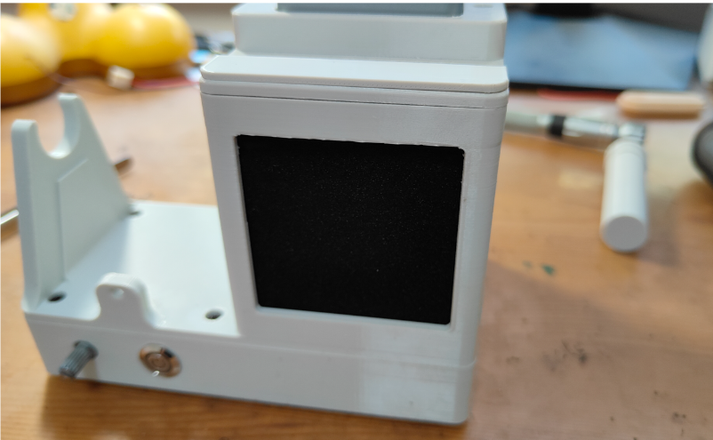
Please use a high-density filter to ensure the solder fume filtration effect.
Please use an FDM printer to print, which can facilitate the installation of the hot melt nut.
When soldering, pay attention to the wiring of the switch pins and the correspondence of the PCB board solder points.
STM32 development board compatible with Jiangsu University of Science and Technology
To efficiently learn STM32 development, the pinout was referenced from the Jiangsu University of Science and Technology video tutorials, avoiding manual wiring. Based on actual needs, a CH340C was added for serial communication, along with the W25Q64 (FLASH chip) and TJA1050 (CAN communication) from the latest video content.
PDF_STM32 Development Board Compatible with Jiangsu University of Science and Technology.zip
Altium_STM32 development board compatible with Jiangsu University of Science and Technology.zip
PADS_STM32 development board compatible with Jiangsu University of Science and Technology.zip
BOM_STM32 Development Board Compatible with Jiangsu University of Science and Technology.xlsx
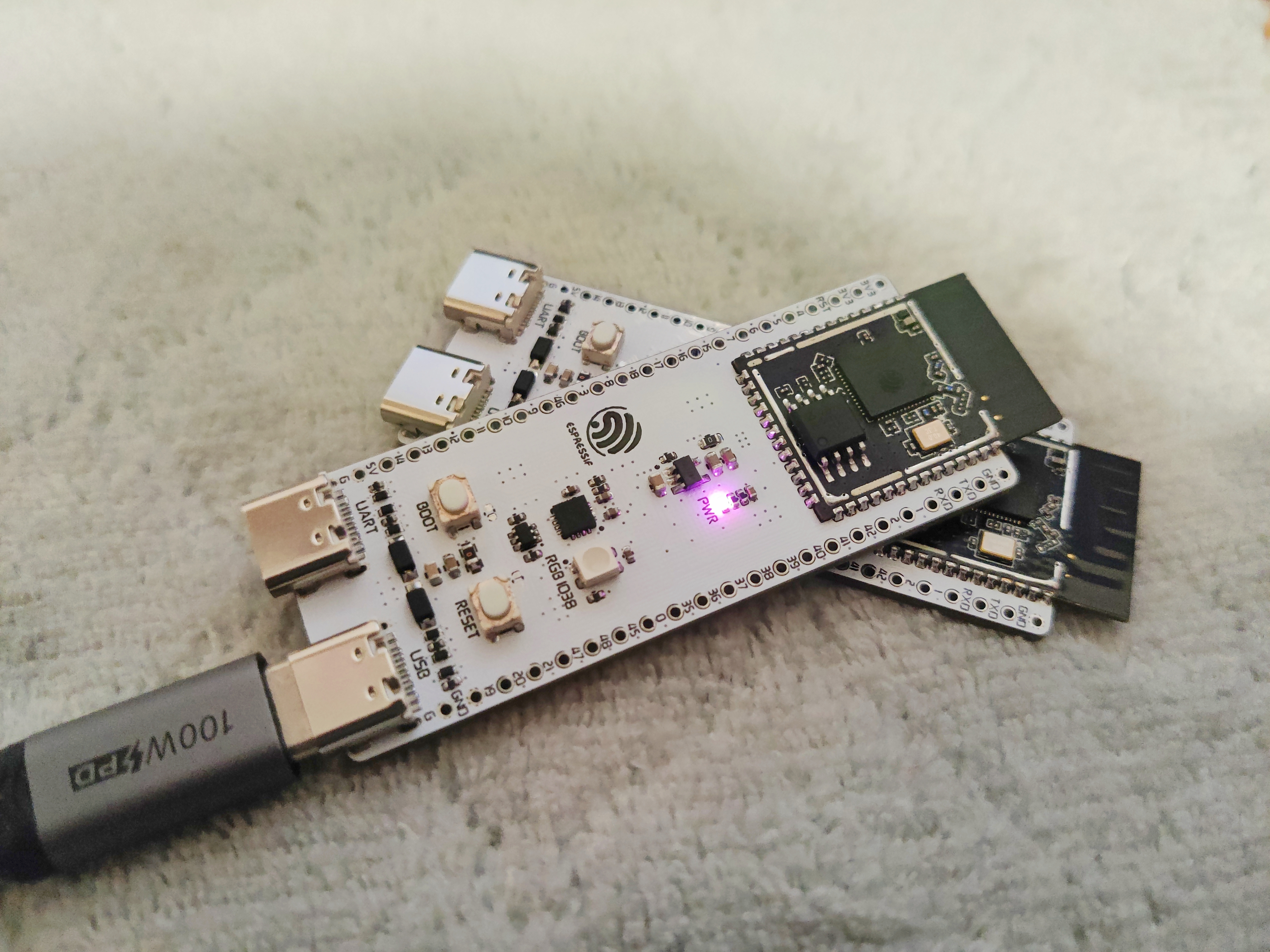
Refer to the Espressif ESP32-S3-DevKitC-1 development board introduction:
https://docs.espressif.com/projects/esp-idf/zh_CN/stable/esp32s3/hw-reference/esp32s3/user-guide-devkitc-1.html
![ESP32-S3_DevKitC-1_pinlayout_v1.1.jpg]

![IMG_20240802_230108 - copy.jpg]
![IMG_20240802_225900 - copy.jpg]

PDF_ESP32-S3-DevKitC-1.zip
Altium_ESP32-S3-DevKitC-1.zip
PADS_ESP32-S3-DevKitC-1.zip
BOM_ESP32-S3-DevKitC-1.xlsx
93324
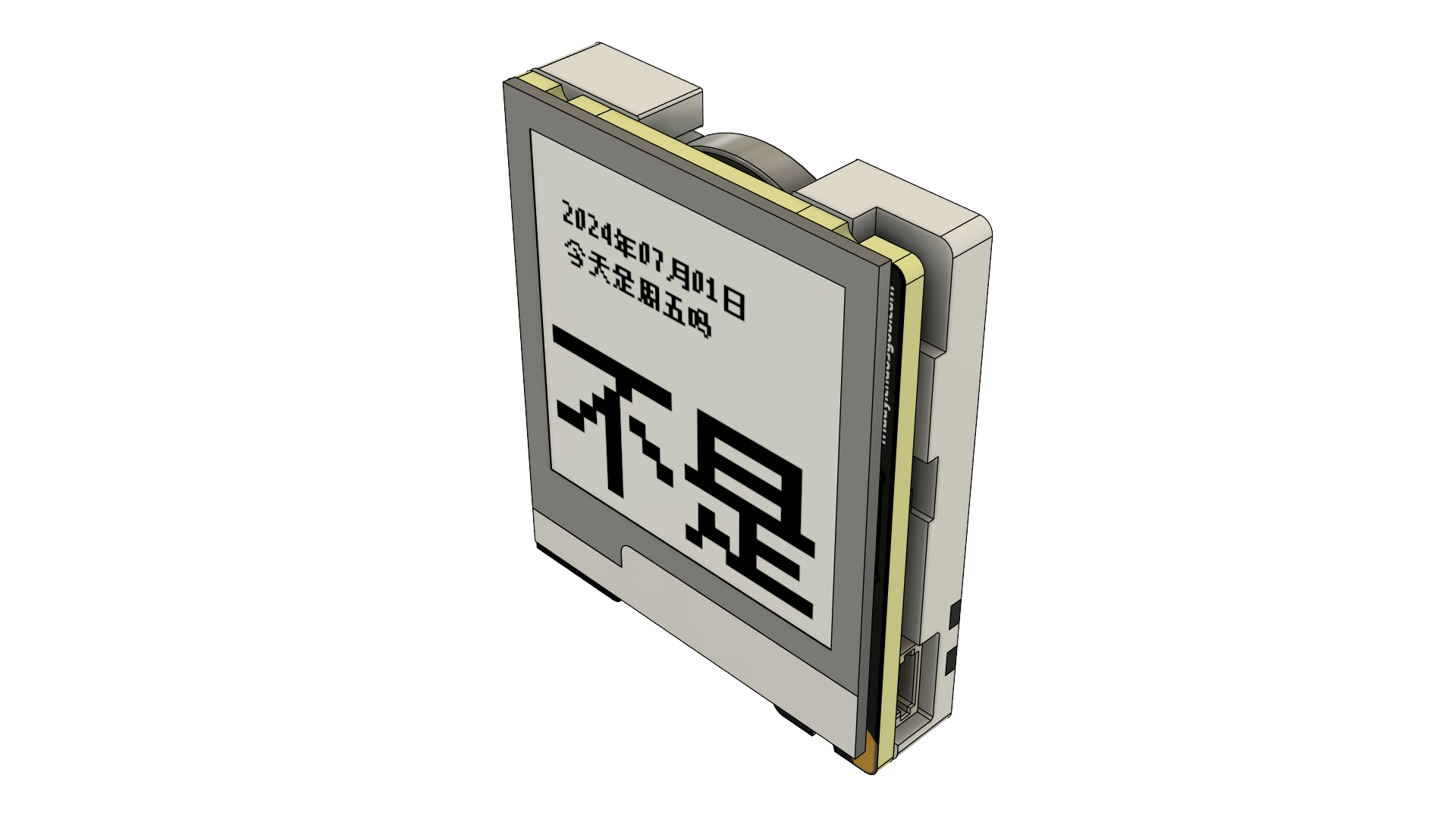
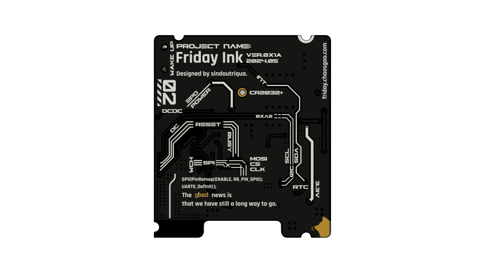
This is Friday Ink, an e-ink calendar with Friday detection.
An e-ink calendar powered by a coin cell battery, but without much battery anxiety.
Is today Friday?
(Bilibili video introduction)
GitHub project address
MakerWorld address
Top
Bottom
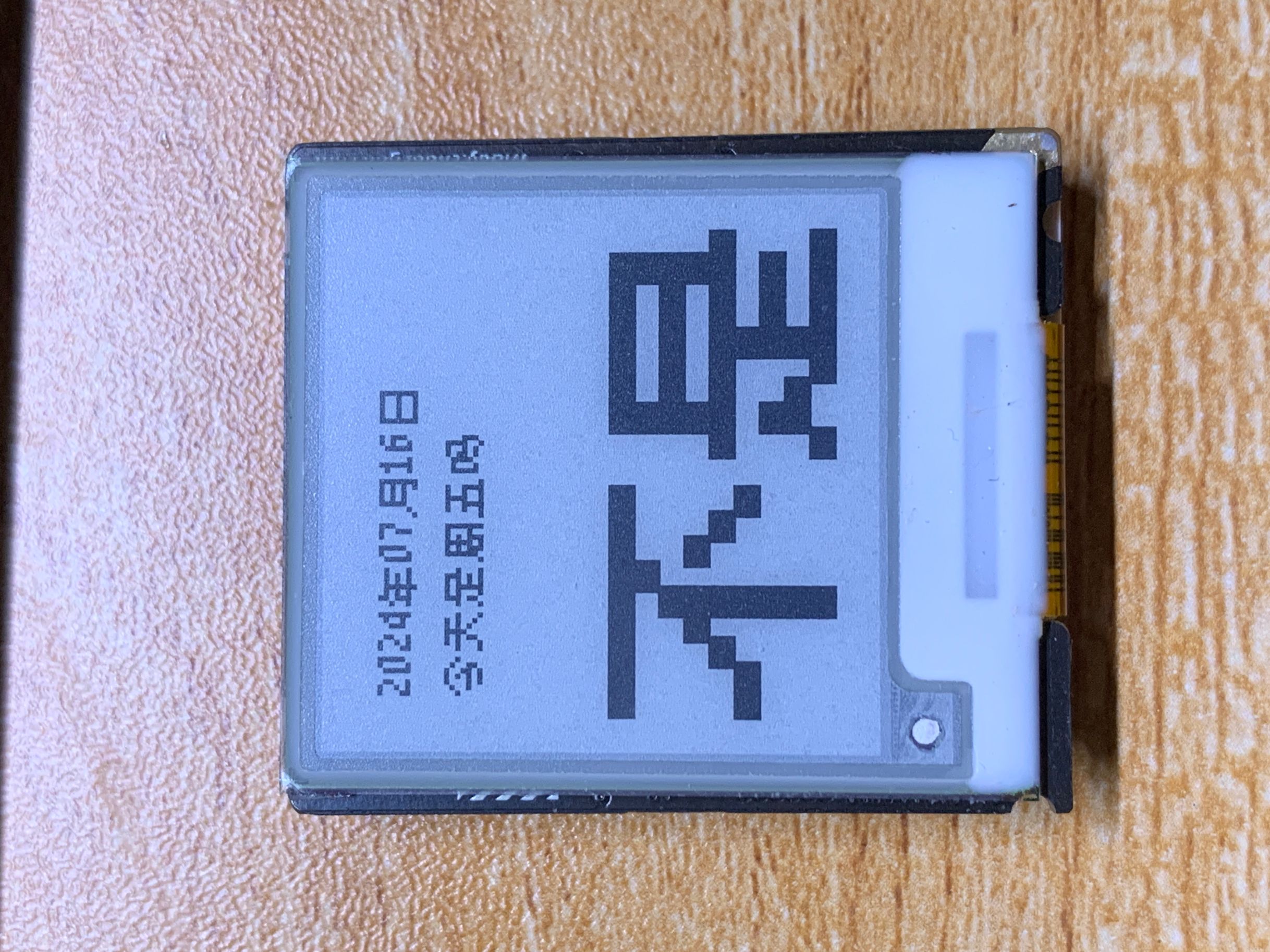
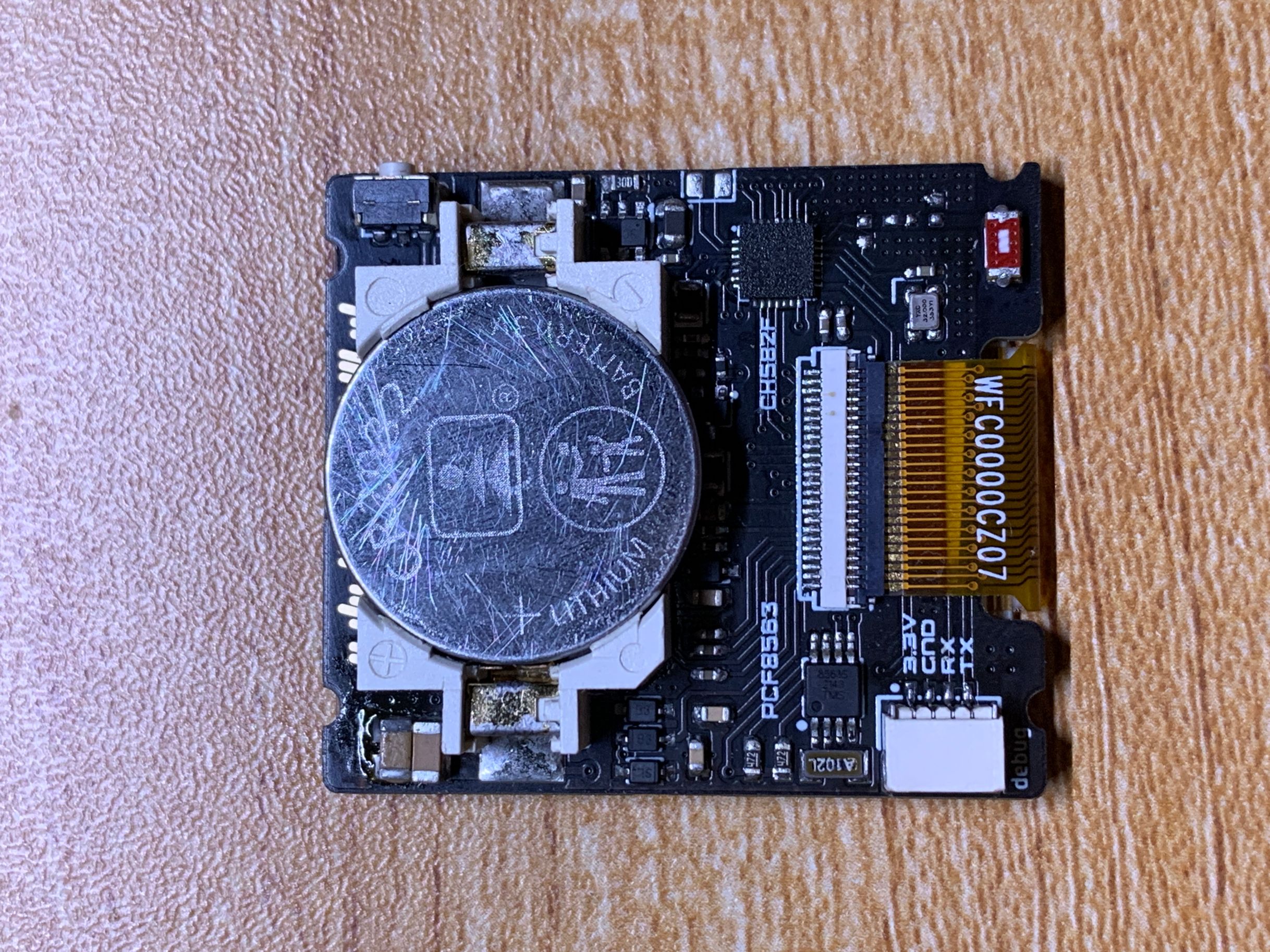
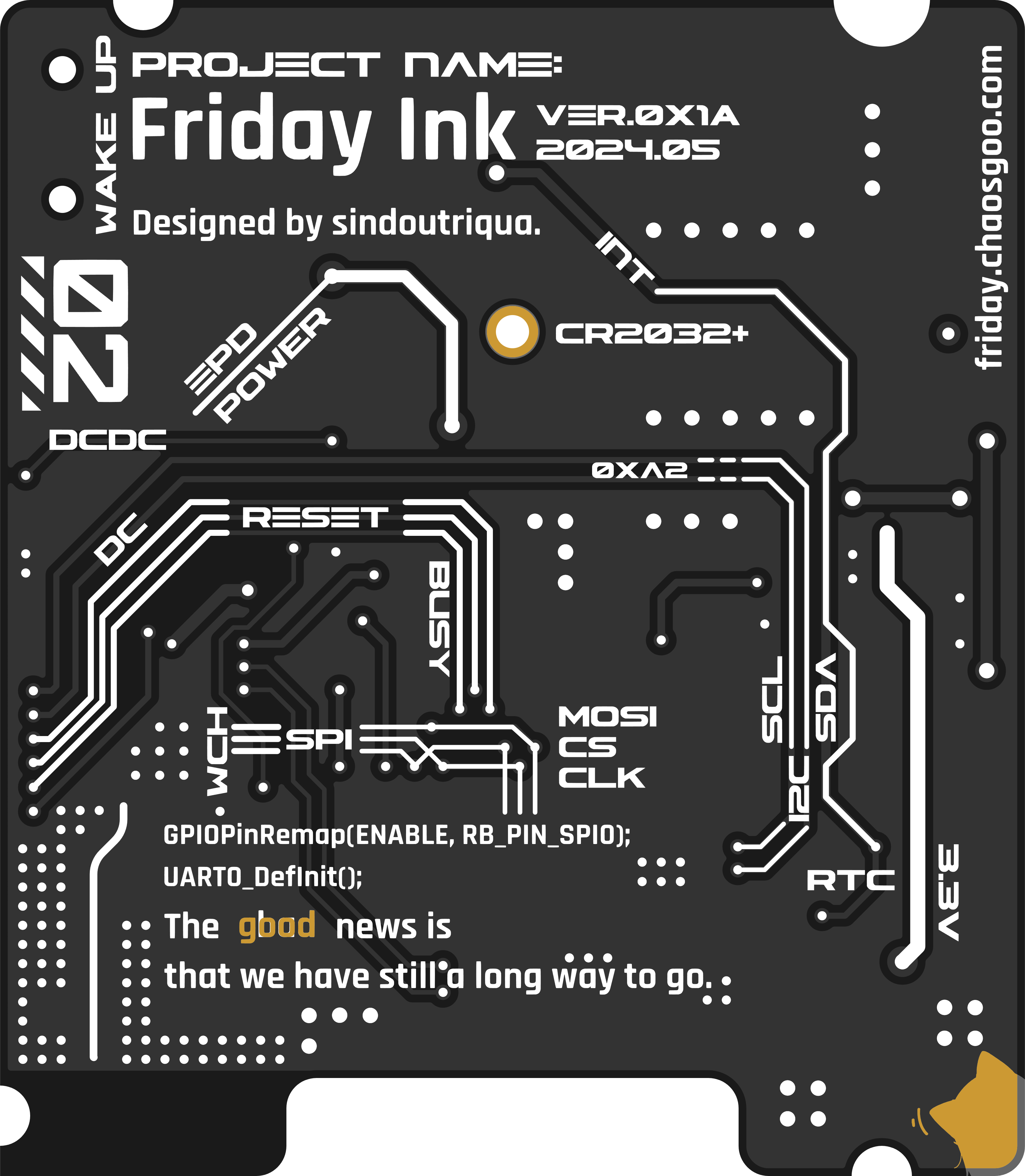
This is a device that uses CH582F as the main controller, an e-ink screen as the display medium, and is powered by a CR2032 button battery.
Essentially a calendar, but with the addition of Friday detection, it becomes a Friday detector.
Inspired by the iOS widget of the Jike App.
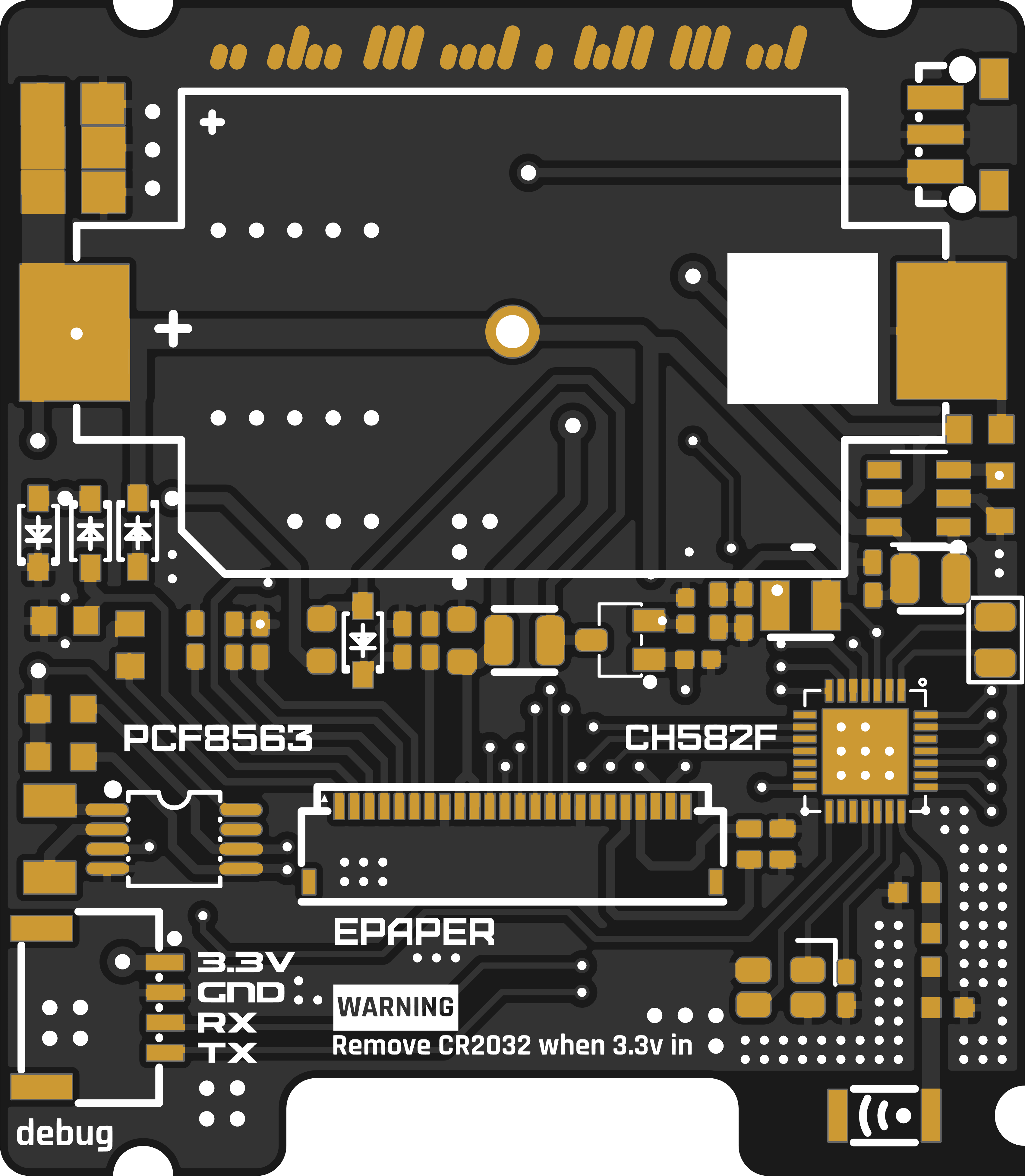
PCB Preview
Top
Bottom
Basic Parameters
Hardware Parameters
Main Controller CH582F 32KB RAM + 448KB Flash
Clock Chip PCF8563T
Screen 1.54-inch e-ink screen SSD1607
DC-DC Chip SGM6603-3.3YN6G
Power Supply CR2032 Battery
Note:
When using the SSD1607 screen driver IC, an SGM6603 needs to be soldered, as the SGM6603 is needed to completely disconnect the e-ink screen power supply.
I picked up this screen from Xianyu (a second-hand marketplace). After buying it, I found that it had the same silkscreen as a 9.9 RMB Hezhou e-ink screen, and the driver IC was also the same.
In actual use, the power consumption in sleep mode never decreased. So, in a fit of anger, I added a DC-DC converter to manage the power supply of the e-ink screen. This effectively reduced its sleep current from 70μA to 3μA.
When using the SSD1681 screen driver IC, there's no need to solder the SGM6603. In this case, a 0-ohm resistor is used to short-circuit pins 5 and 6 of the SGM6603, and there's no need to solder the 4.7μH inductor below the SGM6603.
This is currently the black and white dual-color e-ink screen sold by Zhongjingyuan. The display effect is much better than the one I bought on Xianyu. Although the resolution is the same (200x200), the effect is clearer and the contrast is better. The downside is that it's more expensive than the one I bought for 5 yuan on Xianyu.
Because it can sleep normally, a DC-DC converter is no longer needed, and the power consumption is slightly better than the SSD1607 version.
Dimensions:
34mm × 39mm × 8mm.
Power consumption information:
Sleep state ≈ 3μA;
Refresh 10~20mA, immediately enters sleep mode after refresh.
Calibration instructions:
Press and hold the button during power-on. Enter time synchronization mode, and release the button after seeing the image below.
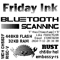
The device will then search for nearby Bluetooth broadcasts. It will automatically restart when a time broadcast matching the agreed-upon format is found.
The time broadcast format is 'F' + a hexadecimal string of the timestamp + 'R'. You can use a small program called Friday Ink Time Synchronization for time synchronization.

If no matching time broadcast is found within 20 seconds of entering time synchronization mode, it will automatically exit synchronization. It is recommended
to compile and flash the firmware
in a Linux environment. Here, I am using the Ubuntu subsystem within WSL2.
Clone this project, cd into it, and execute `git submodule update --init --recursive`
to install Rust
. Follow the Release interface of the riscv-gnu-toolchain repository to download riscv32-elf-ubuntu-22.04-gcc-nightly, configure the environment variables
according to your MRS_Community, and modify the header file directory in `u8g2_rs`.
Modify the screen creation parameters in `main.rs` according to the screen type. Execute `
cargo`. The `build-hex` command obtains a pre-compiled hex file.
Using WCHISPStudio in serial mode, the hex file is downloaded.
Q

&A
: Q: What to do if time calibration gets stuck on the calibration page?
A: It's recommended to send a time broadcast beforehand to ensure the phone and device are close enough. Then, the device enters calibration. If it fails to automatically exit calibration after 20 seconds or the button cannot force exit calibration, remove and reinstall the battery.
Known issue:
Time calibration has a certain probability of getting stuck on the calibration page .
Consider introducing a watchdog timer. The watchdog timeout resets
the FPC socket HC-FPC-05-09-24RLTAG. This socket model is different from the one I bought on Taobao, but the contact is more reliable. The trade-off is that the e-ink screen ribbon cable extends beyond the PCB area.
References:
ch58x-hal
CH582F schematic; azunya's button battery Bluetooth thermometer CR1220+CH592F+SHT40.
The SSD1681 driver comes from pigot's U8g2_Arduino
update log.
August 3, 2024:
Added SSD1681 compatibility
information, supplementary Q&A, and references.
PDF_This is Friday Ink, an e-ink screen calendar with Friday detection..zip
Altium_This is Friday Ink, an e-ink calendar with Friday detection..zip
PADS_This is Friday Ink, an e-ink calendar with Friday detection..zip
BOM_This is Friday Ink, an e-ink screen calendar with Friday detection..xlsx
93327
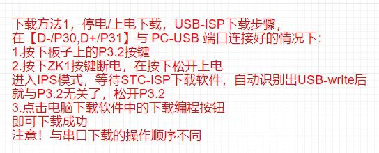
STC32 Development Board
The STC32G12K128 development board integrates many commonly used peripherals in learning.
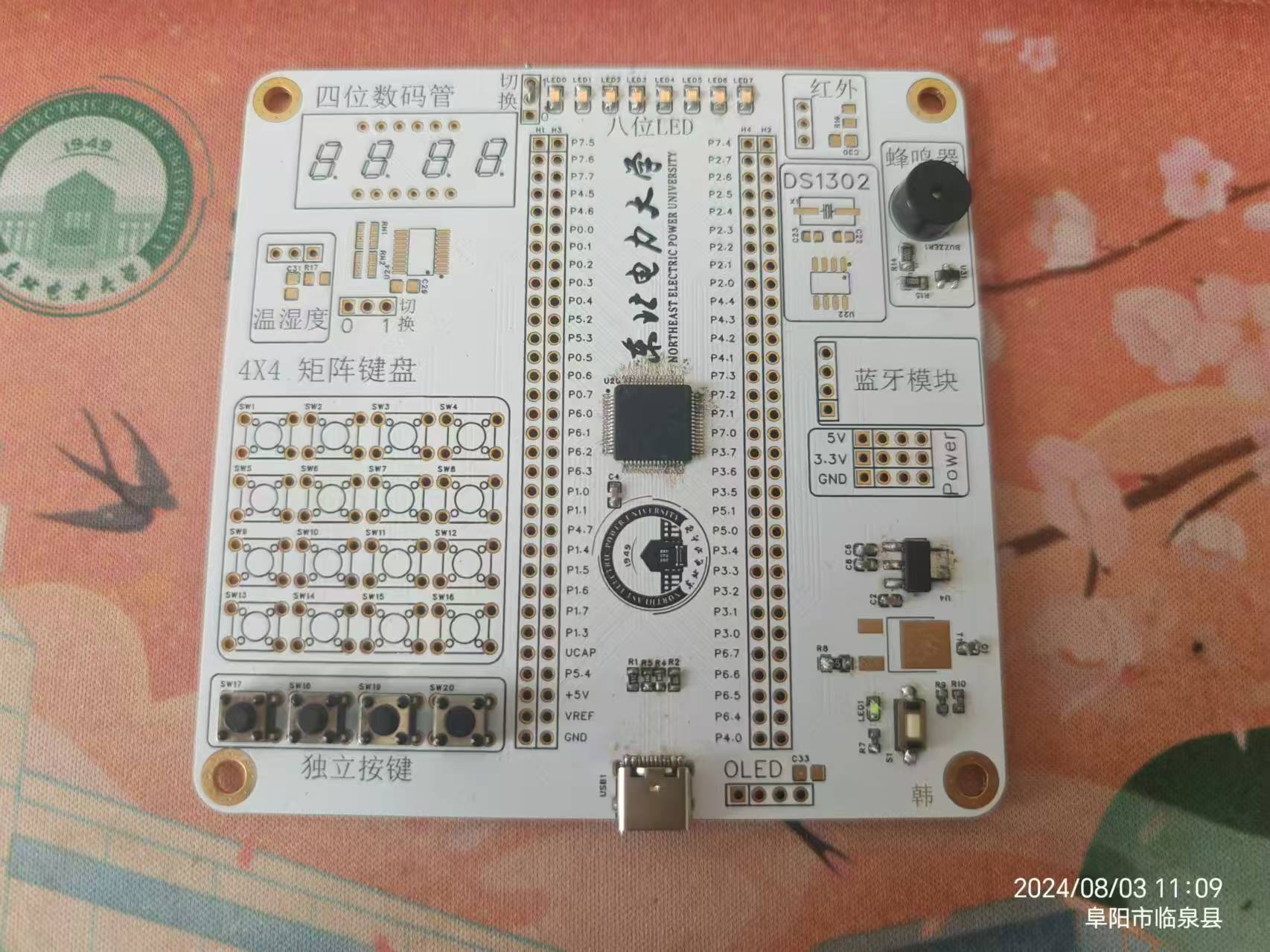
The STC32 development board only has individual buttons and LED running lights soldered on. Testing showed all functions work correctly. It references the official STC "Dragon Slayer" development board. Having recently learned the classic 51 microcontroller, I added matrix buttons, temperature and humidity control, DS1302 clock, infrared, digital tube display, and Bluetooth functionality, referencing the Puzhong 51 development board.
The power supply section has 5V and 3.3V, with all pins brought out .
For program upload,
simply connect to the computer via USB and use the official STCsip software to download the program, as shown in the image below.
Simple running light test:
WeChat_20240803125518.mp4
PDF_STC32 development board.zip
Altium_STC32 development board.zip
PADS_STC32 development board.zip
BOM_STC32 development board.xlsx
93328
Colorful Flowing Lights_LED-5050RGB
This project utilizes 5050RGB tri-color LEDs and auxiliary components to achieve a colorful running light function. It can be used for microcontroller learning, offering diverse color combinations and allowing for various color displays by utilizing the brightness ratios of the three colors.
Due to the limited I/O driving capabilities of the microcontroller, transistors are used for driving.

Circuit board images,
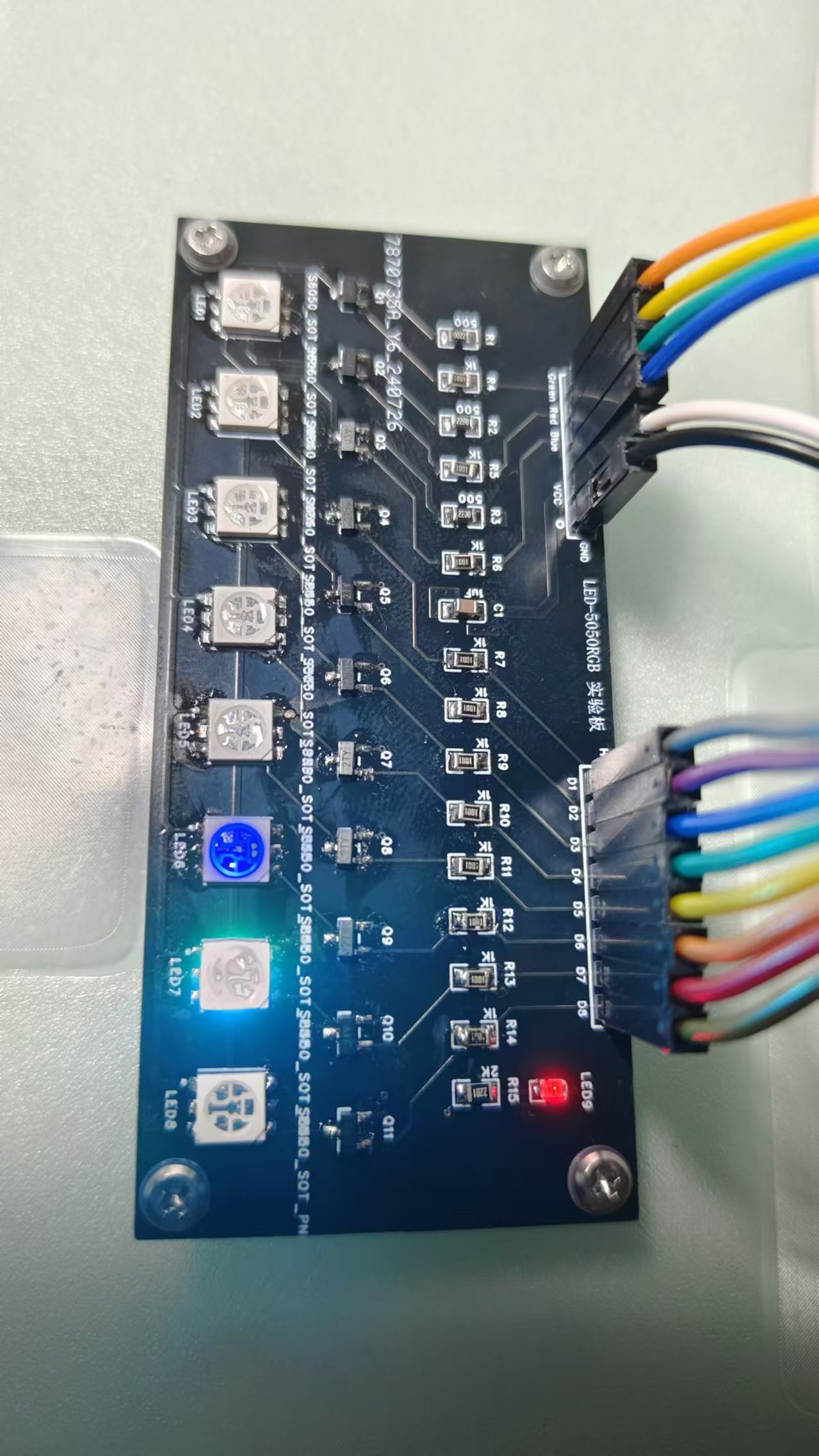
finished product images
Marquee video.mp4
RGB LED Display Program_5050RGB_V3.rar
PDF_Colorful Flowing Lights_LED-5050RGB.zip
Altium_Colorful Flowing Lights_LED-5050RGB.zip
PADS_Colorful Flowing Lights_LED-5050RGB.zip
BOM_Colorful Flowing Lights_LED-5050RGB.xlsx
93330
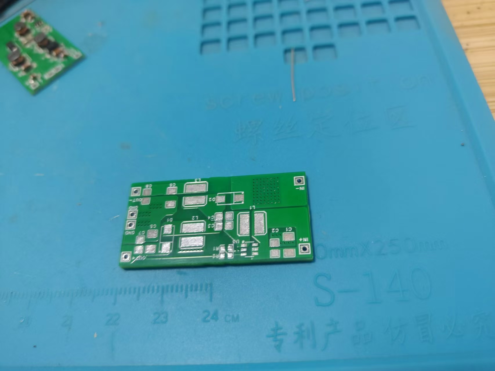
SX1308 Fixed 5V Positive and Negative Voltage Module
The SX1308 positive and negative power supply module has a fixed 5V voltage, is inexpensive, and is easy to replicate.
The SX1308 fixed 5V positive and negative voltage module allows voltage modification by adjusting resistors R1 and R2. SEPIC boost converter with CUK inverted output.
PDF_SX1308 Fixed 5V Positive and Negative Voltage Module.zip
Altium_SX1308 Fixed 5V Positive and Negative Voltage Module.zip
PADS_SX1308 Fixed 5V Positive and Negative Voltage Module.zip
BOM_SX1308 Fixed 5V Positive and Negative Voltage Module.xlsx
93331
Temperature and humidity detection
It measures temperature, humidity, and battery level, and operates with low power consumption.
The hardware design was inspired by competition videos. The entire development process, from circuit diagram design to PCB layout, followed the learning videos. The software drivers referenced the provided code, while the application was modified to support displaying voltage, temperature, and humidity, and can be woken up by a button. After waking up, the display can be switched between temperature/humidity and battery level via a button. I personally tested it for three or four days, and the battery consumption was normal. Overall power consumption is sufficient for use. Videos are available for reference. The code is attached, but its bug-free nature is not guaranteed. It has been running normally after several days of testing.
VID_20240803_191716.mp4
TH.zip
PDF_Temperature and Humidity Detection.zip
Altium_Temperature and Humidity Detection.zip
PADS_Temperature and Humidity Detection.zip
BOM_Temperature and Humidity Monitoring.xlsx
93332
220V-12V-30W standard power supply
220V-12V-30W standard power supply, dual output
220V-12V-30W standard power supply, dual outputs: one direct output and one fixed 12V or adjustable output. Discussion and guidance are welcome. (Only group: 289917684)
3ded5f8f80c9965eacdd7c670ffb184.jpg
5e89eabc5d6abe379e6ca7b21c711c2.jpg
473412c24319667580c4fc11607b47c.jpg
PDF_220V-12V-30W Standard Power Supply.zip
Altium_220V-12V-30W Standard Power Supply.zip
PADS_220V-12V-30W Standard Power Supply.zip
BOM_220V-12V-30W General Power Supply.xlsx
93333
electronic


 京公网安备 11010802033920号

 1510145UG3


