* 1. Project Function Introduction
, Design Background, and Practical Scenarios
Design Background:
Indoor temperature and humidity are crucial factors affecting human comfort and health. Therefore, designing a desktop temperature and humidity monitor can help users monitor and control the comfort of the indoor environment in real time. People are paying increasing attention to indoor air quality, especially in enclosed spaces such as offices and homes. Obtaining accurate temperature and humidity data through monitoring instruments helps optimize indoor air quality. In academic research, a desktop temperature and humidity monitor can serve as an experimental tool for collecting and analyzing indoor environmental data to study the impact of temperature and humidity changes on human health and productivity. In engineering applications, this device can be used in product development, quality control, and other fields to ensure the stability and reliability of products under various environmental conditions.
Practical Scenarios :
A low-power desktop temperature and humidity monitor based on the STM32G030K6T6 chip can be used in various practical scenarios in daily life and can solve some common problems.
1. Indoor Environment Monitoring: Real-time monitoring of indoor temperature changes helps users adjust air conditioners, heaters, and other equipment to improve indoor comfort. Monitoring indoor humidity levels helps prevent the effects of excessive humidity or dryness on furniture, wooden products, or electronic equipment.
2. Health and Comfort Optimization: Temperature and humidity monitors help users monitor air quality, ensuring the indoor environment meets health standards and helping to reduce allergic reactions or respiratory problems. Maintaining suitable temperature and humidity helps improve sleep quality, especially important for nurseries or people requiring special conditions.
3. Property Protection: By monitoring indoor humidity, it prevents wooden products from molding or swelling due to excessive humidity, and also prevents electronic devices from being damaged by excessively low humidity. Furthermore, a stable temperature and humidity environment can extend the lifespan and maintain the good condition of valuable artworks, books, or archives.
4. Energy Saving and Cost Reduction: Air conditioning and heating control, adjusting the operating time and settings of indoor air conditioners and heaters based on temperature and humidity data, can save energy costs.
5. Early Warning Functions: Alarms can be set to remind users when the temperature or humidity exceeds preset ranges, preventing adverse environmental conditions from affecting health or belongings.
*2. Project Attributes:
This project is being publicly disclosed for the first time. It has not participated in any competitions, received any awards, or undergone any presentations at school.
* 3. Open Source License
: GPL 3.0 open source license
4. Hardware Part: Power Supply Circuit
Design:
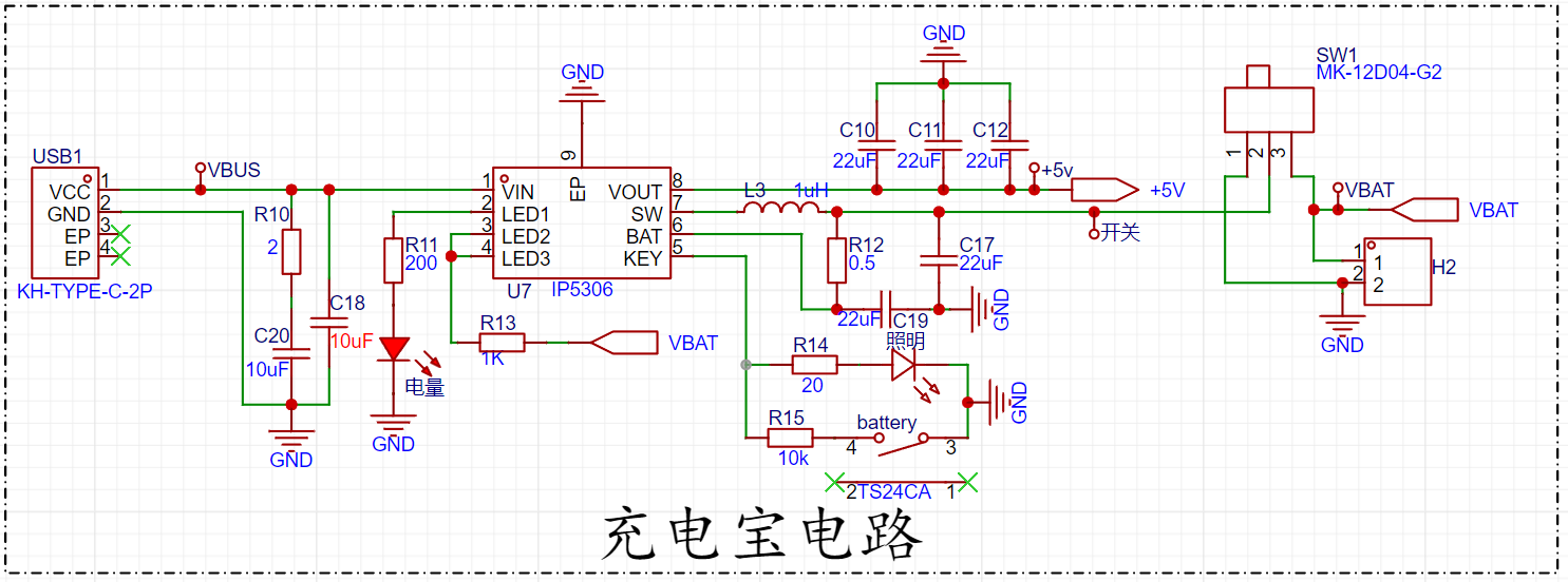
The mind map of the power supply circuit is shown below.

My design idea is to use an IP5306 chip to charge the lithium battery. This chip has high charging efficiency, outputting up to 2A of current during charging. This not only improves charging efficiency but also reduces charging time. Furthermore, when powered by a lithium battery, the IP5306 chip can automatically boost the voltage to 5V, and the ripple of the 5V output voltage is relatively small. Compared to two 1.5V dry cell batteries, which require frequent battery replacements and cause pollution from discarded batteries, this solution is not only highly efficient but also environmentally friendly and energy-saving.
IP5306 Power Management Circuit:
The IP5306 is a multi-functional power management SOC integrating a boost converter, lithium battery charging management, and battery level indicator. The IP5306's synchronous boost system provides a maximum output current of 2.4A with a conversion efficiency of up to 92%. When unloaded, it automatically enters sleep mode, with the quiescent current dropping to 100uA. The IP5306 employs switching charging technology, providing a maximum current of 2.1A and a charging efficiency of up to 91%. Built-in IC intelligently adjusts the charging current based on temperature and input voltage. It features synchronous switching charge/discharge with 2.4A synchronous boost conversion and 2.1A synchronous switching charging, achieving a boost efficiency of up to 92% and a charging efficiency of up to 91%. Built-in power path management supports simultaneous charging and discharging, adaptive charging current adjustment, and adapter compatibility with 4.20/4.30/4.35/4.40V batteries.
The following is the datasheet for the IP5306 chip:

The datasheet states that the chip has a built-in light driver, automatically detects when a phone is inserted or removed; it has low power consumption, intelligently identifies the load, and automatically enters standby mode (standby power consumption less than 100 µA); it has a built-in power MOSFET, uses a single inductor for charging and discharging, and offers multiple protections and high reliability: output overcurrent, overvoltage, and short-circuit protection; input overvoltage, overcharge, over-discharge, and overcurrent discharge protection; overall over-temperature protection; ESD 4KV; instantaneous withstand voltage 12V. As a chip integrating battery management and power management functions, the IP5306 features high-efficiency DC-DC conversion and flexible, controllable charging current characteristics, making it suitable for various portable devices and embedded systems. It can effectively optimize power management and battery usage experience.
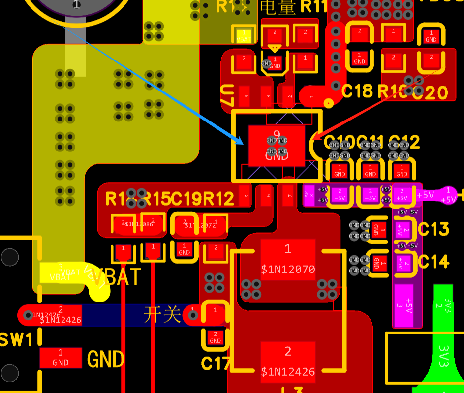
Layout considerations: The peripheral circuitry of the power management chip should be placed close to the chip, preferably using a filler approach to maximize overload current and avoid overheating due to thin traces. Use a one-piece molded power inductor with the lowest possible on-resistance and the highest possible saturation current.
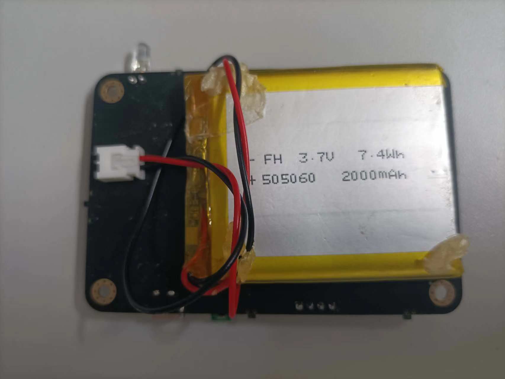
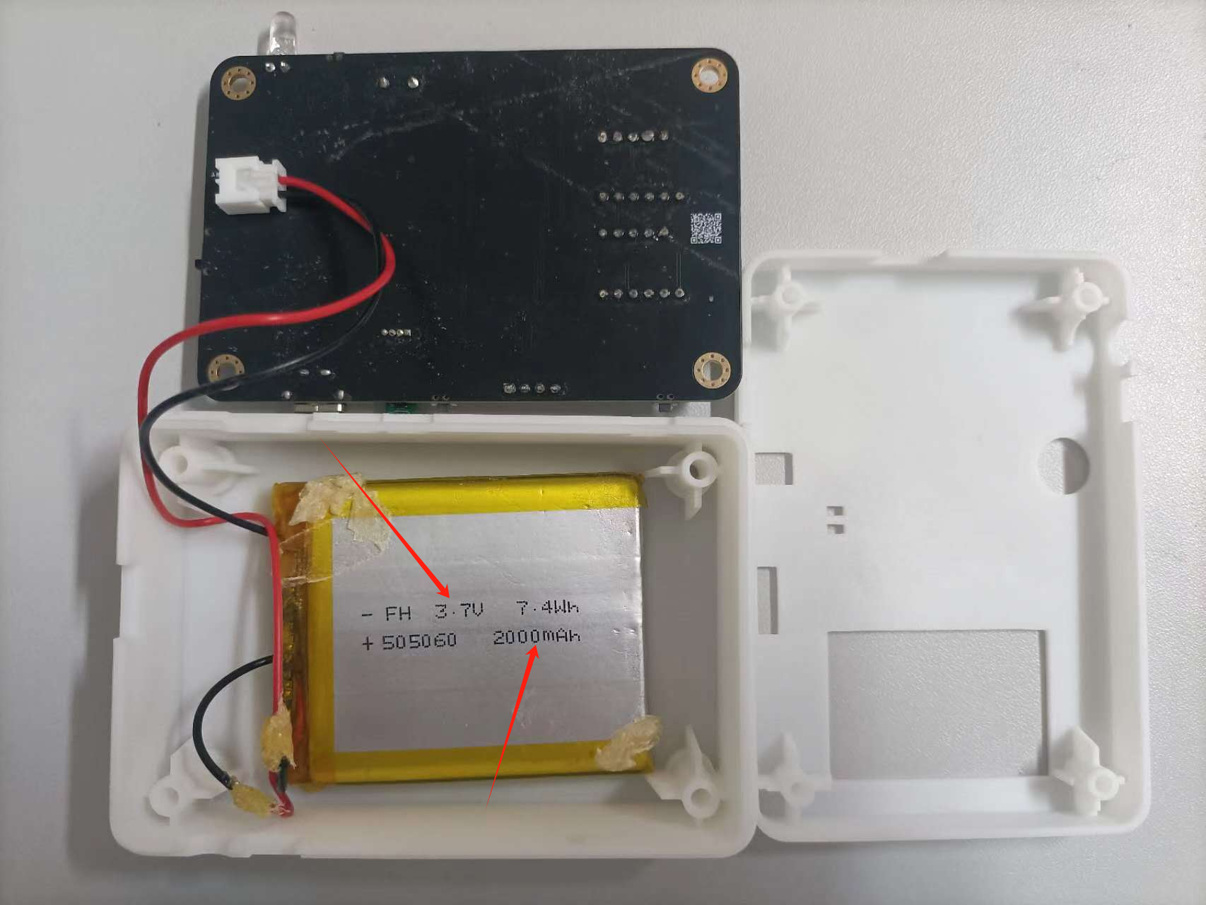
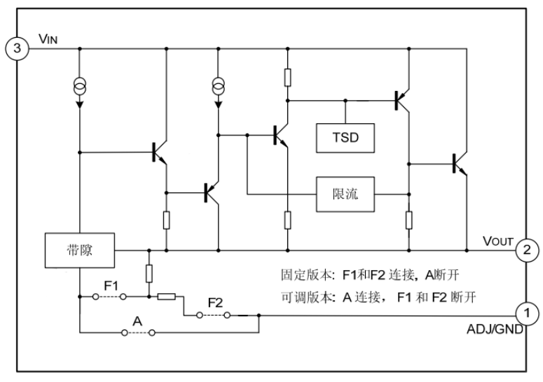
The actual battery power supply diagram on the circuit board is shown above, using a 4.7V, 2000mAh lithium battery. The AMS117 is a low-dropout linear regulator (LDO) used to provide a stable voltage output. Its operating principle is as follows:
The AMS117's input is connected to the power supply input, and it can accept a relatively high voltage from the power supply, typically between 3V and 12V. This input voltage can have some fluctuation and noise. The AMS117 has an internal reference voltage source (typically 1.2V), which is used to compare and stabilize the output voltage. This reference voltage source is crucial for ensuring the stability of the output voltage. Voltage Regulator: When the input voltage is stable, the AMS117 controls the output voltage through its internal voltage regulator circuitry (usually based on a current source and current mirror design). The output voltage magnitude is determined by the AMS117 model number; for example, AMS117-3.3 indicates an output voltage of 3.3V. Feedback Loop: A voltage divider or resistor network is placed at the output terminal to feed a portion of the output voltage back to the feedback pin of the AMS117. The AMS117 regulates its output by comparing the feedback voltage (compared to a 1.2V reference voltage source) with an internal reference voltage. Stable Output: The AMS117 adjusts its internal current source based on the feedback voltage to maintain a constant output voltage. It can handle variations in input voltage and remains as stable as possible when the output current changes. Protection Functions: The AMS117 typically features thermal shutdown and short-circuit protection to prevent damage from overload or overheating. These protection functions increase its reliability and safety in practical applications. Overall, the AMS117, through its internal feedback mechanism and voltage regulation circuitry, generates a stable, lower output voltage from a higher input voltage for stable operation of electronic devices. Layout Considerations: Generally, filter capacitors should be placed close to the PCB. Appropriate filter capacitors need to be added to both the input and output terminals of the AMS117 regulator to reduce noise and fluctuations on the power lines and ensure stable operation. Specifically, the selection of filter capacitors mainly depends on the following factors : Input filter capacitor (C_IN): Input filter capacitors are typically used to filter out high-frequency noise on the input power line, preventing this noise from propagating to the input of the regulator. It is generally recommended to use ceramic or aluminum electrolytic capacitors with capacitance values between 10μF and 100μF, and it is necessary to ensure that their voltage rating covers the input voltage range.


Output Filter Capacitor (C_OUT): The output filter capacitor is mainly used to reduce output ripple and provide a stable output voltage. It is recommended to use a small-value ceramic capacitor (e.g., 1μF to 10μF) as the output capacitor, plus a larger-value electrolytic capacitor (e.g., 10μF to 100μF) to meet filtering requirements at different frequencies.
Capacitor Type Selection: When selecting filter capacitors, ceramic capacitors have fast response and low ESR (equivalent series resistance), making them suitable for filtering high-frequency noise; while electrolytic capacitors have large capacitance, making them suitable for filtering low-frequency noise. In practical designs, these two types of capacitors are often used in combination to achieve better filtering results.
Microcontroller Main
Control Circuit: The microcontroller plays a core control and processing role in the circuit. It processes input signals, executes specific algorithms or logic, and then generates corresponding outputs. These input signals can come from sensors, other electronic devices, or user interfaces, and the outputs can control actuators, display information, etc. In complex electronic systems, the microcontroller typically coordinates communication and collaboration between different components. It can communicate with other peripheral devices (such as memory, sensors, actuators, etc.) via bus protocols (such as I2C, SPI, etc.). The main control microcontroller can execute specific operations according to the programmed logic. These operations can be based on pre-set algorithms, conditional judgments, timing control, etc., to realize complex system functions. The main control microcontroller is usually responsible for interacting with the user interface, such as inputting and outputting information through buttons, displays, LED indicators, etc., to provide a better user experience.
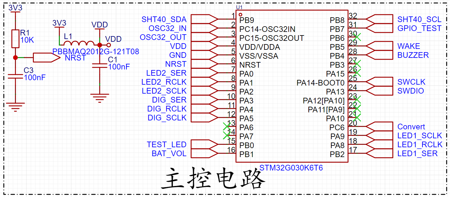
It is important to note that the 3V3 voltage should ideally be filtered through a ferrite bead before entering the microcontroller. Ferrite beads can be used as electromagnetic interference (EMI) filters in circuits. They are usually placed on signal lines or power lines to suppress the propagation of high-frequency noise and interference signals, thereby ensuring signal quality and stability.

In communication lines, especially in Ethernet and telecommunications fields, ferrite beads are often used for data line isolation. They help block potential ground loops or common-mode noise, improving the reliability and anti-interference capability of data transmission. In some cases, ferrite beads can also be used to adjust the impedance of signal lines to ensure signal transmission matching and optimal performance. For some applications, ferrite beads can also provide overcurrent and overvoltage protection by limiting current and preventing equipment damage through their inductive characteristics. In short, ferrite beads, through their inductive and absorption characteristics, can suppress interference, improve signal quality, and protect equipment in circuits, especially in high-frequency and communication fields.
Layout Considerations:

Crystal oscillator circuit routing should use differential equal-length traces. The two matching capacitors of the crystal oscillator should be placed as close as possible to the crystal. Crystal oscillators are made of quartz crystals and are easily affected by external impacts or drops, so during layout, it is best not to place them on the PCB edge, but as close as possible to the chip. Crystal traces need to be protected with GND and kept away from sensitive signals such as RF, CLK signals, and high-speed signals. In some crystal oscillator PCB designs, adjacent layers are cleared (net), or both the same layer and adjacent layers are cleared, and the third layer needs to have a complete ground plane. This is done to maintain a constant load capacitance. The formula for calculating the crystal oscillator load capacitance is:
CL=C1*C2/(C1+C2)+Cic+Cp.
Cic is the internal capacitance of the integrated circuit, and Cp is the parasitic capacitance of the PCB board. Excessive parasitic capacitance will lead to an excessively large load capacitance, causing crystal oscillator frequency deviation. In this case, reducing the matching capacitors C1 and C2 may improve the situation.
The SHT40
temperature and humidity sensor module is used on a desktop temperature and humidity meter to detect temperature and humidity. The SHT40 uses I2C for communication. R8 and R9 on the module are pull-up resistors for I2C communication, acting as wired-AND resistors to support multiple devices.
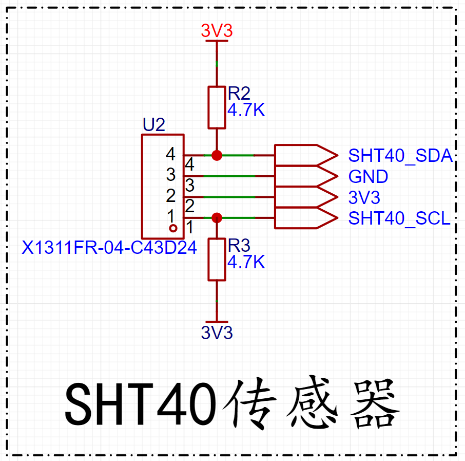
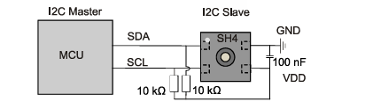
Two 10k resistors are used as pull-up resistors to release the bus and transfer control to the master when the slave device does not respond during I2C communication.
The
74HC595 is a commonly used shift register, typically used to expand the output ports of a microcontroller. The 74HC595 has three main input ports:
SER (Serial Input): Serial input, used to receive data input.
SRCLK (Shift Register Clock): The shift register clock, used to control the shifting of data bits.
RCLK (Register Clock): The register clock, used to control when the data in the shift register is output in parallel to the output port.
There is also OE (Output Enable) to control output enable.
The 74HC595 has eight parallel output ports (Q0-Q7), through which external devices or lights can be controlled.

The 74HC595's workflow is as follows:
Serial Data Input: First, the data to be output is input sequentially into the 74HC595's serial input (SER). The data can be a single bit or a sequence of multiple bits. Data Shifting: By controlling the shift register clock (SRCLK), the serially input data is shifted into the shift register bit by bit. Each time the rising edge of the SRCLK signal arrives, the data in the register shifts one bit to the left, and the new data bit enters the least significant bit (Q0) of the register from the serial input. Parallel Data Output: After all data bits are shifted into the register, the data in the register is output in parallel to eight output ports (Q0-Q7) by controlling the register clock (RCLK). At this time, the data bits in Q0 are output to the first output port, the data bits in Q1 are output to the second output port, and so on. Output Control: Output enable is controlled via OE, determining whether output is allowed on the output port.
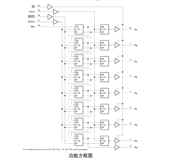
74HC595 Internal Functional Block Diagram:
74HC595 Timing Diagram:

PCB Layout Considerations:

Each VCC pin should have a good bypass capacitor to prevent power interference. For single-supply devices, 0.1μF is recommended; if there are multiple VCC pins, 0.01μF or 0.022μF is recommended for each power supply pin. Multiple bypass capacitors can be connected in parallel to suppress different noise frequencies. 0.1μF and 1μF are often used in parallel. For better results, bypass capacitors should be mounted as close as possible to the power supply pins.
An 8-segment LED display
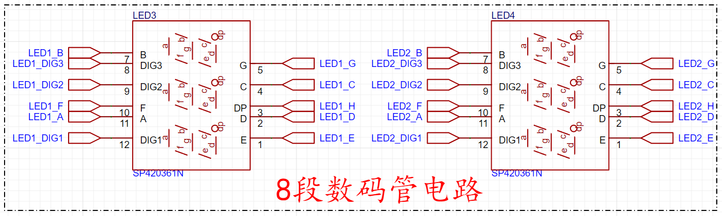
(also known as a 7-segment display) is a common digital display device. It consists of seven LED strips (or segments) and a decimal point, and can display the ten digits from 0 to 9, as well as some letters. LED Segment Arrangement: Each LED display has seven LED segments: a, b, c, d, e, f, and g, plus a decimal point dp. These segments are arranged in the shape of the number "8," and each segment can be lit independently.
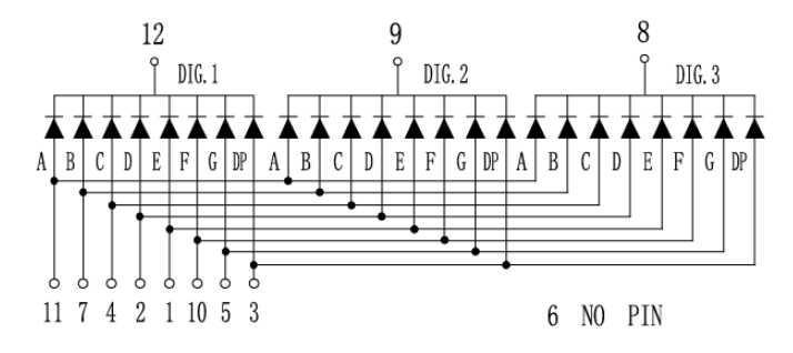
Common Anode and Common Cathode Designs: Common Anode LED Display: In a common anode LED display, all anodes are connected together, while the cathode of each LED segment is controlled individually. By energizing a specific cathode, the corresponding LED segment can be lit.
Common Cathode LED Display: In a common cathode LED display, all cathodes are connected together, while the anode of each LED segment is controlled individually. By energizing a specific anode, the corresponding LED segment can be lit.
Display of Numbers and Letters: By appropriately controlling the current of each LED segment, numbers from 0 to 9, as well as some letters, can be displayed. For example, displaying the number "0" requires lighting all segments, while displaying the number "1" only requires lighting segments b and c, and so on. Circuit driving: The circuitry of a digital display typically includes control logic and drivers. For each seven-segment display, appropriate control signals are needed to select the number or letter to be displayed and to deliver the appropriate current to the corresponding LED segment to ensure its brightness and display effect.
Multi-digit LED display: In cases of complex numerical displays, multiple LEDs are typically combined to form a multi-digit LED display. Each LED can be controlled independently, quickly switching between displaying different numbers or characters to achieve complex display tasks.
Brightness control: Some LEDs also have brightness adjustment functions, which can adjust the brightness of the LEDs by controlling the current or using PWM (Pulse Width Modulation) technology to adapt to different ambient light and display needs.
Applications: LEDs are widely used in calculators, electronic clocks, counters, dashboards, and other devices that require digital display. They convey digital information simply and effectively and are widely accepted and used.
Buzzer driver circuit:
A buzzer driver circuit is typically used to control the operation of a buzzer (or piezoelectric buzzer). A buzzer is essentially a piezoelectric device that produces sound; its working principle is based on the piezoelectric effect. Self-excited buzzers are driven by DC voltage and do not require AC signals. They only need a drive level output to the drive port, and the drive current is amplified by a transistor to produce sound.

Since buzzers typically have a large operating current, they cannot be directly driven by the microcontroller's I/O ports. Therefore, an amplifier circuit is needed. Generally, a transistor is used to amplify the current. The diagram shows an NPN transistor used for driving, with R6 acting as a pull-down resistor. When the microcontroller's GPIO port has no output, the base of the transistor is kept low, preventing it from conducting. When the transistor conducts, the current is amplified and flows through the buzzer, causing it to sound.
The diagram above shows a buzzer circuit driven by an NPN transistor. It only requires the transistor to operate in a switching state. R6 is a pull-down resistor. If the input terminal of R4 is floating, the presence of R6 ensures the transistor remains reliably off. Without R6, when the BUZZER input terminal is floating, it is susceptible to interference, which may cause the transistor to unexpectedly flip its state or enter an undesirable amplification state, resulting in unintended buzzer activation.
Furthermore, R6 raises the high-level threshold voltage. If R6 is removed, the high-level threshold voltage of the transistor is only 0.7V, meaning that the input terminal of R4 may conduct as long as the voltage exceeds 0.7V. With R6, the situation changes; as shown in the diagram, the transistor will only saturate and conduct when the input voltage reaches approximately 2.2V. The buzzer only needs the transistor to operate in a switching state to function. Similarly, there is a buzzer circuit using a P-type transistor, operating on the same principle: the transistor operates in a switching state.
PCB image display,

3D image display,

physical object display


*5. Software part:
The software program flowchart is shown below. The SN74HC595 driving timing

for lighting up the digital
tube is as follows: First, a high or low level is input to the SER pin, then a rising edge of SCLK is generated, and the data is sent out. This is an 8-bit data shift register, so it loops 8 times. The last rising edge of RCLK latches the data, keeping it unchanged until the next transmission.
First, define the function SN74HC595_Send_Data, which has two parameters: sn_num: indicates which digital tube or device to select, with values of SN_LED1, SN_LED2, and SN_DIG; sendValue: the data to be sent.


If SN_SUM=SN_LED1, then the first pin of the microcontroller related to the 74HC595 is controlled first, sending the data to be lit to the first 74HC595. The 74HC595 then transmits the data to the first digital tube. If the data is the first segment code, then the display code of the first segment code is sent. This process continues, lighting up the digital tubes one by one.
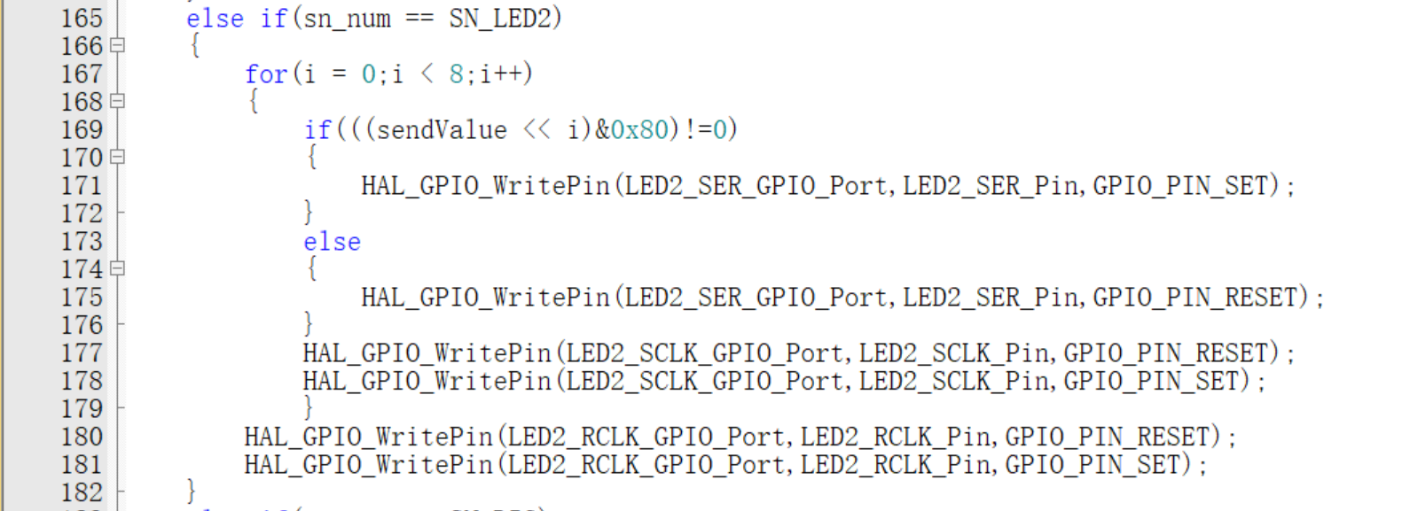
If SN_SUM = SN_LED2, the microcontroller first controls the relevant pins of the second 74HC595 chip, sending the data to be lit to the second 74HC595. The 74HC595 then transmits the data to the first seven-segment display. If the data is the first segment code, the display code for the second segment code is sent. This process continues, lighting up the seven-segment displays one by one.
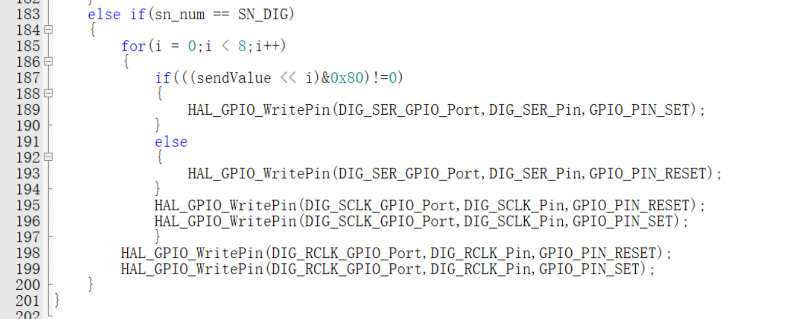
If SN_SUM = SN_DIG, the microcontroller first controls the relevant pins of the third 74HC595 chip. The third seven-segment display primarily lights up the segment codes. If the data is the first segment code, the display code for the first segment code is sent. This process continues, lighting up the seven-segment displays one by one.
Sensor numerical communication I2C code
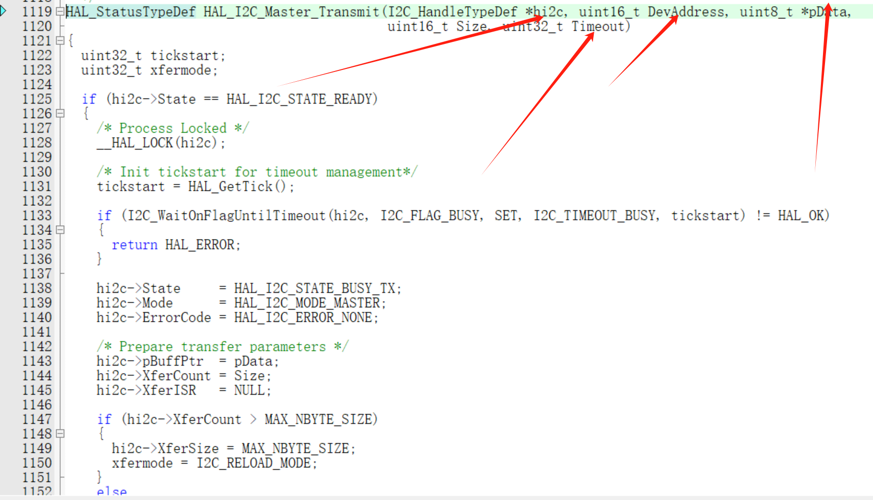
host send function call parameter description (receive function is basically the same);
*hi2c represents the IIC handle; DevAddress represents the device address, 8 bits of data, which will be automatically padded at the end during transmission; *pData represents the data to be sent; Size is the length of the data to be sent; Timeout is the response timeout;
The following code indicates that a measurement command is sent and the relevant data is read to calculate the temperature and humidity values; According to the chip manual, Sensirion's calculation formula for the temperature and humidity sensor measurement values can be seen:
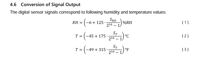
So temperature value = (temperature data sent by the sensor * 175) / 65535 - 45;
humidity value = (humidity data sent by the sensor * 125) / 65535 - 6;

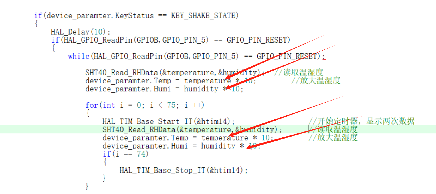
The following code means that since the microcontroller is not good at displaying decimal temperature and humidity values through the digital tube, the temperature and humidity values are multiplied by 10 to become a 3-digit integer, and the values are extracted by taking the millions, tens, and units digits respectively, and then displayed on the digital tube.
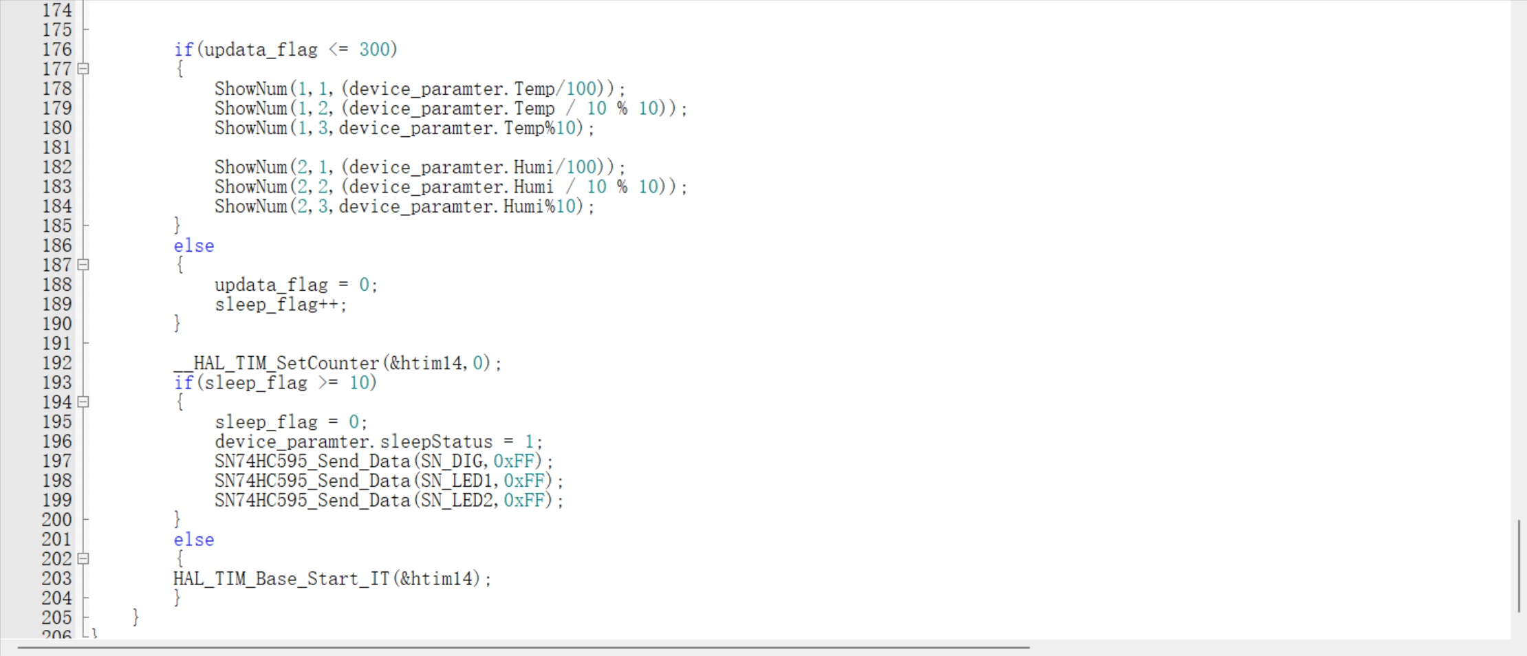
This section indicates that the read values will be displayed on a digital tube. Due to low-power settings, the display cannot remain constantly lit within a while loop; instead, it is displayed within an interrupt, with the temperature and humidity values displayed on the digital tube at half-minute intervals.

Threshold judgment and buzzer alarm codes
are included in certain situations, such as venues for cultural relics, antiques, and art collections. These places are highly sensitive to temperature and humidity. Excessively high or low temperatures and humidity can have significant impacts on artworks or antique collections. For example, excessively high temperatures may cause cracking in some Phoebe zhennan wood, while excessively high humidity may cause valuable wooden furniture or paintings to become damp and moldy, resulting in considerable damage. Therefore, I have added temperature and humidity threshold judgment and alarm functions to the original low-power temperature and humidity display to respond promptly to temperature and humidity information and make timely adjustments and responses, reducing damage and impact on artworks and collections.
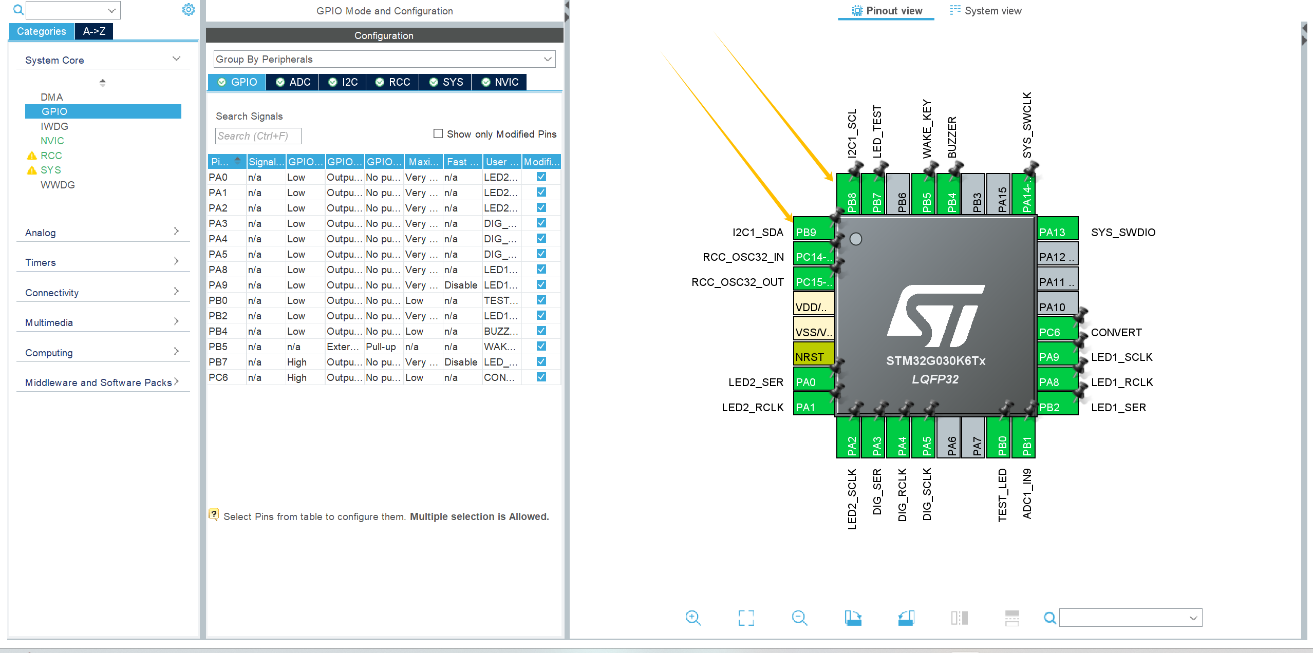
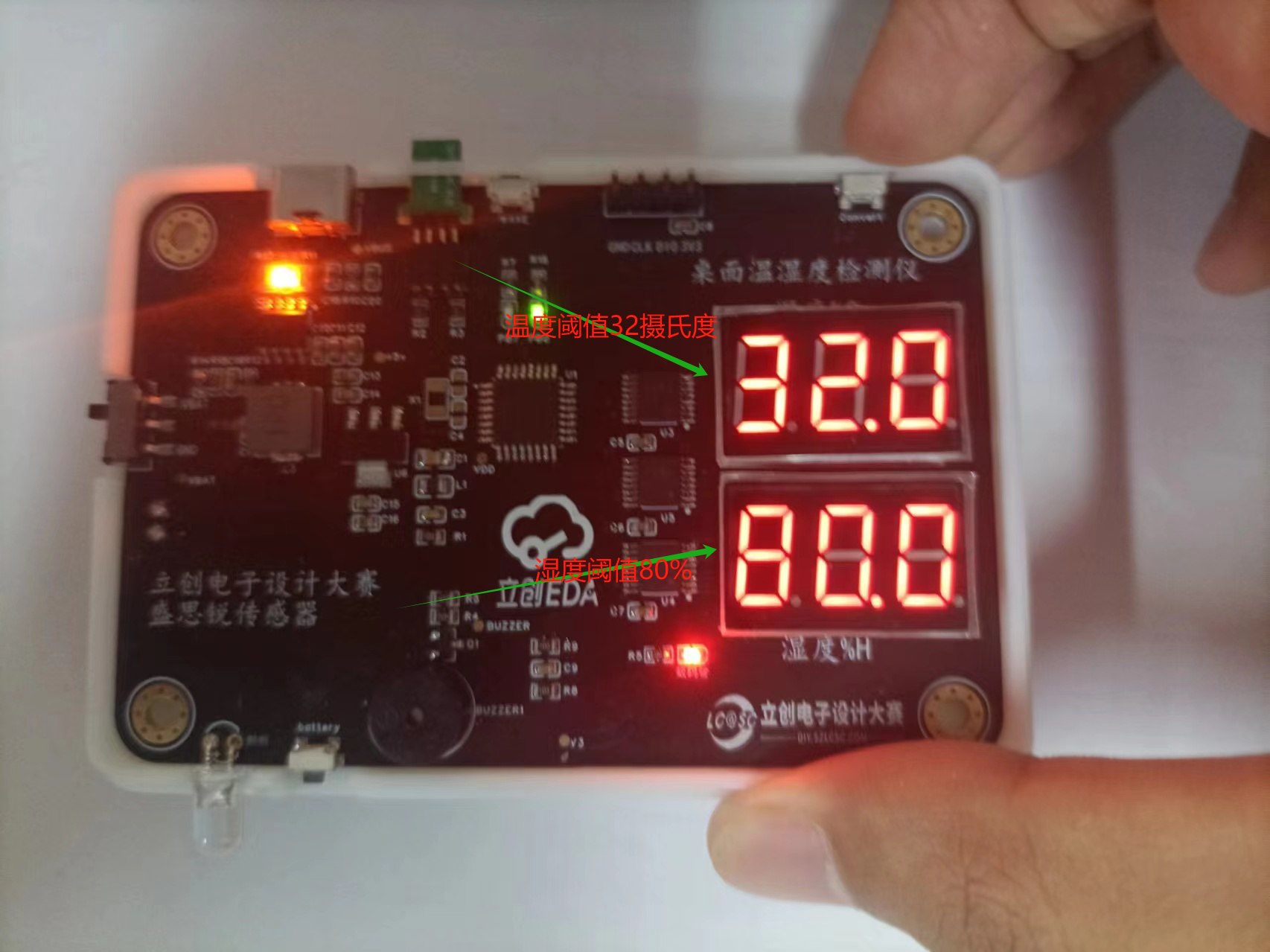
Therefore, I added a buzzer response circuit. According to relevant literature, the optimal temperature for artworks and collectibles is 25-32 degrees Celsius, with a maximum temperature not exceeding 32 degrees Celsius and humidity below 80%; exceeding 80% may cause artworks and collectibles to become damp and moldy. Therefore, I added threshold judgment code to the code; when the temperature exceeds 32 degrees Celsius or the humidity exceeds 80%, a temperature and humidity alarm function is triggered. First, configure and initialize the GPIO ports on the CubeMX:

The following is the threshold judgment code:
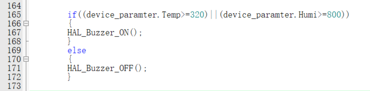
The image below shows the threshold value displayed when I press the Convert button.
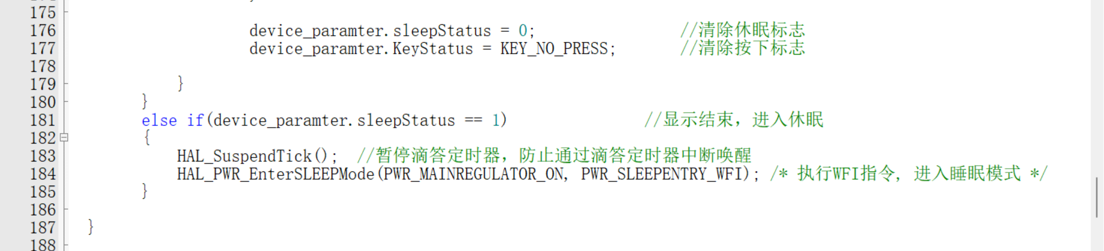
Software low-power design:
Consulting the chip manual reveals that the selected chip is the STM32G030K6T6. The STM32G030K6T6's sleep mode refers to its entry into a low-power state to minimize power consumption without affecting the processor's basic functions. Common sleep modes in the STM32G030K6T6 include:
Sleep mode: also known as sleep mode, is a low-power mode that can be triggered by software. In this mode, the CPU and memory stop running, but the clock and peripherals continue to operate. The processor enters a low-power state to minimize power consumption, but can be quickly woken up to respond to external interrupts or events.
Stop Mode: Stop mode is a deeper low-power mode that further reduces system power consumption. In Stop mode, the CPU, memory, peripheral clocks, and main clock can all be stopped or slowed down. A wake-up source is required to wake up the system, such as an external interrupt, RTC alarm, or timer interrupt.
Standby Mode: Standby mode is one of the lowest power modes, further disabling the main clock. In this mode, only the RTC and some critical peripherals are kept running at low power. Wake-up typically requires a longer startup time.
To set the STM32G030K6T6 into low-power mode, the following steps are usually required: First, initialize and configure, ensuring all unnecessary peripherals and clocks are turned off or adjusted to their lowest power state. For example, turn off unused peripheral clocks and stop their operation. Second, select the appropriate low-power mode, choosing the appropriate sleep mode (Sleep, Stop, or Standby) based on application requirements. Then, configure the wake-up source according to the wake-up conditions. This can be achieved by configuring relevant registers, such as external interrupt lines, RTC alarms, and timers. To enter low-power mode, execute the corresponding instructions or functions to put the processor into the selected low-power mode. For example, when using the HAL library, you can call HAL_PWR_EnterSleepMode() or a similar function. To exit low-power mode, the processor will automatically resume from low-power mode when the wake-up condition is met, and continue execution in the interrupt service routine or the main program.
Problems encountered and solutions
1. The digital tube cannot be lit up
after troubleshooting step by step. It was found that I used a common anode digital tube, while the official digital tube is a common cathode type. So I learned the working principle of common anode and common cathode digital tube and modified the code. First of all, the code array for lighting up the common anode digital
tube should be: static uint16_t sgh_value[11]={0xC0,0xF9,0xA4,0xB0,0x99,0x92,0x82,0xF8,0x80,0x90,0x7F};
First of all, the code array for lighting up the common cathode digital tube should be: static uint16_t sgh_value[11]={0xbf,0x86,0xdb,0xcf,0xe6,0xed,0xfd,0x87,0xff,0xef,0xf7,0xfc};
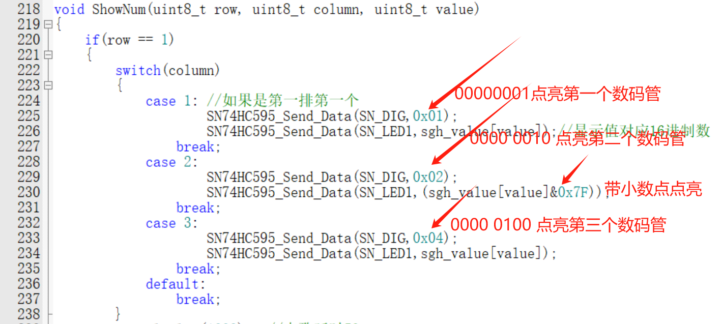
Therefore, the digital tube lighting array in the project is modified as follows:

The segment code is lit by high-level lighting, so the code needs to be modified as follows; The decimal point code is 0X70, then sgh_value[value]&0x7F represents the displayed value and simultaneously displays the decimal point
blanking should be modified. Revised as follows:

Reflections and Thoughts
: This is my second time participating in the training camp. Although I didn't win any prizes in the previous camps, I've truly learned a lot each time. From a complete beginner who initially disliked the knowledge in analog and digital electronics textbooks, to now being able to design and run circuits myself, I've benefited immensely from this journey. It allows me to learn through play and play through learning, gradually deepening my enjoyment of hardware learning. I'm truly grateful to JLCPCB for providing such a great platform, allowing us to learn through playing with hardware. I sincerely wish JLCPCB continued success, constant innovation, and new breakthroughs.
*6. BOM List

* 7. Competition Logo Verification
* 8. Demo your project and record a video to upload to
Bilibili. Demo link (Ctrl + tap the blue text to jump): JLCPCB & STM32-based Low-Power Desktop Temperature and Humidity Detection and Threshold Alarm Device
Bilibili Demo Link: https://www.bilibili.com/video/BV1DEiceTEVB/?spm_id_from=333.337.search-card.all.click&vd_source=1a0773535eda8ace0b6069f8be099662
Go to view more details >


 京公网安备 11010802033920号

 SAFC903A70STC02


