Download links for CH592 datasheet, example packages, etc.
Program download tool link:
Press and hold the boot button while inserting the board into the computer to download the program.
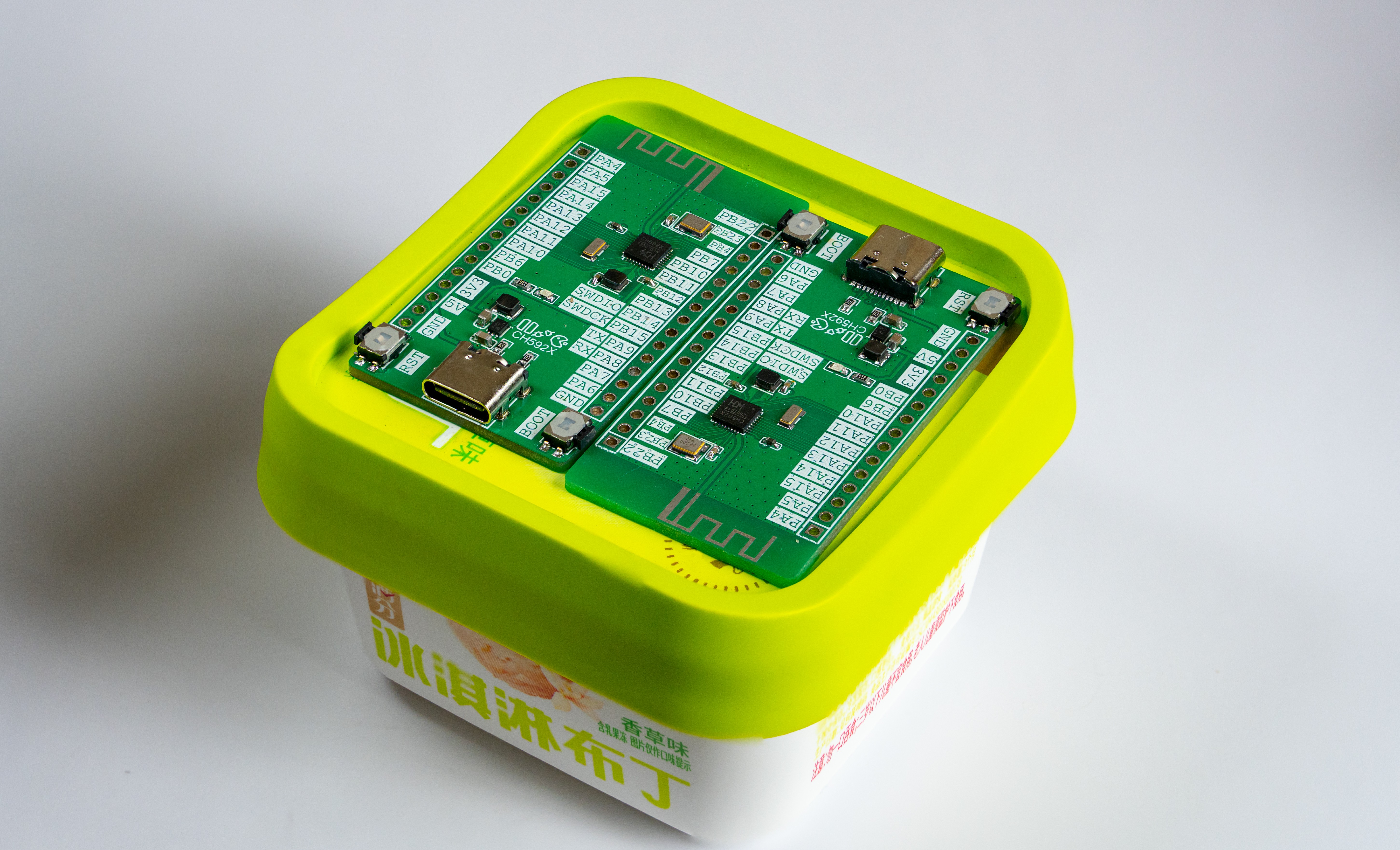
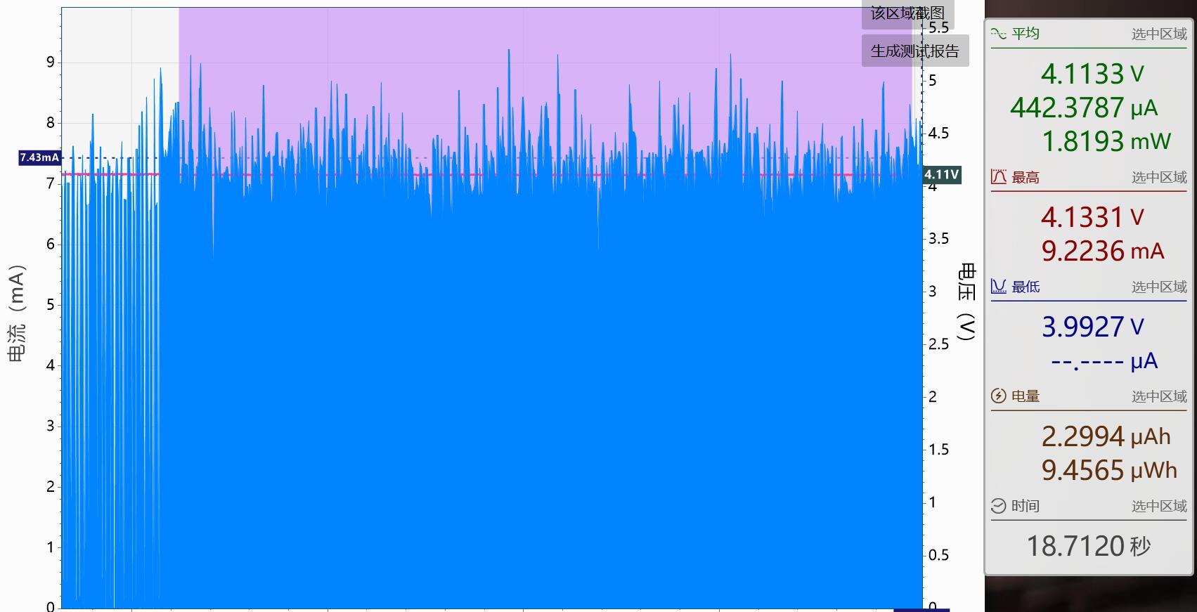
Power consumption test of the BLE keyboard example: Signal strength 0dBm, DC-DC enabled, sleep mode enabled.
CH592X Development Board Test.zip
CH592X Development Board Test.hex
PDF_CH592X Minimal System Development Board.zip
Altium_CH592X Minimal System Development Board.zip
PADS_CH592X Minimal System Development Board.zip
BOM_CH592X Minimal System Development Board.xlsx
93407
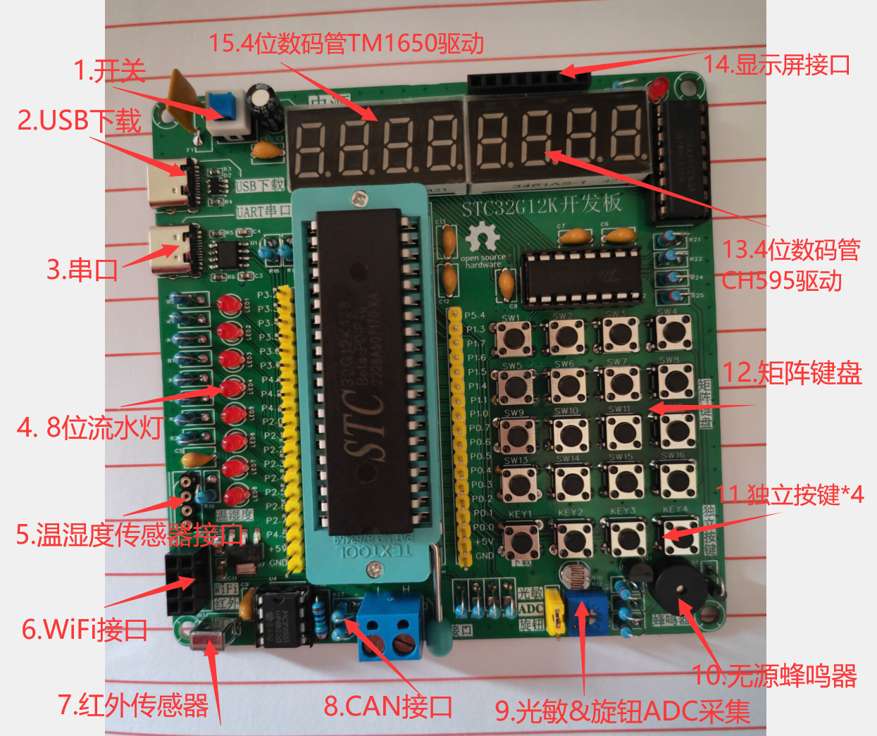
STC32G12K128 Development Board
Classic straight-in connector! Wide range of peripherals! Beginner-friendly!
I. Project Overview
This project uses the STC32G12K128 Beta-IDIP40 chip as the main controller. Compared to the classic 89C51/89C52, this chip offers more code space and richer on-chip peripheral resources. The board size is 10x10cm, and it extensively uses through-hole component packages, paying homage to the classics with a strong postmodern cyberpunk archaeology feel. With abundant onboard peripherals and every pin on the chip utilized, it is particularly suitable for beginners to learn about 51 core hardware and practice soldering techniques. The average cost per board is under 35 RMB (price referenced from the July 2024 market, calculated by averaging the total cost of 5 development boards and then adding a 150% premium), making it an excellent choice for beginners and training.
II. Resource Introduction
Main Control Chip: STC32G12K128 Beta-IDIP40
Power Supply Overview: Except for the WiFi interface which uses 3.3V power, all other devices use 5V power from USB output. Download
and Debugging: One USB-to-serial port (P3.6/P3.7) for debugging, one USB download interface
. Onboard Peripherals:
8-digit LED
passive buzzer,
universal screen interface (compatible with IIC bus and SPI bus screens)
, CAN communication interface,
infrared receiver,
1-channel ADC acquisition (optional light intensity or potentiometer),
temperature and humidity acquisition (compatible with DS18B20 and DHT11),
4-digit LED display (74HC595 driver)
, 4-digit LED display & 4*4 matrix keypad (TM1650 driver).
4 independent buttons (KEY1 can be used for downloading simultaneously)
WiFi communication interface (ESP01S)
III. Usage Instructions: Ready to use
immediately after opening the package. Do not insert into 51 microcontrollers, as the pins are incompatible. Please refer to the datasheet.
IV. Attachments:
I've been a bit busy lately, so I just wrote a simple LED display. See the video later for the effect. The Keil project is at the end. Updates to other onboard peripheral examples will be after December 24th, 2024. See you later!
STC32_SMG.zip
Flowing Lights.mp4
PDF_STC32G12K128 development board.zip
Altium_STC32G12K128 development board.zip
PADS_STC32G12K128 development board.zip
BOM_STC32G12K128 development board.xlsx
93408
FunKey-A32G Open Source Handheld Game (Allwinner V3S) 2-Layer Full Board Version
FunKey-A32G Open Source Handheld Game (Allwinner V3S) 2-Layer Full Board Version
This version is a 2-layer full board solution for FunKey A32G. Prototype fabrication is a paid service.
The parts list and fabrication tutorial can be found at FunKey A32G-4-layer board. For
4-layer board solutions, please also visit FunKey A32G-4-layer board.
Alternatively, join our discussion groups:
FunKey Enthusiast Group 1: 825088536 (full)
and FunKey Enthusiast Group 2: 921179758 (may require a password; just enter anything).
PDF_FunKey-A32G Open Source Handheld Game (Allwinner V3S) 2-layer Full Board Version.zip
Altium_FunKey-A32G Open Source Handheld Gamepad (Allwinner V3S) 2-layer Full Board Version.zip
PADS_FunKey-A32G Open Source Handheld Gamepad (Allwinner V3S) 2-Layer Full Board Version.zip
BOM_FunKey-A32G Open Source Handheld Game (Allwinner V3S) 2-Layer Full Board Version.xlsx
93410
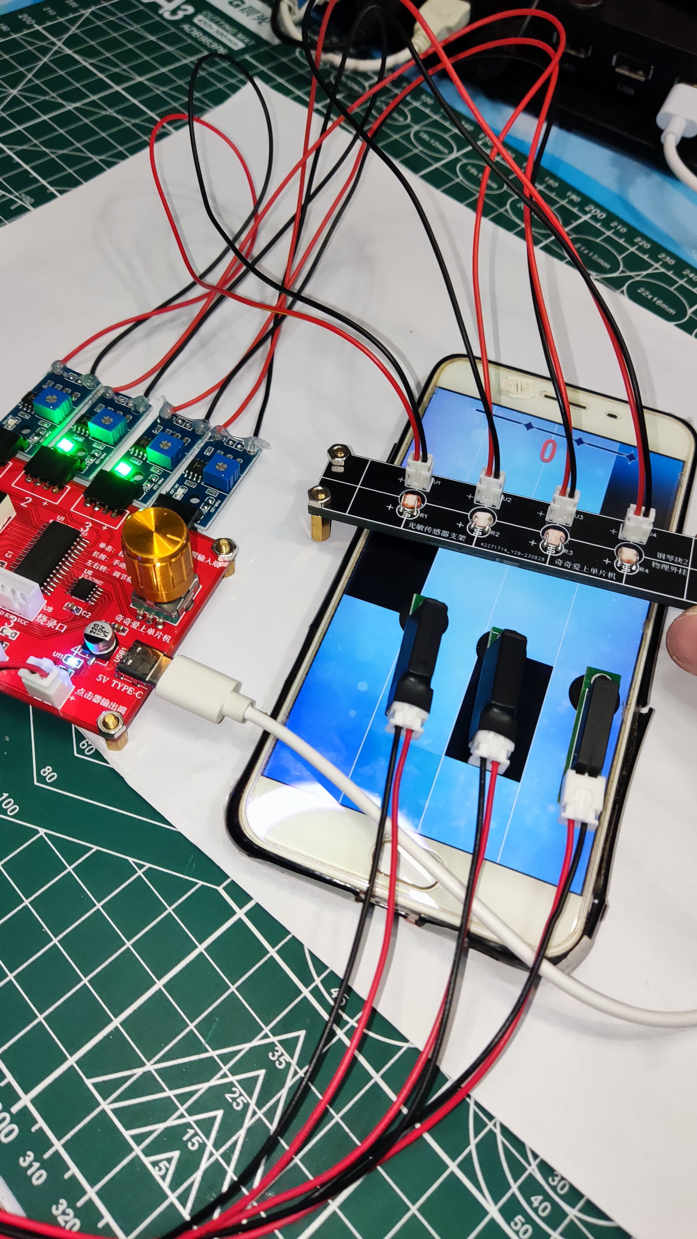
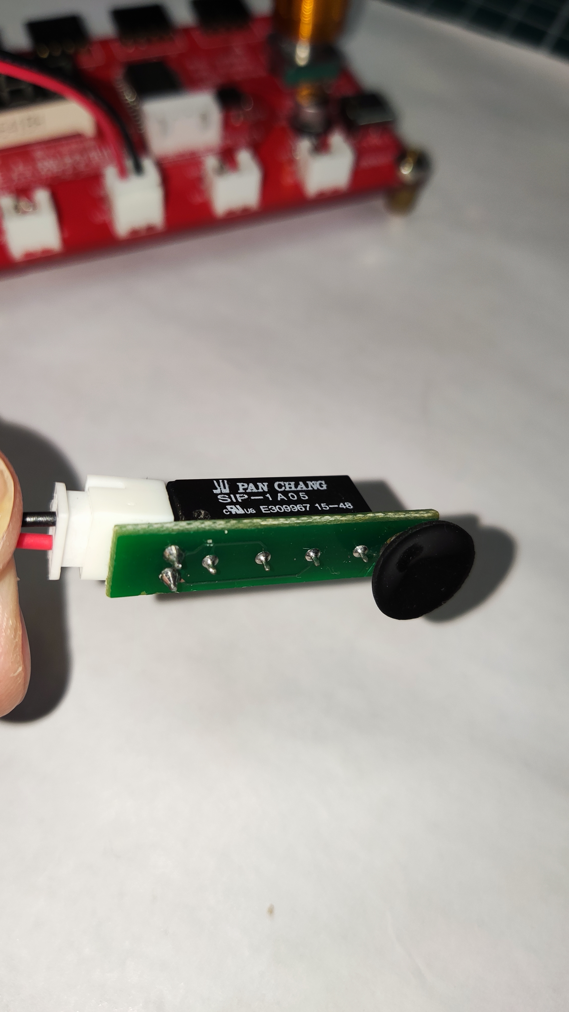
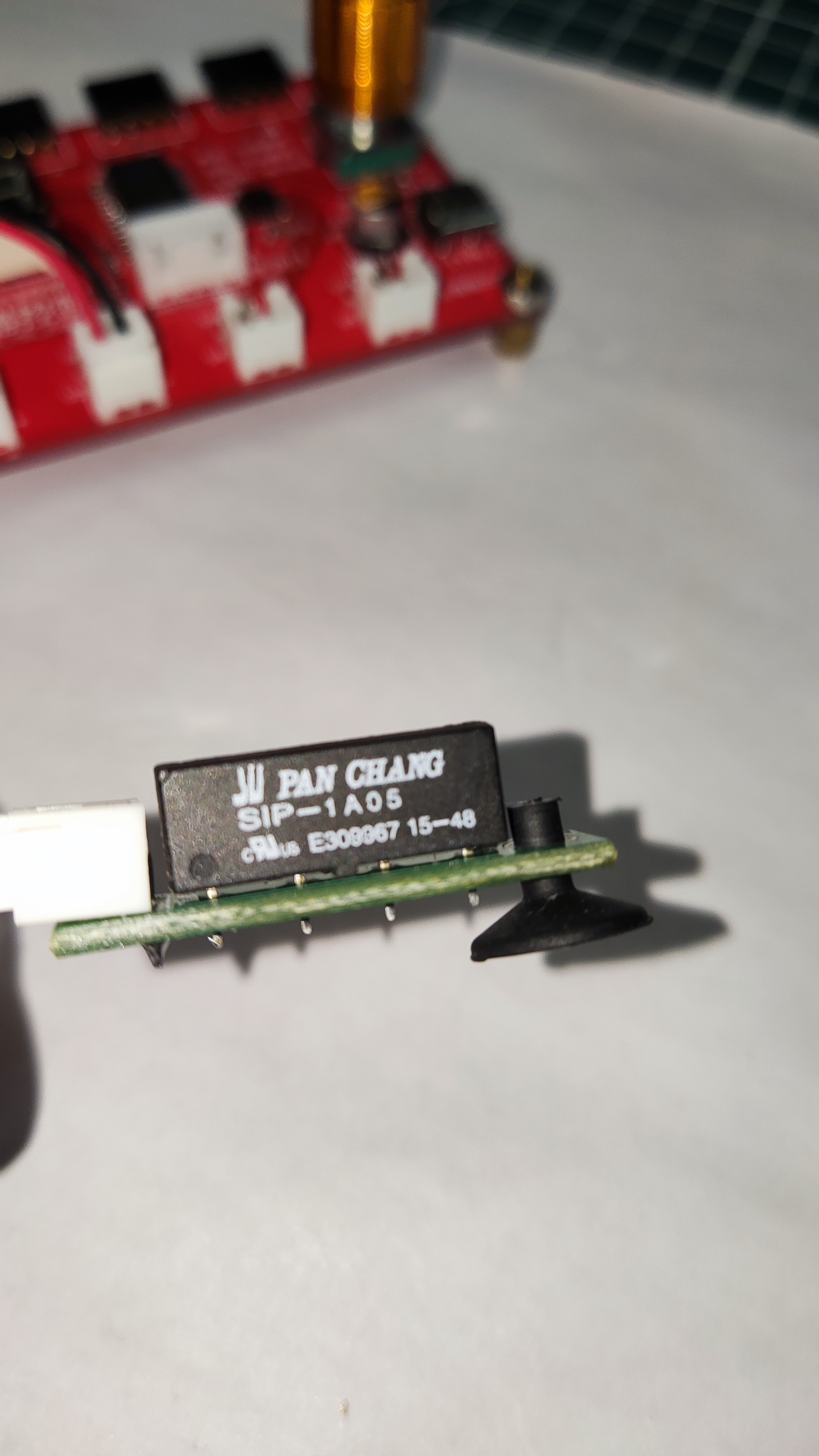
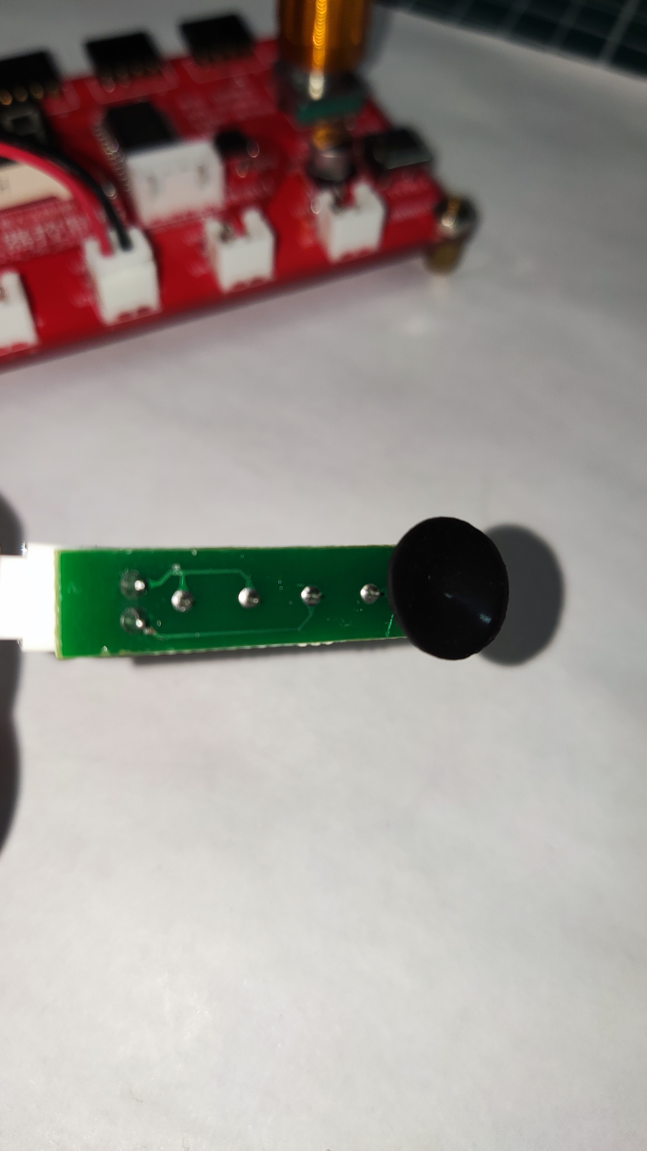
Mobile phone screen auto-clicker
The simplest mobile clicker combined with a control panel enables a game of liking and playing piano tiles.
The simplest mobile phone clicker, combined with a control board, enables a "like" and "piano tile" game.
You can buy a PUBG-like suction cup (available on Taobao) to play; the principle of GND conduction and high-level disconnection achieves double-tap likes.
A video demonstration can be viewed on my Douyin account. The accompanying clicker control board is also open-source in my projects.

//The source code and PCB for the above projects are publicly available. Search for the username "Qiqi Loves Microcontrollers" on the "LCSC Open Source Hardware Platform".
/*No technical support provided, just sharing for free out of passion. An open-source blogger; projects are for use only, not for commercial purposes. Questions can be discussed in the comments section below. Designer: Qiqi
Douyin: The Cutest Qiqi in the Universe Kuaishou ID: Qiqi Loves Microcontrollers Bilibili: Qiqi Loves Microcontrollers QQ: 1715755109 (For custom microcontroller programs and PCB designs, add as a friend and indicate your purpose; paid design, serious inquiries only). QQ Group: 499067314 (Welcome all microcontroller enthusiasts to join the group; group files and materials are available for free download). */ /
Clicker video demonstration.mp4
PDF_Mobile Screen Taper Clicker.zip
Altium_Mobile Screen Taper Clicker.zip
PADS_Mobile Screen Taper Clicker.zip
BOM_Mobile Screen Clicker/Clicker.xlsx
93411
Location and Communication Services Module
Location and 4G communication service module compatible with ZTE E610
This replica of the location and 4G communication service module common to the ZTE E610 eliminates the need for soldering the impedance matching circuit and CH32 microcontroller circuit during replication; the 485 jumper can be directly connected. This results in a smaller size and easier portability.
PDF_Location and Communication Services Module.zip
Altium Location and Communication Services Module.zip
PADS Location and Communication Services Module.zip
BOM_Location and Communication Services Module.xlsx
93413
Low-power PWM output
Temperature control PWM, used in chassis or indoor applications
In the sweltering summer heat, when camping outdoors, a cool breeze is essential. This project, based on a 51 microcontroller, controls two channels of PWM wave output and allows for adjustable wind speed via Bluetooth control. Bluetooth commands are sent as: auto (automatic mode) and game (full-speed mode). The video shows it installed in the host computer case.
176ee3a41313535b6a754f9a17559e58.mp4
eb5c4b2315b09324fadc6152c0471867.mp4
PWM low-power output code.zip
PDF_Micropower PWM Output.zip
Altium_MicropowerPWMOutput.zip
PADS_Micropower PWM Output.zip
BOM_Micropower PWM Output.xlsx
93414
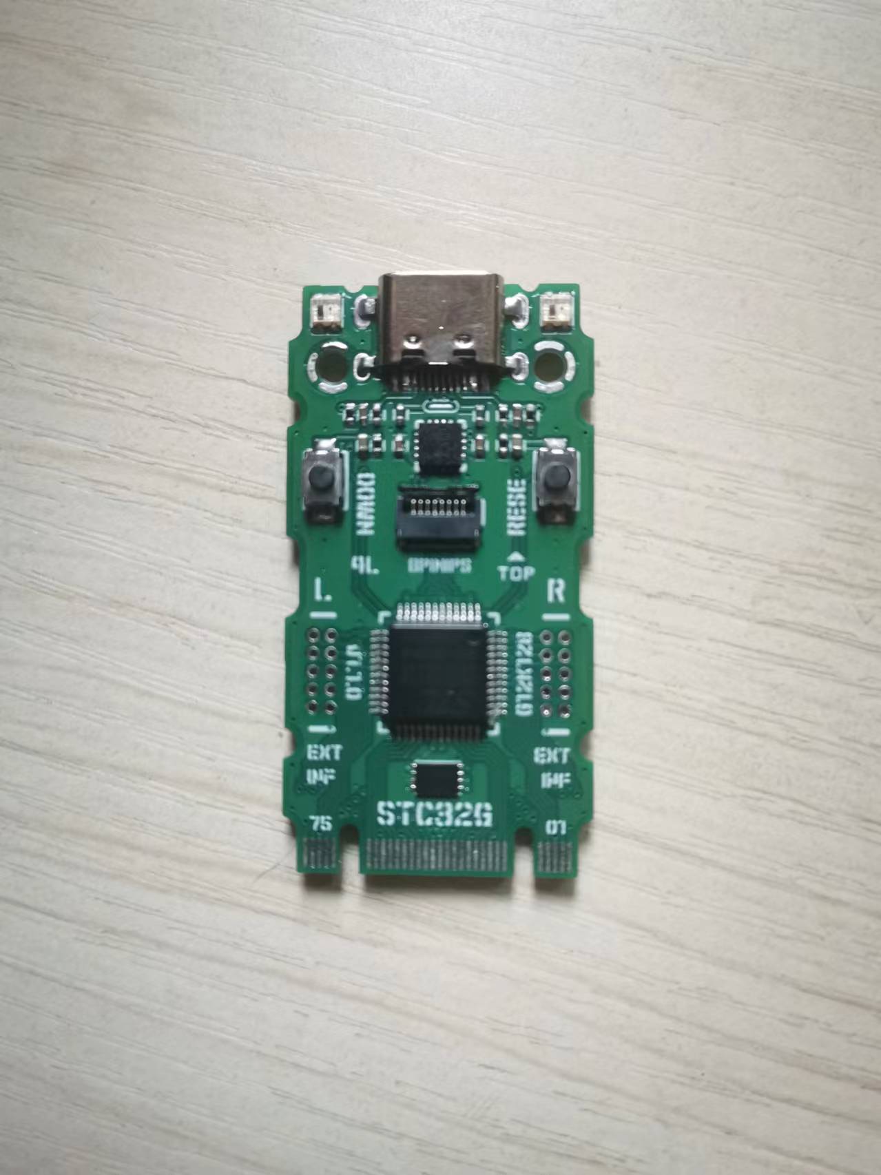
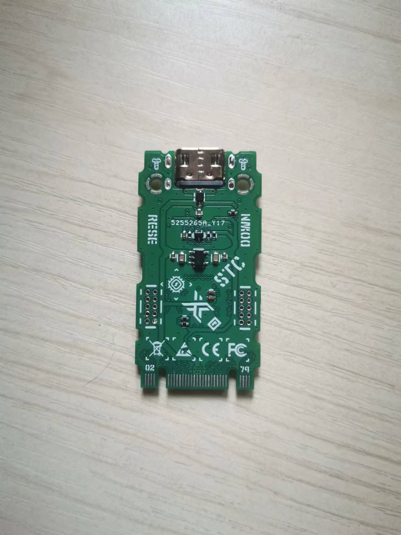
M2CB-STC32G
An STC32G12 core development board with an M.2 interface.
This core
version is based on the STC32G design and is inspired by the official Dragon Slayer development board.
Based on: STC32G12K128, 32-bit 8051 core (1T), approximately 70 times faster than traditional 8051.
Supports: UART, USART, ADC, advanced PWM, SPI, I2C, I2S, USB, CAN, LIN, RTC, DMA, etc.
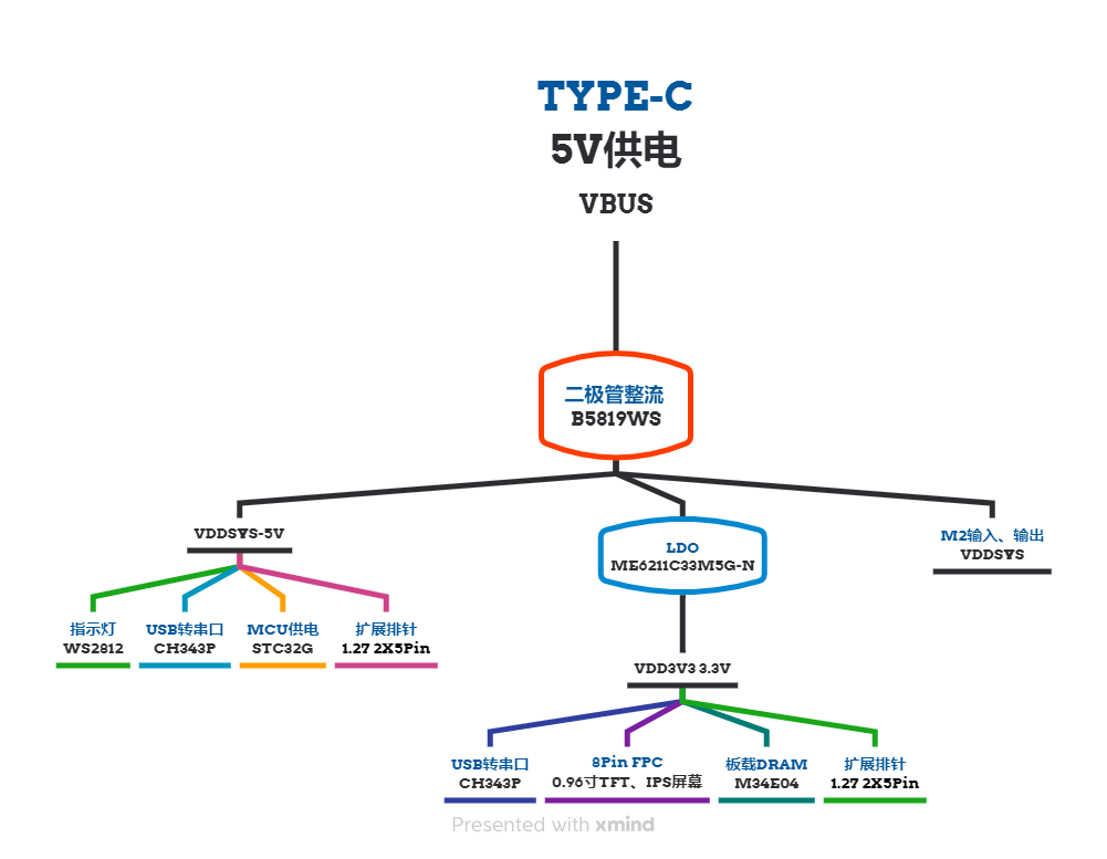
IC: Onboard STC32GMCU, CH343P, M34E04
Interfaces: Onboard TYPEC, expansion header, 8-pin TFT, IPS screen interface, DIY M&M-Key M.2 interface
Supported programming platforms: ARM, Keil, etc.
All I/O ports have
two WS2812 LEDs. Reserved
8-pin TFT, IPS, SPI screen interfaces (note I/O conflicts).
Update Log
July 26, 2024 V1.1.0 Project Progress
Project Initiation
Feasibility Assessment
Solution Verification
Layout
Material Selection
Board Verification
Software Development
Project Completion
Specifications
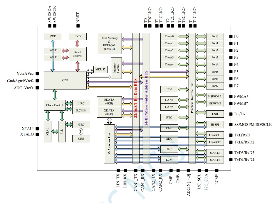
Specifications MCU STC32G12K128-35I-LQFP48 High-speed 32-bit 8051 core (1T) Operating voltage: 2V~5.5V (Type-C, 1.27 expansion header, M.2 interface power supply) Operating temperature: -20℃~65℃ Flash memory: 128K bytes FLASH program memory (ROM) SRAM: 4K bytes internal SRAM (edata), 8K bytes internal extended RAM (internal xdata) Clock source : Internally integrated 4 clock sources Interrupts: INT0-4, Timer 0-4, USART1~4, ADC, DAC, LVD low voltage detection, SPI, I2C, comparator, PWMA, PWMB, USB, CAN, CAN2, LIN, LCMIF color screen interface interrupt, RTC real-time clock, all I/O interrupts (8 groups), DMA receive and transmit interrupts for serial port 1, serial port 2, serial port 3, serial port 4, I2C DMA receive and transmit interrupts, SPI The system supports DMA interrupts for the ADC, LCD driver, and memory-to-memory DMA. All GPIOs support quasi-bidirectional ports, push-pull output, open-drain, and high-impedance input modes. System block diagram: Please fill in the project design summary (within 300 characters). Functional block diagram, power supply diagram , overall design scheme block diagram , physical display. Important notes: Due to time constraints, the software is not yet fully verified; proceed with caution when designing the board!!!

PDF_M2CB-STC32G.zip
Altium_M2CB-STC32G.zip
PADS_M2CB-STC32G.zip
BOM_M2CB-STC32G.xlsx
93415
electronic


 京公网安备 11010802033920号

 SA324160F56HLR


