1. Schematic Design
(1) The main control circuit design
uses STC32G12K128 as the main control chip. The working voltage is 1.9V~5.5V. It has a high-speed 32-bit 8051 core, which is more than 70 times faster than the traditional 8051. It also has 49 interrupt sources, 4 interrupt priority levels, 5 16-bit timers, 4 high-speed serial ports, 2 sets of advanced PWM functions, etc. It also supports direct USB programming without the need for a programmer, which can provide great convenience.
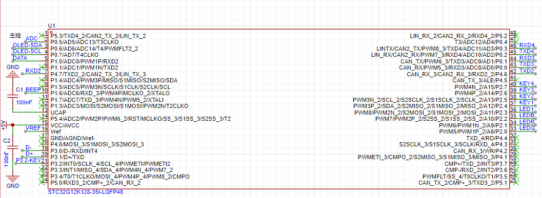
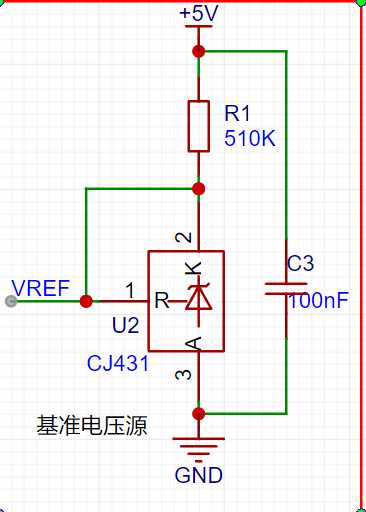
According to the chip's datasheet, a filter capacitor needs to be added at VCC. A capacitor also needs to be connected to the UCAP pin. The Vref pin must not be left floating. It is the pin of the external reference power supply of the ADC. It must be connected to either VCC or an external reference power supply. In this project, it is connected to an external reference power supply, as shown in the figure below. A 2.5V reference power supply is provided by CJ431.
(2) Power supply circuit design:
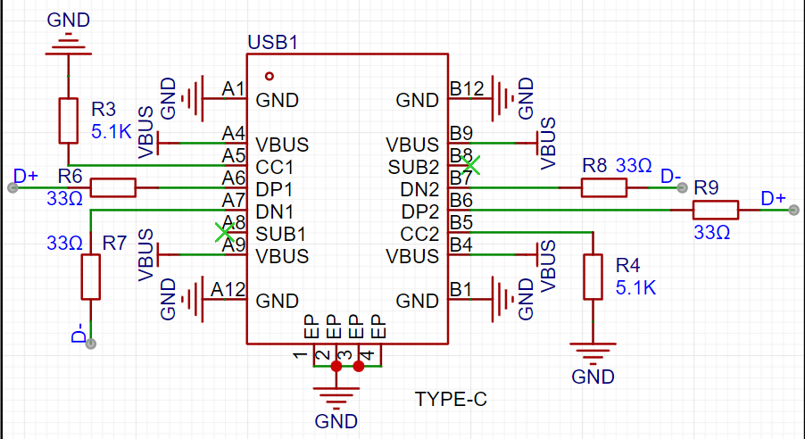
In this project, TYPE-C is used for voltage power supply and USB download can be performed directly as shown in the figure below. Note that a TYPE-C with data transmission capability must be used, otherwise the download will not be possible. CC1 and CC2 cannot be left floating.
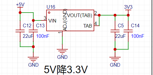
(3) Step-down circuit design:
In this project, a 3.3V power supply is required, so we need a step-down circuit as shown in the figure below. An LDO is used for step-down. Capacitors are required at the input and output, as stated in the datasheet.
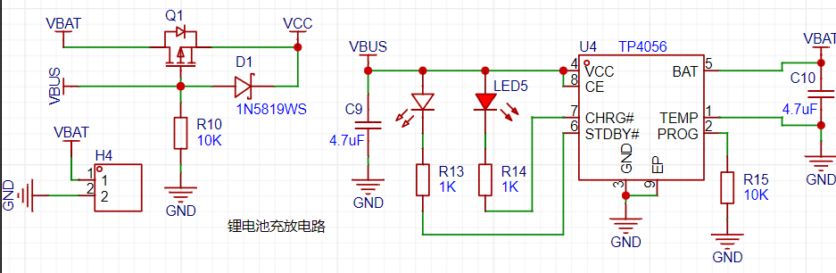
(4) Power switching circuit and lithium battery charging circuit design:
In this project, TYPE-C or lithium battery can be used for power supply. The figure below shows a classic power switching circuit. When TYPE-C is used for power supply, the MOSFET will be cut off, and TYPE-C will supply power and charge the battery. When no external power supply is connected, the MOSFET will be turned on and the battery will supply power.
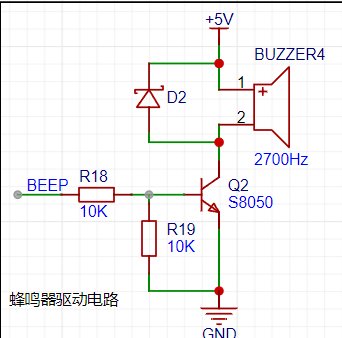
(5) Buzzer drive circuit:
In this project, a buzzer is used as the sound source for the alarm clock. A passive buzzer is used, and a transistor is used to amplify the current to drive the buzzer.
(6) The WIFI module design
uses the ESP8266 module to connect to the serial port 2 of the STC32 microcontroller to obtain network time and weather.

(7) The temperature and humidity sensor circuit design
uses the DHT11 temperature and humidity sensor to read temperature and humidity. Because it uses single bus timing, the data line needs to be pulled high when idle, so a pull-up resistor is used in the circuit.

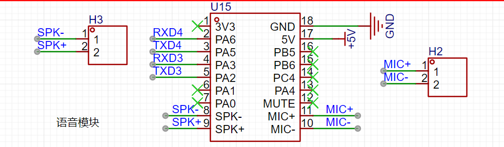
(8) The voice recognition module circuit design
uses the Tianwen ASR-PRO module to recognize and broadcast voice.
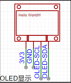
(9) The OLED circuit design
uses an OLED screen to display the interface.
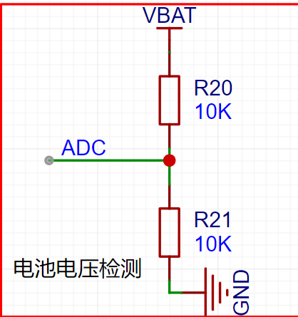
(10) The battery voltage detection circuit design
uses the ADC reference voltage of 2.5V in this project. The external power supply and battery power supply are both greater than 2.5V, so two 10K resistors are used to divide the voltage to half of the original voltage. Then, the measured data is doubled in the code to obtain the measured voltage.
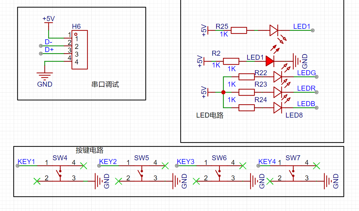
The following circuits are the debugging circuit, button circuit, and LED circuit. RGB lights are used to display multiple colors, which will look better.
Part Two: Software Design.
The software design section will discuss how to obtain network time and weather using the ESP8266, a part that took a considerable amount of time. Here, the ESP8266 is used to connect to the network to read the network time and weather. The ESP8266's AT command set is used to connect to a TCP server to read the network time. Commands are sent to the ESP8266 via the STC32's serial port 2 to obtain the time. Because it seems the Suning API is no longer working, I searched online for a long time before finding a working one: http://api.k780.com:88/?app=life.time&appkey=10003&sign=b59bc3ef6191eb9f747dd4e83c99f2a4&format=json&HTTP/1.1. Using the following commands, you can connect to the API and obtain data returned by the ESP8266. Next, we need to extract the valid data from this data using string functions. The following data is returned by the URL:
`AT+RSTAT+CWMODE=1AT+CIPMUX=0AT+CWJAP="iphone xxxx","wjm590509"AT+CIPSTART="TCP","api.k780.com",80AT+CIPMODE=1AT+CIPSENDGET http://api.k780.com:88/?app=life.time&appkey=10003&sign=b59bc3ef6191eb9f747dd4e83c99f2a4&format=json&HTTP/ 1.1`: `{"success":"1","result":{"timestamp":"1719986635","datetime_1":"2024-07-03` 14:03:55","datetime_2":"2024骞?7鏈?3鏃?14鏃?3鍒?5绉?,"week_1":"3","week_2":"鏄熸湡涓?,"week_3":"鍛ㄤ笁","week_4":"Wednesday"}} We need to use the strstr function to locate the datetime_1 string and then extract the data after it. However, the extracted data is not decimal but a string. We need to use the atio function to convert the string to decimal. Getting the weather is a similar operation. We can use the weather app to get weather information. There are paid and free versions. The free version only has temperature and weather conditions, while the paid version has more. The free version seems to be usable as well. The following is the AT command to retrieve the weather: AT AT+RSTAT+CWMODE=1 AT+CIPMUX=0 AT+CWJAP="iphone xxxx","wjm590509" AT+CIPSTART="TCP","api.seniverse.com",80 AT+CIPMODE=1 AT+CIPSENDGET https://api.seniverse.com/v3/weather/now.json?key=SaH8Ifm9HSdWY5stg&location=shenzhen&language=en&unit=c Returned data: {"results":[{"location":{"id":"WS10730EM8EV","name":"Shenzhen","country":"CN","path":"Shenzhen,Shenzhen,Guangdong,China","timezone":"Asia/Shanghai","timezone_offs et":"+08:00"},"now":{"text":"Sunny","code":"0","temperature":"32"},"last_update":"2024-07-07T17:04:39+08:00"}]}
The code is the weather code; you can refer to the description table to display the weather. (Description table URL: https://seniverse.yuque.com/hyper_data/api_v3/yev2c3?)
(PS: You need to exit the pass-through mode at the end, because reading data requires entering the pass-through mode. If you don't exit, subsequent transmissions will produce garbled characters. Sending +++ without a newline will exit the mode.)
I found that the STC32 header file does not have the strstr function, so we need to rewrite this function. As shown below:
`char * strstr ( const char * str1, const char * str2 ){char *cp = (char *) str1;char *s1, *s2;
if ( !*str2 )return((char *)str1);
while (*cp){ s1 = cp;s2 = (char *) str2;
while ( *s1 && *s2 && !(*s1-*s2) )/*In C language, subtracting pointers gives the number of elements*/s1++, s2++;
if (!*s2)return(cp);
cp++; }
return(NULL);
}`
The rest of the code is in the attachment, but some parts are not yet complete. I haven't had time to write the speech recognition and broadcast functions because I'm busy. I'll add them later when I have more free time.
The video demonstrates setting the network time and alarm clock, as well as temperature and humidity detection.
Finally, thank you to JLCPCB and STC for supporting this event! Wishing JLCPCB and STC all the best!


 京公网安备 11010802033920号

 1206J1000470PCTE01


