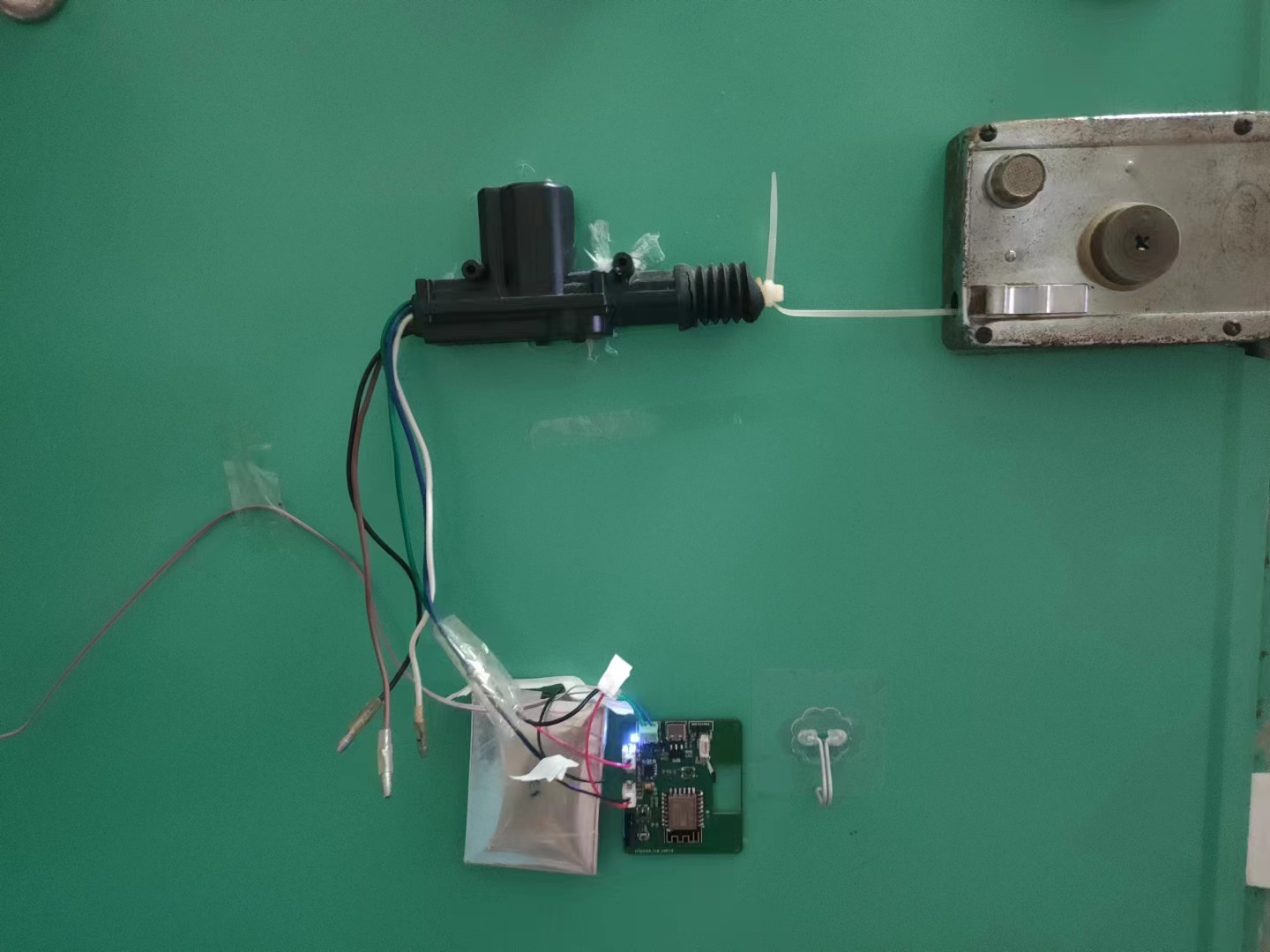
This project is a remote door opening module for old-fashioned anti-theft locks in rental apartments. It uses a simple and straightforward door opening solution, solving my frequent hassle of forgetting my keys and having to ask the landlord for them. It's primarily based on Blinker's IoT solution
(mainly free). Blinker features include: Blinker documentation center.
The module uses a simple door opening solution made from a cheap second-hand lever motor and a cable tie (available on Taobao for a few dollars). (The module also has an SG90 servo motor interface; you can design your own).
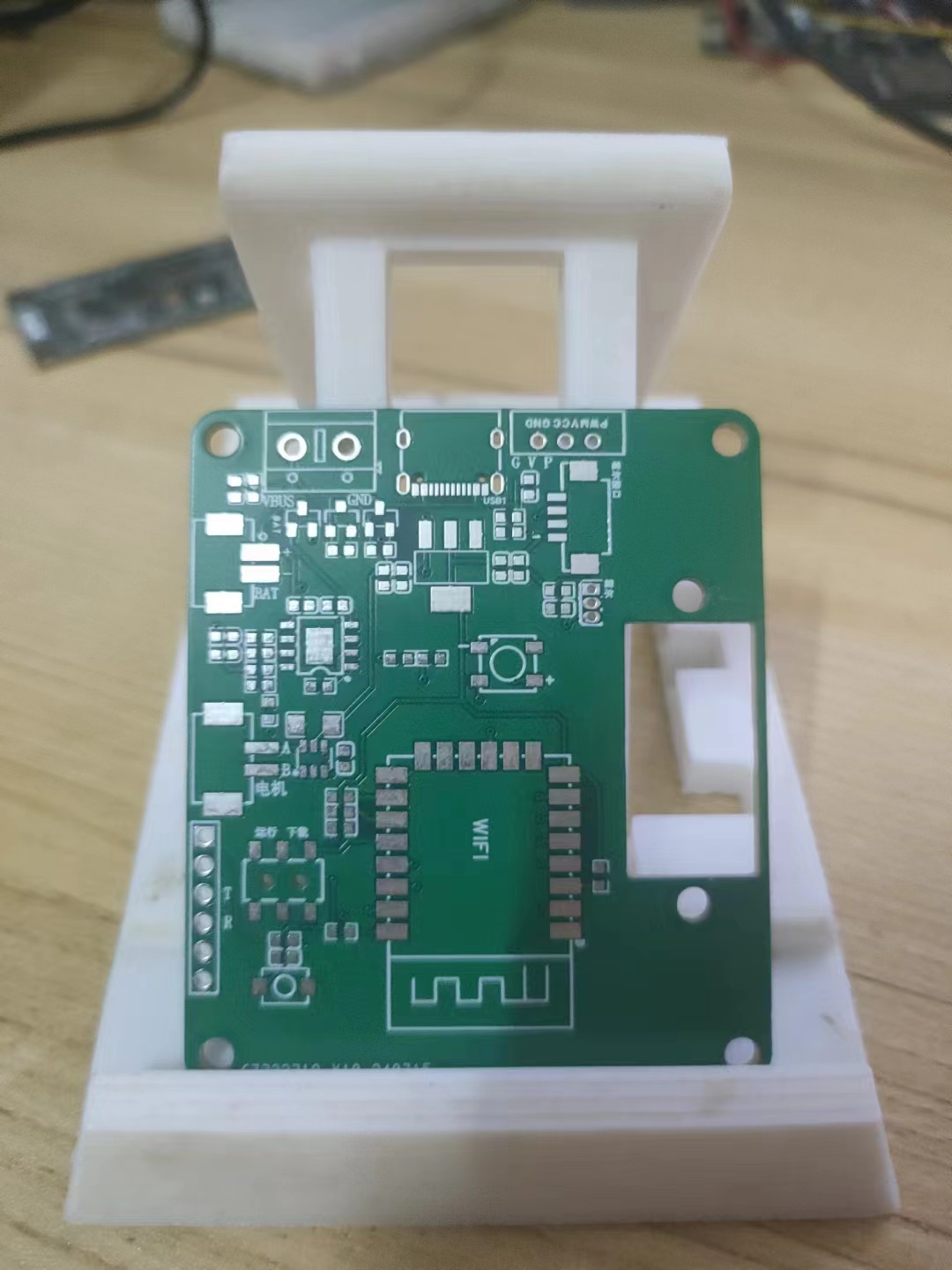
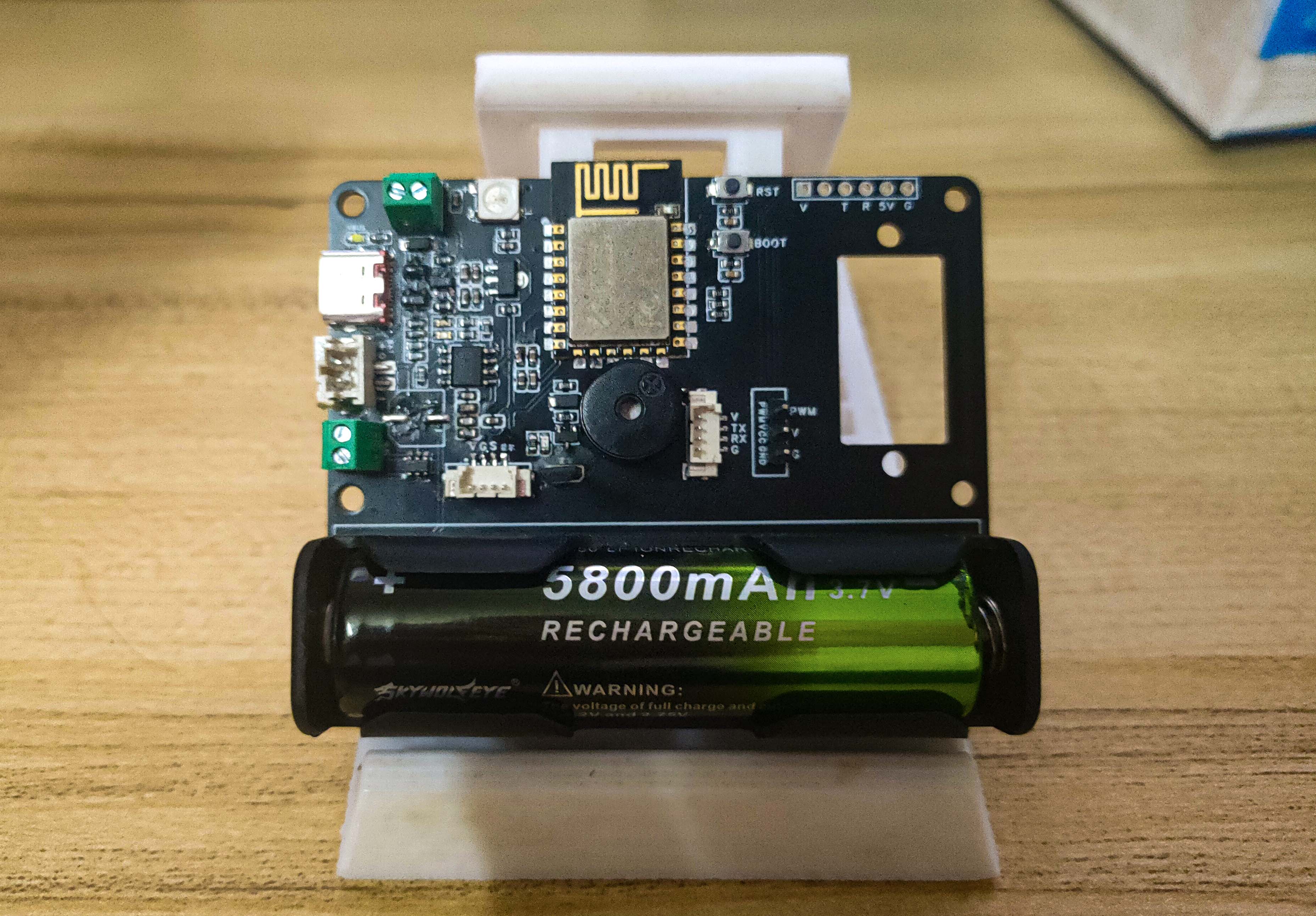
1. It has an automatic dual power supply function, switching between USB power and battery. The main power is USB, and the secondary power is battery. This mainly handles unexpected USB power failures or outages. (Even during a power outage and without internet access, you can use your phone's hotspot to connect to the module and open the door). In addition to the Type-C data cable power interface, the USB power interface also has a screw-type interface to prevent issues with insufficient cable length; you can use a spare 5V 1A charger and data cable for power.

Power consumption: Standby current is 24mA to 43mA, and the average power consumption is 0.17W. Further optimization of the ESP8266's power consumption can achieve even lower power consumption.
2. It features an automatic battery charging circuit using the commonly used TP4056. The charging enable pin is pulled down by default, preventing charging upon power-up; however, a pull-up IO pin can be configured for charging. The ESP8266's ADC measures the battery voltage, and automatic charging thresholds and manual charging initiation can be set.

3. It supports an H-bridge motor driver IC, with sufficient power to drive most brushed motors. It supports forward/reverse rotation, braking, and PWM speed control (this IC is often offered with special discounts on the LCSC online store).

4. A Hall sensor interface is provided, allowing external Hall sensors to be connected to the edge of the door, with magnets placed on the door frame to detect the door's open/closed status. (Any Hall sensor will do, as long as it doesn't have a latching function)
(The Hall sensor function has been verified, but I didn't place it on the edge of the door; I only verified it on the onboard Hall sensor)

5. Essential RGB, with a reserved WS2812 RGB; (Unused function, under development, I don't know what it's used for)

6. Detect USB power supply status and notify the client promptly upon power failure;

7. Serial port download interface, download running status switch, reset button;
8. The software is not yet complete; only basic functions have been verified;
Preset functions:
1. Remote door opening and door lock sharing; 2.
Add LAN broadcast access to WIFI access method;
3. Record door opening and closing time;
4. Send WeChat message reminder for long-term door closure;
5. OTA upgrade;
Currently, only the basic verification source code is provided (you need to manually modify the Secret Key, wifi ID, and wifi password); then compile and download, based on Arduino ESP8266;
The above is the V1 version description
---------------------------------------------------------------------------------------------------------------------------------------
V2 version has been boarded and functions have been verified......
main.cpp
PDF_ESP8266-based remote door opening multi-functional module suitable for rental houses - simple and straightforward.zip
Altium - A simple and effective ESP8266-based remote door opening module suitable for rental properties. (zip file)
PADS - A simple and effective remote door opening module based on ESP8266 suitable for rental properties.zip
BOM_ESP8266-based remote door opening multi-functional module suitable for rental properties - simple and straightforward.xlsx
93597
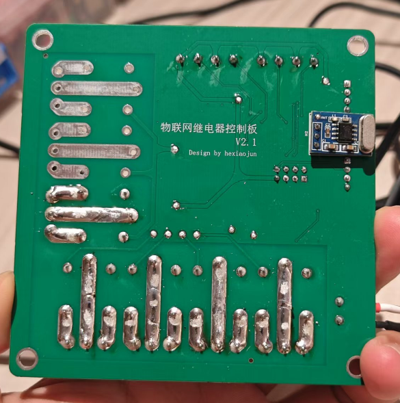
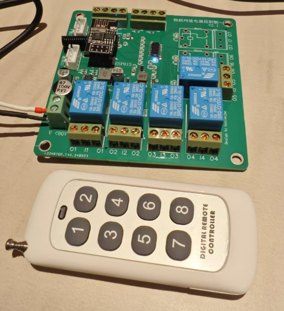
IoT relay control board
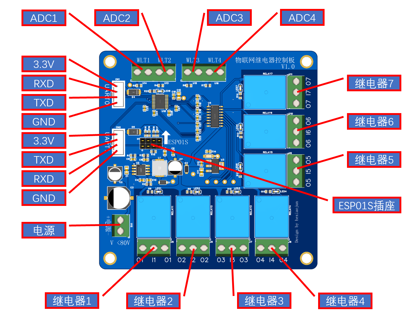
This module uses an STC chip as the main controller, integrating four ADC inputs and seven relays. It supports serial communication control and direct control via ESP01S. It also supports RS433 remote control.
Version 1.1 --> 2.1
adds support for 433 remote control module (SYN480R) .
Version 1.0 --> 1.1 updates include
optimized wiring between some components
, upgraded 3.3V power supply, improved power supply capability for ESP01
, firmware optimization, and support for DHT11 connection .
1. Power
Supply: Minimum voltage 12V, maximum 80V
. 2. Design:
Integrated 4-channel ADC input with 10K pull-down resistors for connecting NTC and other sensors.
Integrated 7-channel relays, allowing selection of normally open and normally closed connections.
Relay control and ADC data reading via serial communication.
Integrated ESP01S docking station for direct internet access.
UART1 and ESP01S cannot be used simultaneously; only one can be used.
3. Firmware:
Firmware is not open source
and lacks a reset button; a flashing program must be connected before powering on.
Firmware is downloaded via UART0.
Join our group to exchange tinkering experiences: 838630818
Relay expansion board firmware flashing tutorial.png
Marquee test firmware.hex
Relay extended firmware b.11.hex
IoT Relay Control Board Communication Protocol 24.11.1601.pdf
PDF_IoT Relay Control Board.zip
Altium IoT Relay Control Board.zip
PADS_IoT Relay Control Board.zip
BOM_IoT Relay Control Board.xlsx
93598
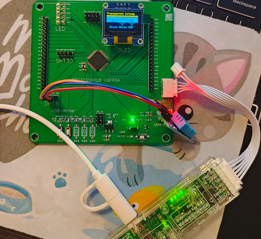
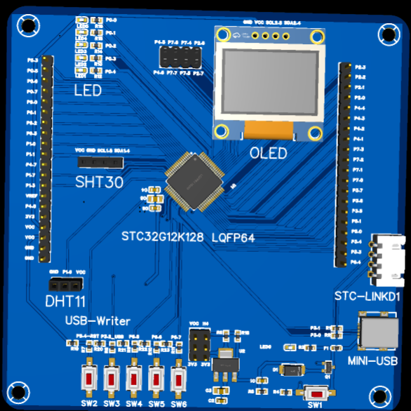
STC32G12K128-LQFP64 Microcontroller Development Board
1. STC32G12K128-LQFP64 core board, reset USB download program, and bring out a 4-pin UART serial port to support STC-LINKD1;
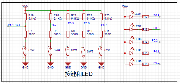
2. Bring out peripherals such as OLED, I2C, OWI, LED and buttons.
I.
Important Anecdote Regarding the STC32G12K128-LQFP64 Microcontroller Development Board: During the initial soldering, the STC32G12K128-LQFP64 was accidentally rotated 90 degrees from its polarity point. After powering on, the LED indicator started flashing, as shown in one of the later videos. After resoldering, the development board functioned normally, indicating the MCU is of good quality. However, a word of caution: while reverse soldering of MCU LEDs looks impressive, rework is a painful process. For components with many pins, always ensure the polarity is correct before soldering. After soldering, at least check the power and ground signals on the PCB to ensure they are not short-circuited before powering on. This will at least prevent combustion or explosion.
The STC32G12K128-LQFP64 core board supports the STC USB Writer, allowing you to connect to a computer via the MINIUSB interface without a USB-to-serial chip like the CH340. Press SW1 and SW2 simultaneously, then release SW1 and then SW2. Use the STC USB Writer in the official STC stcai-isp software to download programs to the development board.
It also features a 4-pin UART serial port supporting the official STC-LINKD1 download and debugging tool, utilizing the STC MCU's built-in crystal oscillator circuit, saving on external circuitry.
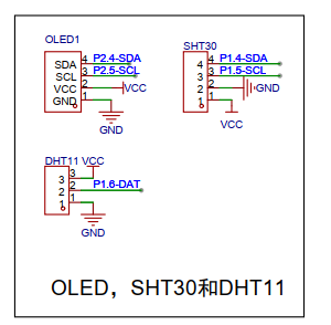
A 0.96mm OLED I2C interface is also provided for convenient program debugging and display on the screen. The GPIO pins have pull-up resistors, so SCL and SDA don't need additional pull-up resistors.
The I2C two-wire connection is to the SHT30, and the single-wire OWI interface is to the DH11, facilitating comparison and learning of the component principles of I2C and OWI communication.
LEDs and buttons are also brought out, and other pins are connected to headers.
1. This was my first time participating in an event hosted by JLCPCB EDA and STC. I wasn't very familiar with JLCPCB EDA operations before.
Seeing that the STC32G12K128-LQFP64 has a built-in crystal oscillator and abundant GPIO resources, and that these GPIO resources, in addition to commonly used software configurations, also have built-in pull-up resistors, these two aspects alone save a lot of external circuitry requirements for crystal oscillators and pull-up resistors. It also supports the STC USB Writer, allowing program download to the MCU without needing serial chips like the CH340.
Wanting to experience the convenience of JLCPCB EDA and the latest features of STC MCUs, I chose to participate in the microcontroller track based on my needs.
III. Design Summary
1. Having decided on the microcontroller track, I decided to create my own development board;
2. The design mainly implements the content in the introduction of the SSTC32G12K128-LQFP64 microcontroller development board, plus example programs.
IV. Hardware Circuit Composition
1. USB download and STC-USB Link1D download circuit as shown in the figure below. First, I used the MINIUSB interface that I had on hand for power supply and to bring out the P3.0 and P3.1 serial ports (according to the official manual, add two 33ohm resistors). This interface is easy to solder and durable. A 6V 0.5A self-resetting fuse, a slow power-off circuit, and a power indicator light are added. According to the STC MCU manual, SW1 and SW2 are used to implement the MCU download program of STC USB Writer;

2. Add a 5V to 3.3V LDO circuit as shown in the figure below to achieve 3.3V power supply. The development board defaults to shorting R18 with solder and directly powering the STC MCU with 5V;

3. The MCU connection uses the package from LCSC, bringing out the corresponding pins.

4. OLED, SHT30, and other I2C pins are brought out. SCL and SDA do not have pull-up resistors. Use the STC MCU program to configure the GPIO to add pull-up resistors, or use the pull-up resistors of the I2C module. When connecting, you need to confirm the actual peripheral circuit of the module; the positioning holes use the M3 screw holes of LCSC EDA;
5. All other unused pins are brought out as shown in the figure below

; 6. The PCB uses a 10*10cm layout with positioning holes. The design simulation diagram is as follows.
V. Program Flowchart
1. The program mainly implements the LED flow test of the 5 GPIOs P0.0 to P0.4;
2. Then, the serial port prints the temperature and humidity of DHT11 10 times;
3. Finally, the OLED interface loops to demonstrate the U8G2 example ported by STC.
Note: The above example program is shown in the video area. The code is attached.
VI. Demonstration Videos
1. One video shows an STC MCU with its polarity point rotated 90 degrees and directly soldered onto the PCB. After powering on, the LEDs immediately started flashing. I wondered if the STC MCU purchased from LCSC came with a built-in test program? Connecting it to the company computer's USB port revealed that the MCU wasn't recognized (before powering on, I checked with a multimeter and the development board's power and ground weren't short-circuited). I then discovered that the MCU wasn't soldered with the correct polarity point.
2. The second video shows the actual effect of the example program after the STC MCU was resoldered correctly.
VII. Attachments
Attachment 1: Example Program
MCU soldering reversed 90 degrees.mp4
Example program video.mp4
Sample program.zip
PDF_STC32G12K128-LQFP64 Microcontroller Development Board.zip
Altium_STC32G12K128-LQFP64 microcontroller development board.zip
PADS_STC32G12K128-LQFP64 Microcontroller Development Board.zip
BOM_STC32G12K128-LQFP64 Microcontroller Development Board.xlsx
93599
DC voltage and current meter
This is a DC voltage and current meter designed based on the STC8H microcontroller and BH45B1225. It overcomes the limitation of ordinary multimeters that lack data output (Modbus), and can simultaneously measure voltage and current and calculate power. It is compact and battery powered.
0. Introduction:
The initial design purpose was to facilitate continuous current and voltage testing and output recording to a computer. The main goal was to facilitate development and testing.
Regarding accuracy, the system consists of two parts: a sampling front-end and a back-end processing unit
. The sampling front-end is extremely rudimentary, mainly for functional verification, and there is still considerable room for optimization (when floating, the current range has a baseline but fluctuates; the voltage range has a baseline and is relatively stable; the zero-value can be set separately via the Modbus interface).
The back-end uses the BH45B1225, mainly because it is easy to purchase, reasonably priced, and has a continuously adjustable PGA (1~128).
1. Measurement Parameters
: Measurable DC voltage ≤24V, DC current ≤1A (resistance voltage divider 1:101, current sampling resistor is 10mR).
In the code, the voltage range using 8 times the PGA can measure 2500/8 = 312.5mV, and the current range using 128 times the PGA can measure 2500/128 = 19.53125mV.
Combining the above measurement ranges with the voltage divider or sampling resistor, the actual voltage input range is ≤31V, and the current input range is ≤1.9A.
The voltage resolution is approximately 0.12mV (currently there is no range division mechanism, calibration is troublesome), and the current resolution has not yet been tested with instruments.
2. Function Introduction: 1.
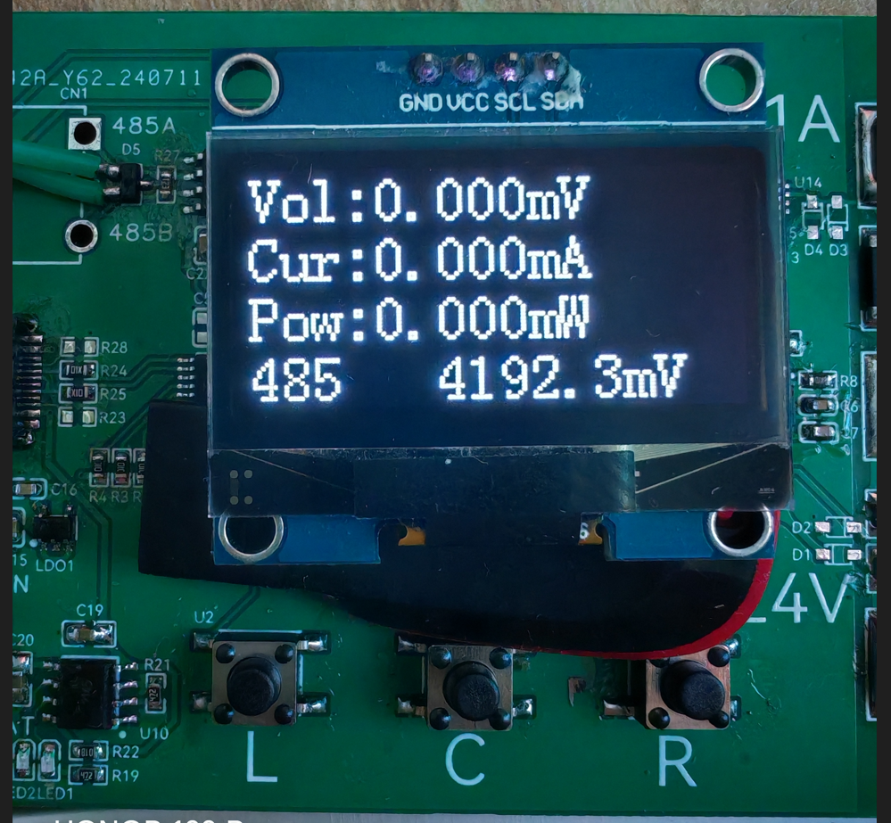
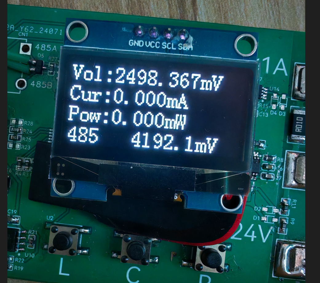
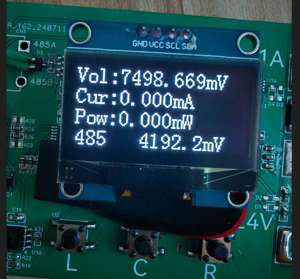
485 Mode ("485" is displayed in the lower left corner of the screen; long press "L" to switch to this interface; this is the default interface after power-on).
In this mode, the screen displays... The first mode displays voltage, current, "instantaneous" power, and battery voltage, with an approximate update frequency of 3Hz.
External devices can access the device's time, measured values, calibration parameters, etc., via a 485 interface based on the Modbus protocol.
This mode is suitable for simple voltage and current testing or for use in embedded user devices.
2. Log Mode (displayed in the lower left corner of the screen; long press "C" to switch to this interface).
In this mode, the screen sequentially displays voltage, current, "instantaneous" power, and battery voltage, with an approximate update frequency of 3Hz.
External devices actively report time and measured values to the 485 port, with an approximate update frequency of 1Hz (reporting format is CSV, convenient for serial port to receive files and form tables).

This mode is suitable for simple voltage and current testing, or for recording voltage and current values to a computer.
3. Settings Mode (displayed at the bottom of the screen) (Press and hold "R" to switch to this interface)
In this mode, the screen displays the voltage calibration value (default 101.000), current calibration value (default 100.000), and battery voltage calibration value (default 5.700)
in sequence. External devices can access the device time, measured values, calibration parameters, etc., via the 485 interface based on the Modbus protocol.

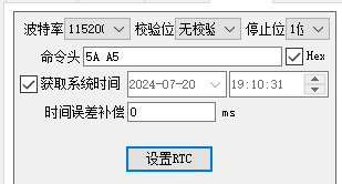
In this interface, you can also use the "RTC Time Synchronization" function in the STC programming software to calibrate the time (tested successfully using stcai-isp-v6.94H).
Let me briefly explain the calibration values. The voltage and battery voltage calibration values are easy to understand. Regarding the current, I'll briefly explain that
the default 100.000 is derived when the sampling resistor is 10mR, but for some reason, when I actually tested the resistor, it only carried 1A of current. The voltage drop across the resistor was measured to be over 12mV,
so I simply reduced the calibration value by about 1.2 times and then fine-tuned it. The final value of 80.989 was found to be acceptable.
Therefore, the calibration value should be adjusted according to the actual resistor size during fabrication.
3.
The Modbus register table is attached, along with a simple user guide.
In Log reporting mode, Modbus commands are not responded to. It is recommended to open the serial port software first, check "Save to file," and then switch to Log mode to avoid losing the CSV header.
When programming, press the "L" button before powering on the chip. The device to be programmed will then appear in the programming software. Programming parameters are in the attached file. (The attached
file contains "ReceivedTofile-COM24-2024_7_21_17-56-47") - "copy.CSV" contains the device's serial port output to the file in Log mode. The measurement object is a lithium battery (not the lithium battery that powers the device; please pay special attention here).
During testing, please note that the 485 pin is not isolated, and the device's power supply should not be introduced into the measurement circuit. When measuring above 24V, pay special attention to electrical sparks; safety first.
4. Simple test

(Bilibili link: Power Measurement Mode).
5. Protocol Description:
Communication Parameters 115200 8N1 only responds to Modbus commands in non-Log mode.
Register Address Table: typedef enum{ AppPort_ModbusReg_Addr = 0, AppPort_ModbusReg_Time_H, AppPort_ModbusReg_Time_L, AppPort_ModbusReg_Voltage_H, AppPort_ModbusReg_Voltage_L, AppPort_ModbusReg_Current_H, AppPort_ModbusReg_Current_L, AppPort_ModbusReg_Power_H, AppPort_ModbusReg_Power_L, AppPort_ModbusReg_Vin_H, AppPort_ModbusReg_Vin_L,
AppPort_ModbusReg_Voltage_ADC_H,//11 AppPort_ModbusReg_Voltage_ADC_L, AppPort_ModbusReg_Current_ADC_H, AppPort_ModbusReg_Current_ADC_L, AppPort_ModbusReg_Vin_ADC,
AppPort_ModbusReg_VoltageGain_H,//16 AppPort_ModbusReg_VoltageGain_L, AppPort_ModbusReg_CurrentGain_H, AppPort_ModbusReg_CurrentGain_L, AppPort_ModbusReg_VinGain_H, AppPort_ModbusReg_VinGain_L,
AppPort_ModbusReg_VoltageDrop_H,//22 AppPort_ModbusReg_VoltageDrop_L, AppPort_ModbusReg_CurrentDrop_H, AppPort_ModbusReg_CurrentDrop_L,
AppPort_ModbusReg_CustomArea_S,//26 AppPort_ModbusReg_CustomArea_E = (AppPort_ModbusReg_CustomArea_S+12),}AppPort_ModbusReg_E;
Address 0: Modbus address, modifiable range 1~247, please do not change to 0, default address is 1 (if the exact address is unknown, send 255, the device will respond accordingly) Addresses 1~2: Current device time, UTC format Addresses 3~4: Voltage measurement value, 1000 times the actual value Addresses 5~6: Current measurement value, 1000 times the actual value Addresses 7~8: "Instantaneous" power estimation value, 1000 times the actual value Addresses 9~10: Battery voltage measurement value, 10 times the actual value Addresses
11~12: Voltage ADC, 18-bit Addresses 13~14: Current ADC, 18-bit Addresses 15: Battery voltage ADC, 12-bit
Addresses 16-17: Voltage calibration value, 1000 times the true value, default 101.000 Addresses 18-19: Current calibration value, 1000 times the true value, default 100.000 Addresses 20-21: Battery voltage calibration value, 1000 times the true value, default 5.700
Addresses 22-23: Voltage zeroing value, 1000 times the true value; measurements less than this value will be zeroed, default 0.5mV Addresses 24-25: Current zeroing value, 1000 times the true value; measurements less than this value will be zeroed, default 1.0mA
Addresses 26-38: Custom boot string, supports '
'Newline, please write a string of no more than three lines, otherwise it will block the boot progress bar
6.
The OLED refresh part uses analog IIC, and for convenience, it uses full-screen refresh, so the above frequencies all use the modifier "approximately".
Regarding the accuracy part, I used 1% conventional resistors in my tests. I feel that the voltage range is okay
, but the current range is not suitable. Regarding the code part, this is my first time using an STC microcontroller, and the code I wrote is really, well, hard to describe. I won't open source it to embarrass myself. If you encounter any problems during the replication, please feel free to give me feedback. In terms of
hardware, I am only a novice and know that there is still a lot of room for improvement. Please give me more guidance.
The measurement reference in the picture is when the air conditioner is on, and the measurement reference in the video is when the air conditioner is off. The temperature drift is quite obvious.
Later, temperature compensation and low temperature drift resistors need to be added. The voltage also needs to be measured in different ranges. The current detection part probably needs to be redesigned, otherwise there is not much meaning to the replication.' After using the STC8H
microcontroller, I feel it's quite good, especially the STC-compatible ISP host computer, which really considers the needs of developers and even the production process.
Of course, there are a few issues. When using STC's single-chip emulation in USB mode at full speed, the computer fan spins wildly, almost like it's about to take off! (Driver version V1.19)
It would be even better if the breakpoints could be switched on and off at full speed and the variable periodic updates could be improved. I look forward to Mr. Yao's update. Even so, I still want to give Mr. Yao a huge shout-out for bringing us so many high-quality and affordable products. To be fair
, LCSC EDA has become increasingly mature over the years, and some features have indeed improved work efficiency. Moreover, they offer two free shipping opportunities every month without any barriers, which is simply a blessing.
I thank STC & LCSC EDA for organizing this event, which allowed me to verify my design ideas. Thank you all for your support.
DVM.hex
Agreement Description.txt
Burning settings.png
ReceivedTofile-COM24-2024_7_21_17-56-47 - Copy.CSV
202407211947.mp4
PDF_DC Voltage and Current Meter.zip
Altium DC voltage and current meter.zip
PADS_DC Voltage and Current Meter.zip
BOM_DC Voltage and Current Meter.xlsx
93601
stc8h8k64u minimum system board
The system board is based on the STC8H8K64U and has all I/O ports reserved.
Since this was my first time designing a PCB, I was worried about download errors, so I included two download methods. There are two USB-micro ports, and I used jumpers to select the download method. The download method shown in the video uses the chip's built-in analog download mode. I used a button to set port P32 to 0; then I pressed the button to power the chip, and downloading began. Actually, you only need to select one download method, but I drew both to avoid problems.
408d08d66379dd9160e0d48d2083bebb.mp4
PDF_stc8h8k64u Minimum System Board.zip
Altium_stc8h8k64u minimum system board.zip
PADS_stc8h8k64u minimum system board.zip
BOM_stc8h8k64u Minimum System Board.xlsx
93602
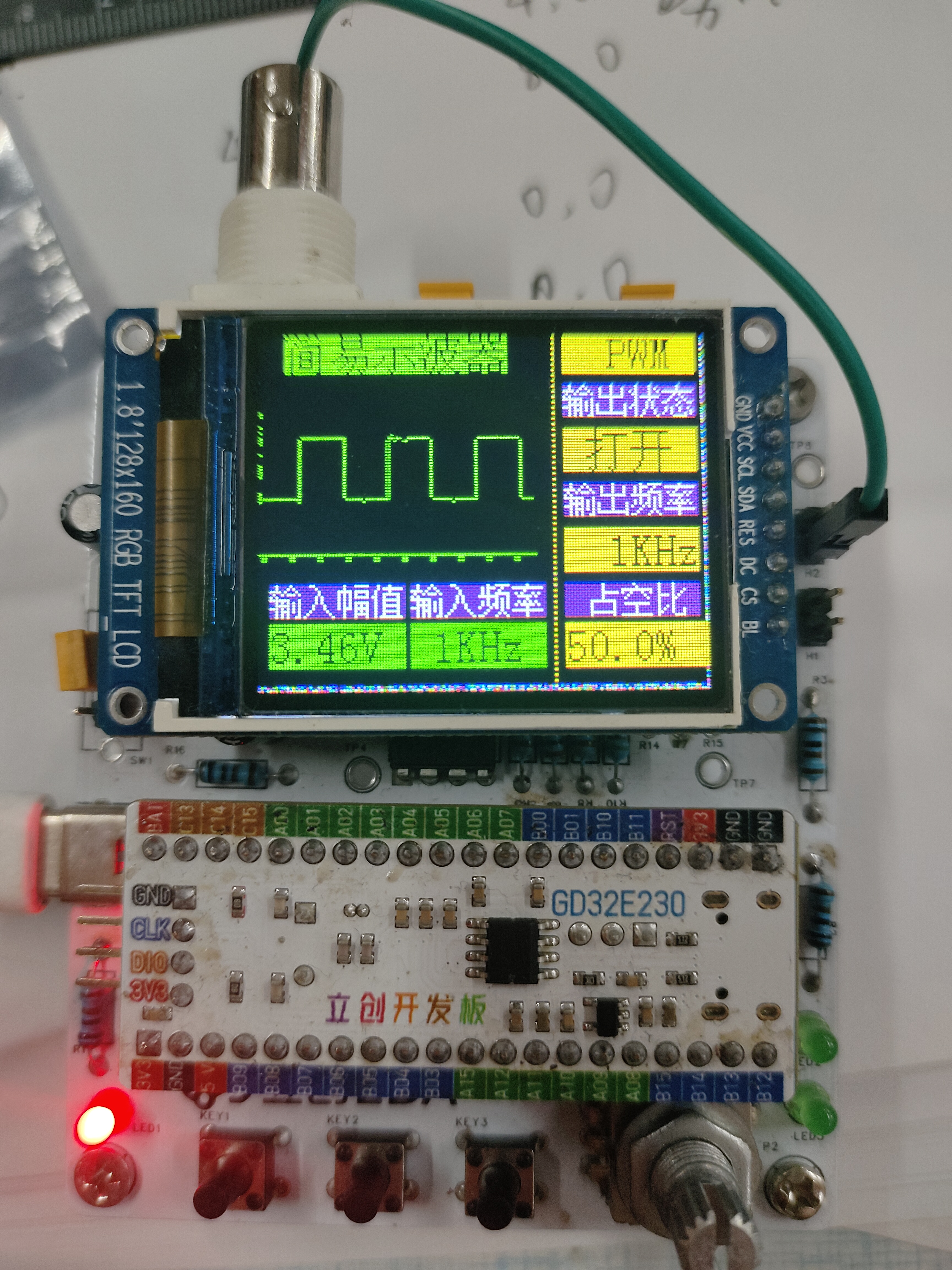
#Bootcamp# Building an Oscilloscope 6713356A based on GD32
Oscilloscopes are essential tools for electronic engineers. They are divided into two types according to the different signals they transmit: analog oscilloscopes and digital oscilloscopes. Analog oscilloscopes use analog circuits and electron guns. Modern oscilloscopes use technologies such as high-speed ADCs and FPGAs, and have the characteristics of high bandwidth, high sampling rate and deep memory depth.
The power supply
for this project uses the GD32 minimum system board as its core, which has an onboard 5V to 3.3V step-down circuit. Therefore, only a 5V power input circuit needs to be designed when designing the expansion board. Following the official training camp, the mainstream Type-C interface was selected. The front-end analog circuit uses a TL074 dual operational amplifier, powered by +5V and -5V. The -5V voltage is generated by an XD7660 chip. Because a diode is connected at the output for protection circuitry, and the diode has a fixed voltage drop, the output voltage is between -4V and -5V.
A basic concept of operational amplifiers
: Virtual open circuit:
The input impedance of an ideal op-amp is infinite, but the input impedance of a real op-amp is finite. If a voltage is applied to the input of the op-amp and the current is measured, the current reading will be close to 0, giving the impression that the op-amp is internally disconnected and no current is flowing in. However, it is actually connected. This phenomenon is called a virtual open circuit.
It can also be understood using Ohm's law: when the voltage is constant, the current is inversely proportional to the resistance. If the resistance is infinitely large, the current will be infinitely small, approaching 0.
Virtual Short:
A virtual short phenomenon occurs when an operational amplifier (op-amp) is in deep negative feedback, making the potentials at the two input terminals equal, as if the two input terminals were shorted together. This can be approximated as a short circuit. In negative feedback, a portion of the op-amp's output signal is extracted and fed back to the input terminals. This feedback makes the voltage difference between the two input terminals (positive and negative) approach zero, meaning the voltages at the two input terminals are almost equal. This is because although the two input terminals are not electrically directly short-circuited, due to the negative feedback, the voltages at the two input terminals are almost equal, as if they were short-circuited; hence the term virtual short. Utilizing
the virtual short and virtual open characteristics of operational amplifiers, functions such as voltage following, proportional amplification, and inverse proportional amplification can be achieved. An ADC (Analog-to-Digital Converter) is an electronic circuit whose basic function is to convert continuously changing analog signals into discrete digital signals. This conversion process is crucial for modern electronic devices to process real-world physical quantities (such as temperature, sound, and light), because digital signals are easier to process, store, and transmit in computers and microprocessors. The working principle of an ADC can be summarized in the following key steps: Sampling: In this stage, the ADC periodically checks the voltage value of the analog signal. According to the Nyquist sampling theorem, the sampling frequency should be at least twice the highest frequency of the input signal to avoid aliasing. This means the analog signal is discretized in time. Holding: After sampling, the holding circuit ensures that the sampled analog voltage value remains constant during the ADC conversion to avoid errors caused by signal changes. Quantization: Quantization is the process of mapping a continuous range of voltage levels to a finite number of discrete levels. Each discrete level corresponds to a digital value. This step introduces quantization error because it involves discarding fractional information. Encoding: Finally, the quantized levels are converted into binary or other digital format codes, which is the ADC output. Common encoding methods include binary encoding and Gray code. Different ADC types (such as SAR ADCs, ΔΣ ADCs, pipeline ADCs, etc.) use different methods and techniques to implement these steps, but the basic principles are the same. For example, a SAR (Successive Approximation Register) ADC approximates and determines the final digital value by comparing the input signal with an internally generated reference voltage; while a ΔΣ (sigma-delta) ADC employs oversampling and noise shaping techniques, first significantly oversampling the signal and then removing noise through digital filtering to achieve high-resolution conversion. The code snippet is entirely based on JLCPCB's open-source example; please refer to the attached physical diagram.
IMG_20240720_161512.jpg
IMG_20240720_161831.jpg
IMG_20240720_161846.jpg
IMG_20240720_161540.jpg
Simple Oscilloscope - Final Case.zip
PDF_#Training Camp# Building an Oscilloscope Based on GD32 6713356A.zip
Altium_#Training Camp# Building an Oscilloscope Based on GD32 6713356A.zip
PADS_#Training Camp# Building an Oscilloscope Based on GD32 6713356A.zip
BOM_#Training Camp# Building an Oscilloscope Based on GD32 6713356A.xlsx
93604
USB docking station + SD card reader
This USB hub and card reader are combined in one, with USB 2.0 speeds.
The USB hub and card reader are combined; just use M2 screws, 8mm long.
PDF_USB Dock + SD Card Reader.zip
Altium USB Dock + SD Card Reader.zip
PADS_USB Dock + SD Card Reader.zip
BOM_USB Dock + SD Card Reader.xlsx
93605
electronic


 京公网安备 11010802033920号

 EP9910-16A


