The power supply
for this project uses the GD32 minimum system board as its core, which has an onboard 5V to 3.3V step-down circuit. Therefore, only a 5V power input circuit needs to be designed when designing the expansion board. Following the official training camp, the mainstream Type-C interface was selected. The front-end analog circuit uses a TL074 dual operational amplifier, powered by +5V and -5V. The -5V voltage is generated by an XD7660 chip. Because a diode is connected at the output for protection circuitry, and the diode has a fixed voltage drop, the output voltage is between -4V and -5V.
A basic concept of operational amplifiers
: Virtual open circuit:
The input impedance of an ideal op-amp is infinite, but the input impedance of a real op-amp is finite. If a voltage is applied to the input of the op-amp and the current is measured, the current reading will be close to 0, giving the impression that the op-amp is internally disconnected and no current is flowing in. However, it is actually connected. This phenomenon is called a virtual open circuit.
It can also be understood using Ohm's law: when the voltage is constant, the current is inversely proportional to the resistance. If the resistance is infinitely large, the current will be infinitely small, approaching 0.
Virtual Short:
A virtual short phenomenon occurs when an operational amplifier (op-amp) is in deep negative feedback, making the potentials at the two input terminals equal, as if the two input terminals were shorted together. This can be approximated as a short circuit. In negative feedback, a portion of the op-amp's output signal is extracted and fed back to the input terminals. This feedback makes the voltage difference between the two input terminals (positive and negative) approach zero, meaning the voltages at the two input terminals are almost equal. This is because although the two input terminals are not electrically directly short-circuited, due to the negative feedback, the voltages at the two input terminals are almost equal, as if they were short-circuited; hence the term virtual short. Utilizing
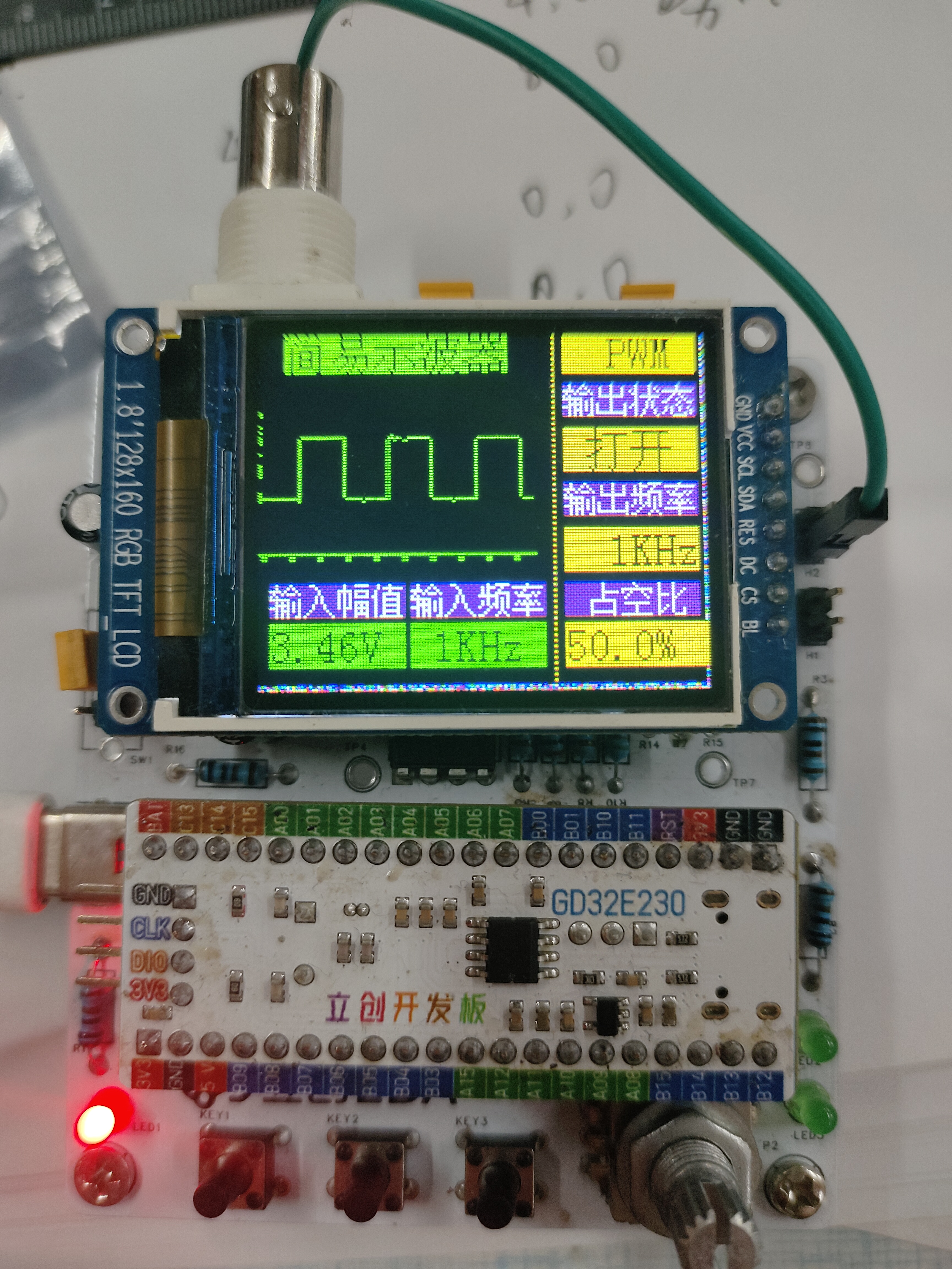
the virtual short and virtual open characteristics of operational amplifiers, functions such as voltage following, proportional amplification, and inverse proportional amplification can be achieved. An ADC (Analog-to-Digital Converter) is an electronic circuit whose basic function is to convert continuously changing analog signals into discrete digital signals. This conversion process is crucial for modern electronic devices to process real-world physical quantities (such as temperature, sound, and light), because digital signals are easier to process, store, and transmit in computers and microprocessors. The working principle of an ADC can be summarized in the following key steps: Sampling: In this stage, the ADC periodically checks the voltage value of the analog signal. According to the Nyquist sampling theorem, the sampling frequency should be at least twice the highest frequency of the input signal to avoid aliasing. This means the analog signal is discretized in time. Holding: After sampling, the holding circuit ensures that the sampled analog voltage value remains constant during the ADC conversion to avoid errors caused by signal changes. Quantization: Quantization is the process of mapping a continuous range of voltage levels to a finite number of discrete levels. Each discrete level corresponds to a digital value. This step introduces quantization error because it involves discarding fractional information. Encoding: Finally, the quantized levels are converted into binary or other digital format codes, which is the ADC output. Common encoding methods include binary encoding and Gray code. Different ADC types (such as SAR ADCs, ΔΣ ADCs, pipeline ADCs, etc.) use different methods and techniques to implement these steps, but the basic principles are the same. For example, a SAR (Successive Approximation Register) ADC approximates and determines the final digital value by comparing the input signal with an internally generated reference voltage; while a ΔΣ (sigma-delta) ADC employs oversampling and noise shaping techniques, first significantly oversampling the signal and then removing noise through digital filtering to achieve high-resolution conversion. The code snippet is entirely based on JLCPCB's open-source example; please refer to the attached physical diagram.


 京公网安备 11010802033920号

 PM10CNJ060


