 Here are some points to note in circuit design
 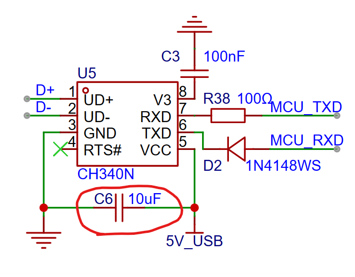 2. CH340's RXD and TXD correspond to the MCU's TXD and RXD. Also, to ensure STC chip cold start, a small resistor needs to be connected in series on the CH340's RXD pin, and a diode in series on the TXD pin. Otherwise, CH340 will supply power to the chip and energize VCC. Actual measurements show that without the resistor and diode, VCC is approximately 3V (power supply is 5V).
  3. For the Type-C interface design, please follow the official documentation specifications (CC1 and CC2 must be connected to a 5.1kΩ resistor before grounding, DP and DN must be connected to a 33Ω resistor before connecting to CH340).
  Some points to note in my circuit design
  Taking the AD conversion code as an example, the following code can be used to read data:
  4. The DAC0832 outputs current. To observe the change in output current, please use a red LED. Do not use green or blue LEDs, as these require a larger current to light, and the DAC0832 may not be able to drive them.
All reference designs on this site are sourced from major semiconductor manufacturers or collected online for learning and research. The copyright belongs to the semiconductor manufacturer or the original author. If you believe that the reference design of this site infringes upon your relevant rights and interests, please send us a rights notice. As a neutral platform service provider, we will take measures to delete the relevant content in accordance with relevant laws after receiving the relevant notice from the rights holder. Please send relevant notifications to email: bbs_service@eeworld.com.cn.
It is your responsibility to test the circuit yourself and determine its suitability for you. EEWorld will not be liable for direct, indirect, special, incidental, consequential or punitive damages arising from any cause or anything connected to any reference design used.
Supported by EEWorld Datasheet
EEWorld
subscription
account

EEWorld
service
account

Automotive
development
community

Robot
development
community

About Us Customer Service Contact Information Datasheet Sitemap LatestNews


Room 1530, 15th Floor, Building B,
No.18 Zhongguancun Street,
Haidian District,
Beijing, Postal Code: 100190
China
Telephone: 008610 8235 0740
 京公网安备 11010802033920号

 RS1/4162R0AE12


