There are two usage modes: you can directly solder it to the notch on the development board using pin headers, which fits very well; or you can solder it together using female headers.
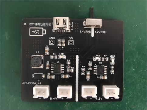
Based on the CS5090EA and TP4056 design, it can charge single-cell 3.7V (4.2V fully charged) and dual-cell series-connected 7.4V (8.4V fully charged) lithium batteries. Safe and reliable.
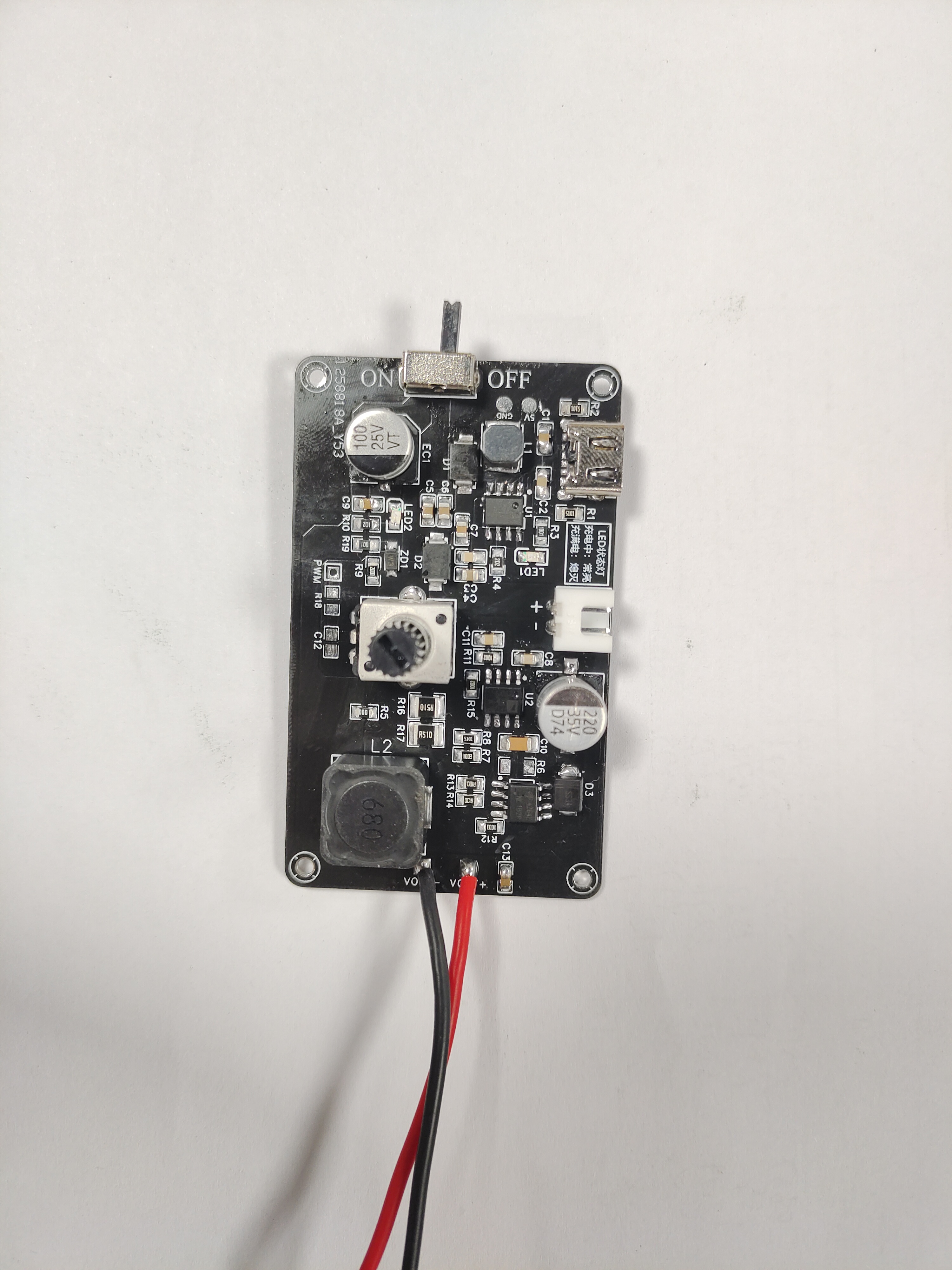
Front of the product:
Back of the product:

---------------------Divider-------------------
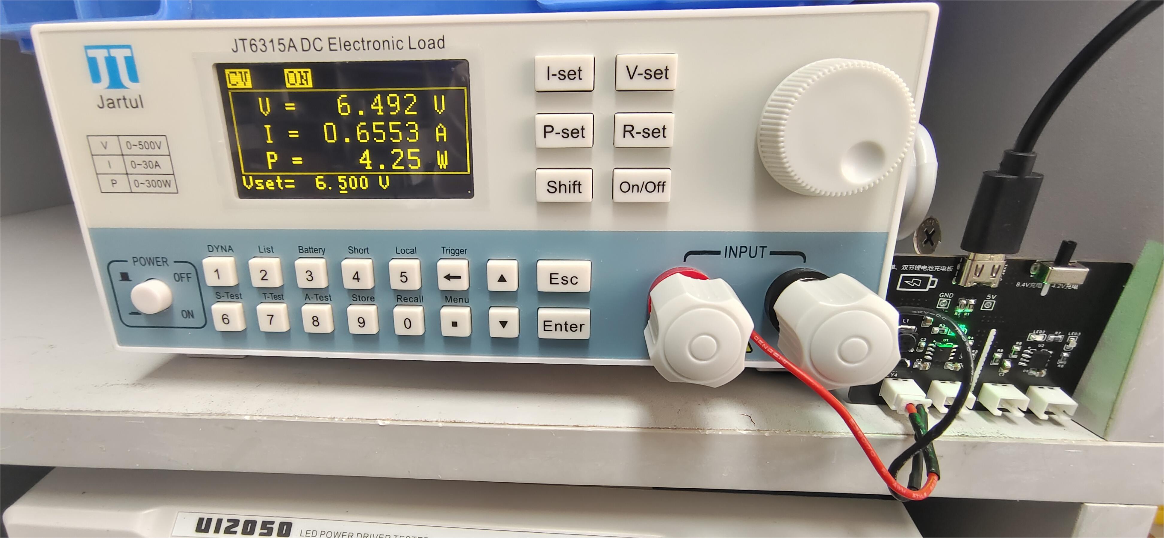
------------Dual-cell series lithium battery charging----------
Battery voltage undervoltage (
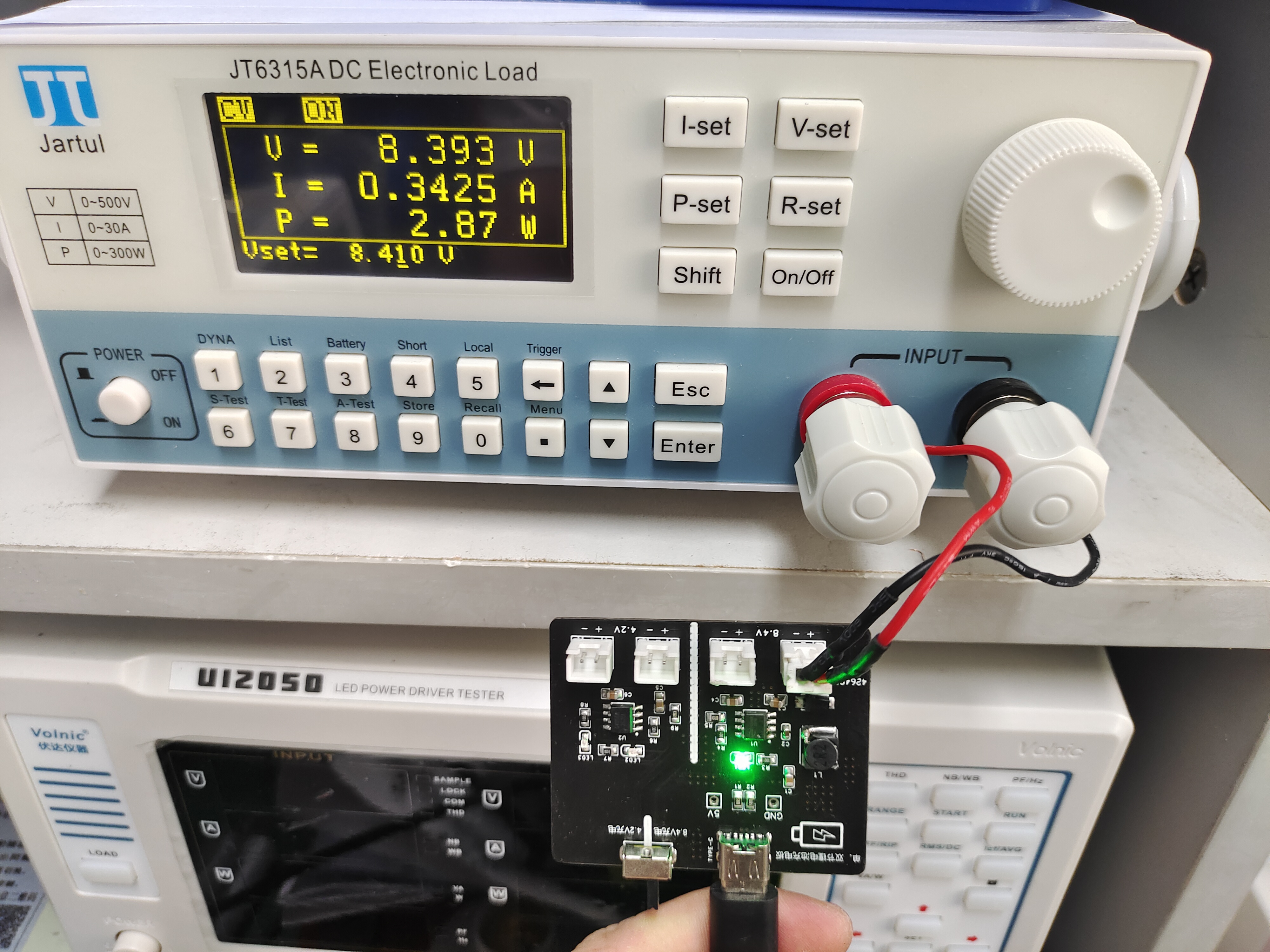
when battery voltage (>5.6V)) - Constant current charging mode:

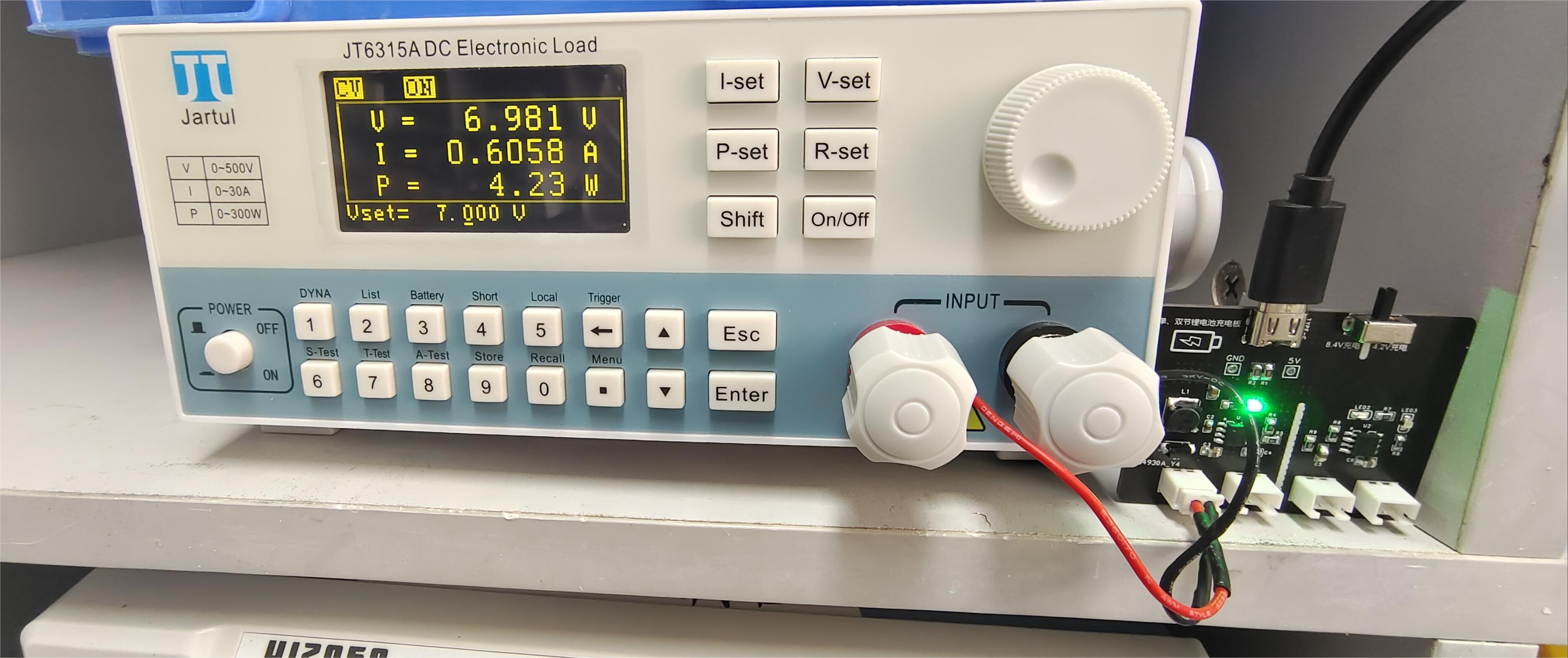
When battery voltage (close to 8.4V) - Constant voltage mode:

When battery voltage is fully charged (8.42V) - Basically no longer charging:

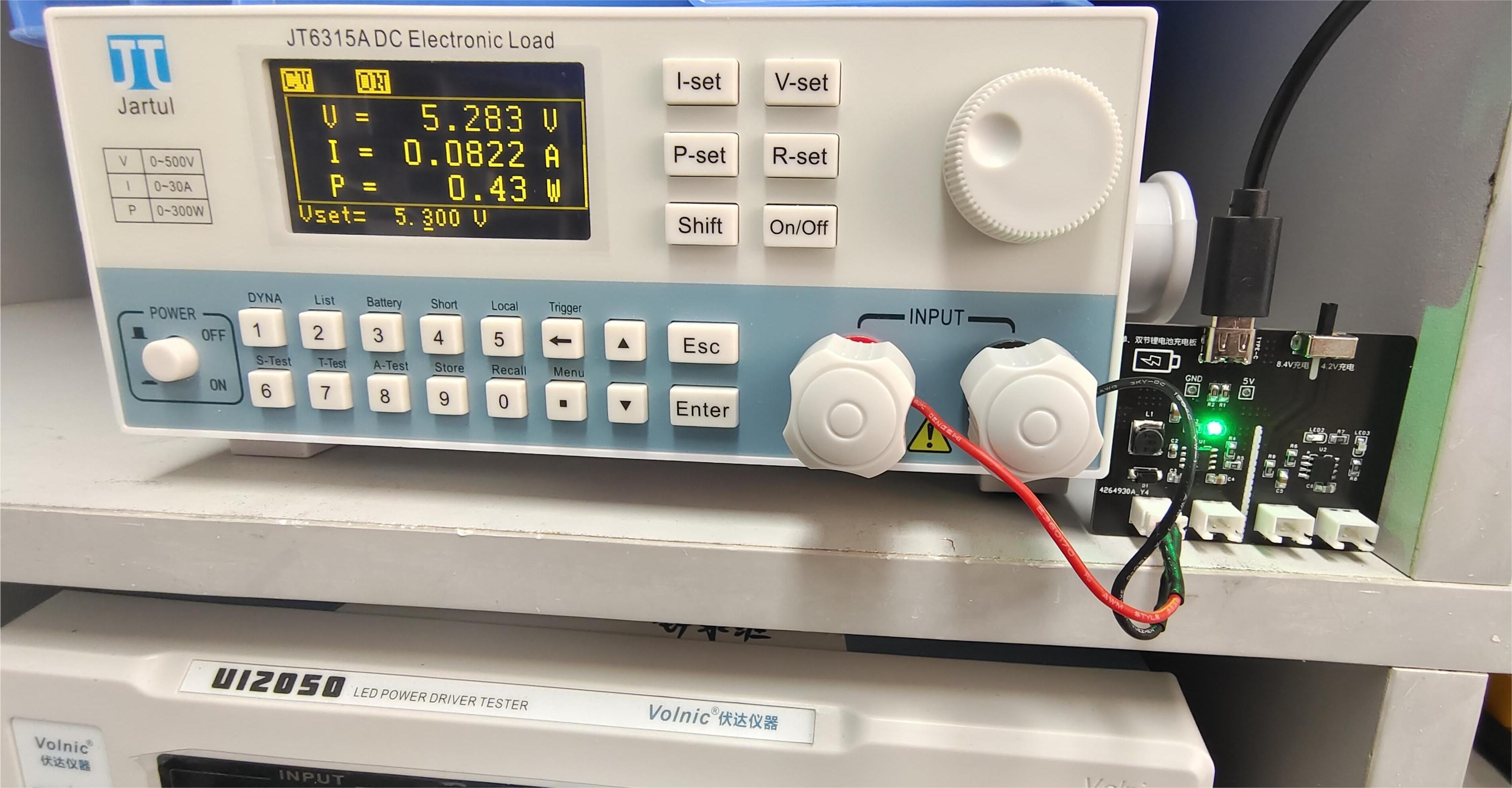
-------------Single-cell lithium battery charging-----------
Battery voltage
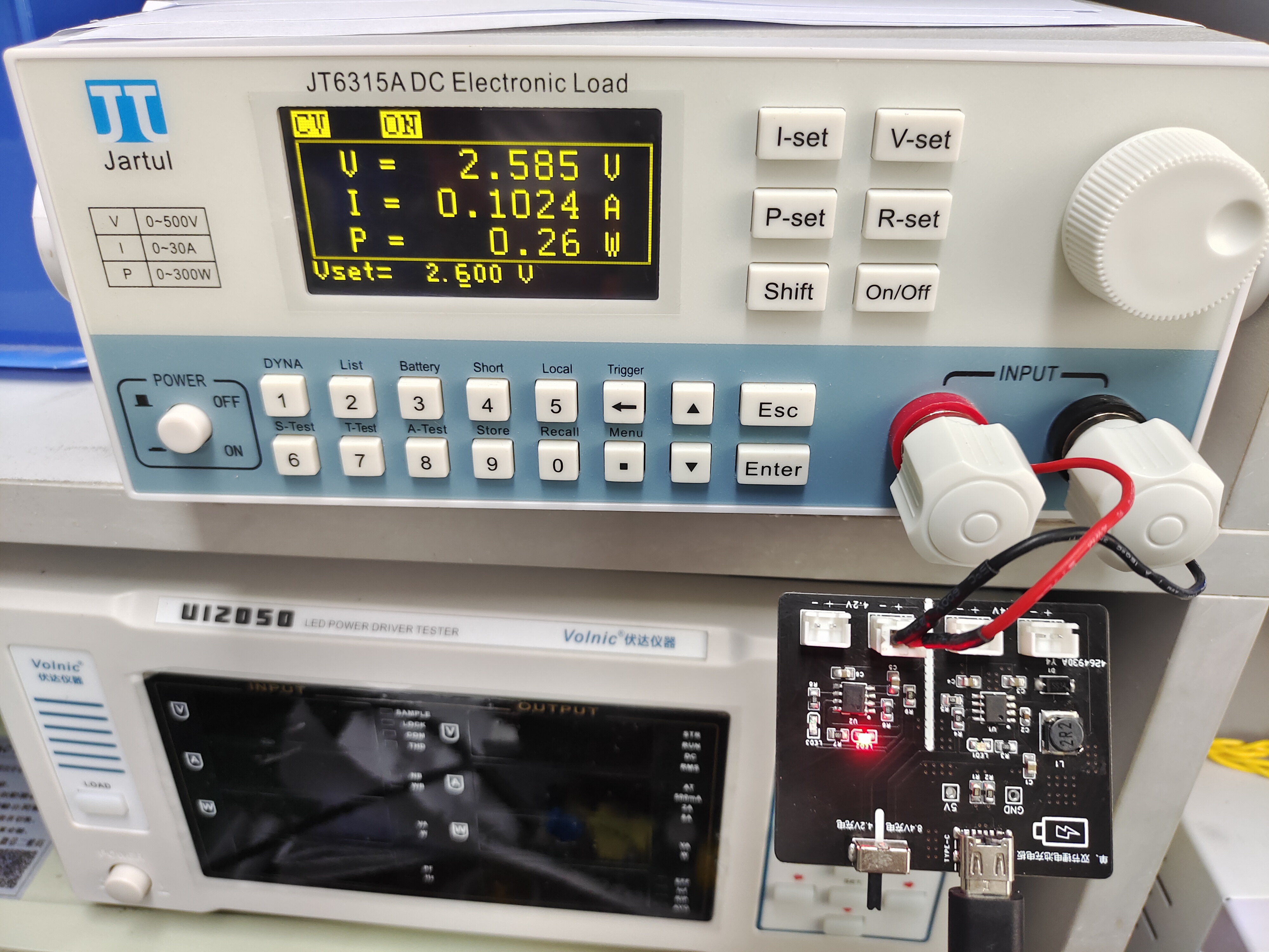
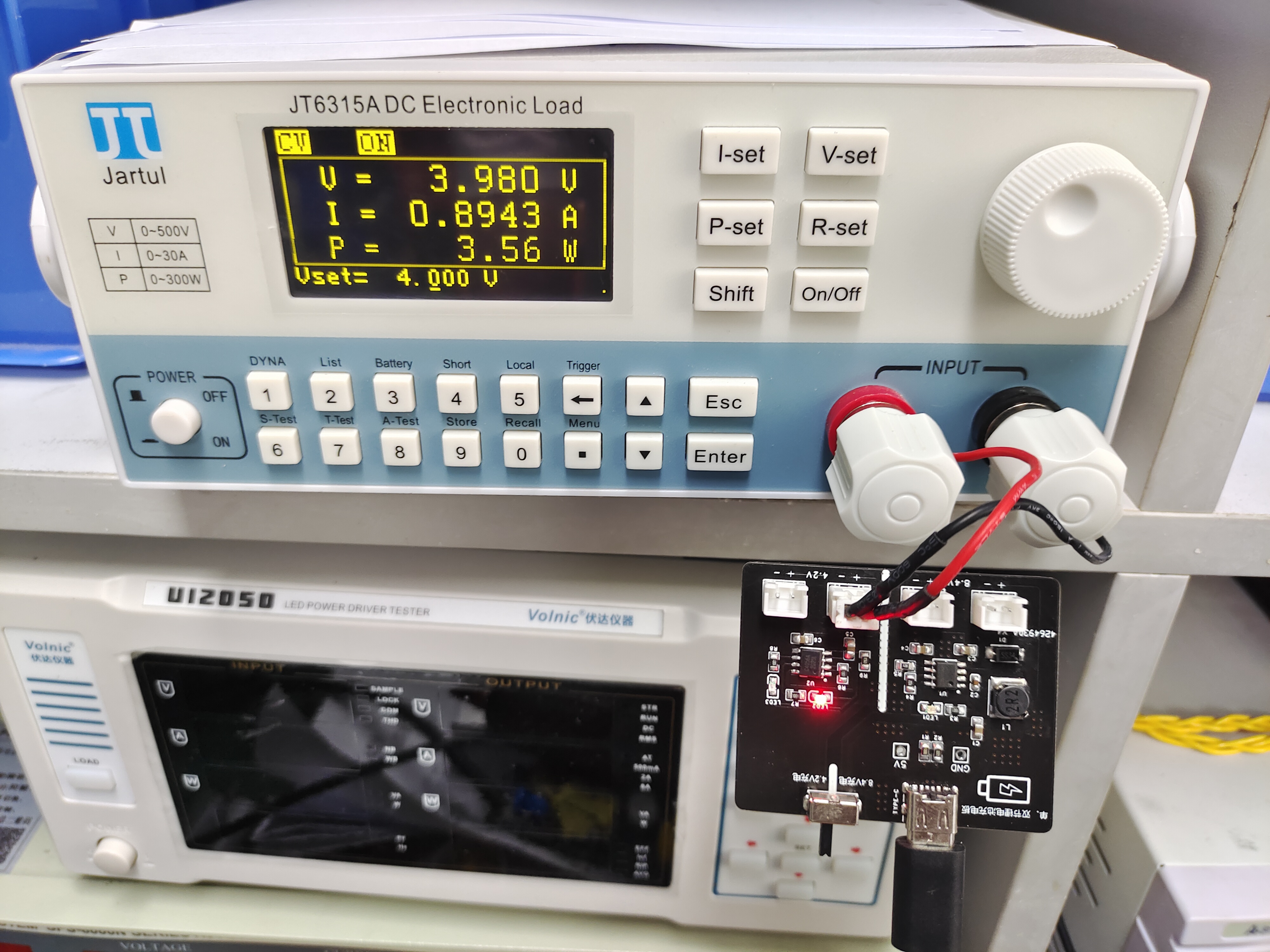
When battery voltage is greater than 2.9V and less than 4.2V - Constant current charging mode:


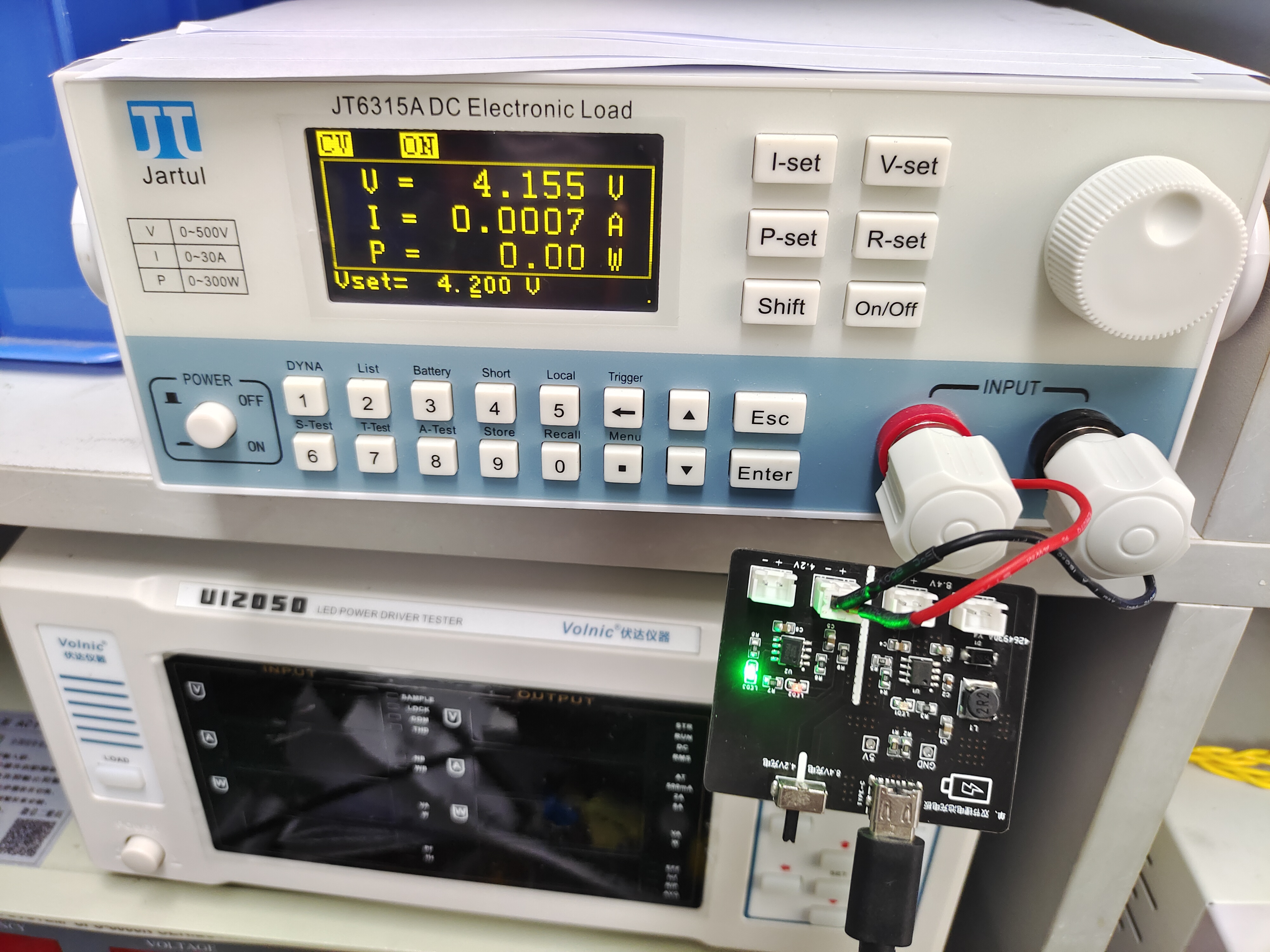
When battery voltage is fully charged (4.2V) - Constant voltage charging mode (basically no longer charging, green light on):
1. This is an LED/DC motor driver module with constant current and charging function (supporting simultaneous charging and discharging).
2. The solution uses a BOOST boost circuit to boost and discharge a 7.4V lithium battery input. The default output can connect to a 9 to 14V load and supports dimming and speed control functions.
The solution uses the CS5090EA and FP7209 circuits.
1. This is an LED/DC motor driver module with constant current output and charging function (supporting simultaneous charging and discharging). 2. The solution uses a BOOST boost circuit for boosting and discharging a 7.4V lithium battery input. The default output can connect to a 9 to 14V load and supports dimming and speed control.
Parameters can be modified; by changing some parameters in the schematic, higher voltage and current can be output. A single lithium battery can also be used for discharging (parameters need to be modified, and charging is not supported).
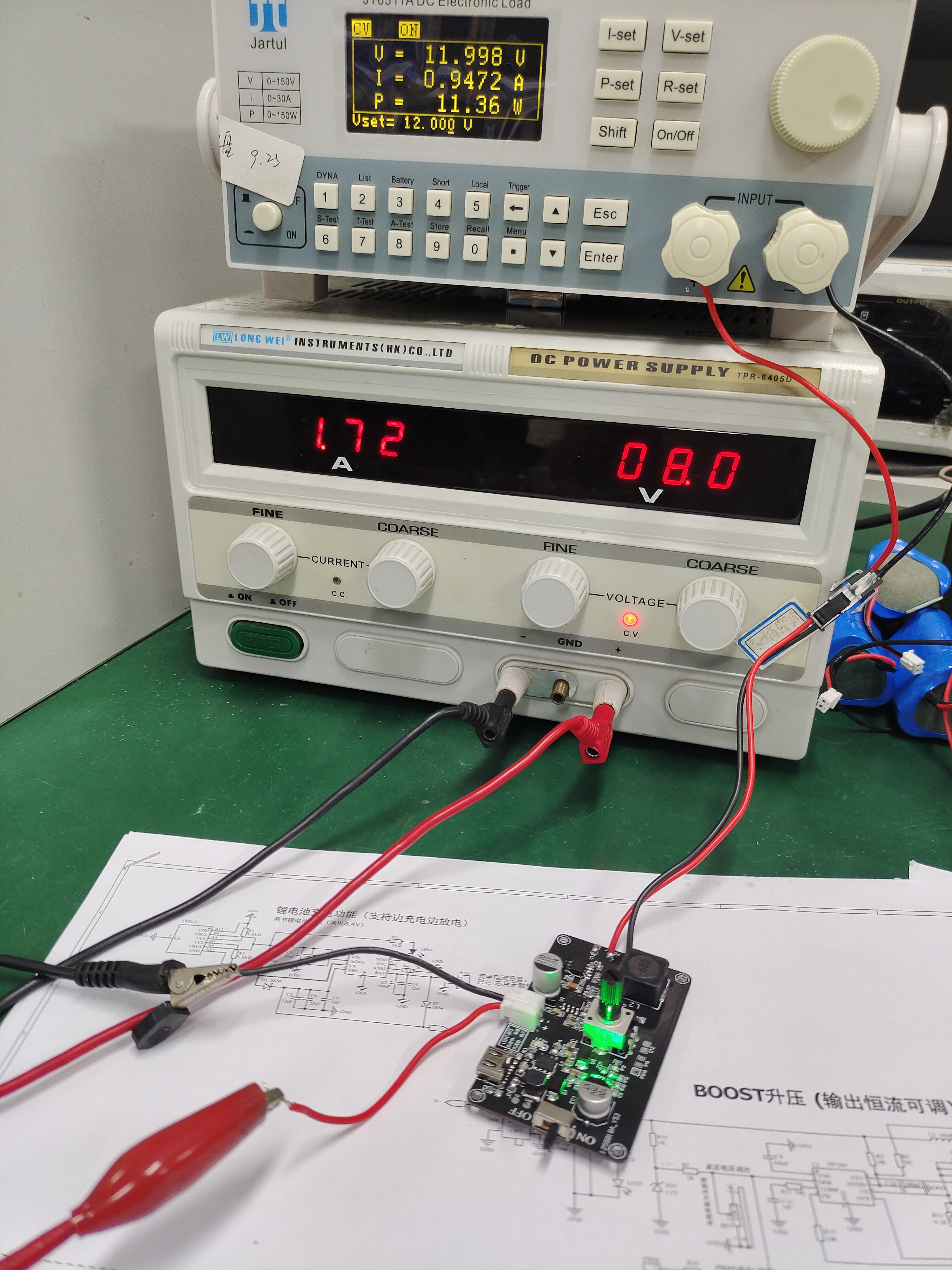
Actual test results: 1 (output 12V, full load):
2 (output 9V, full load):

3 (output 13.95V, full load):
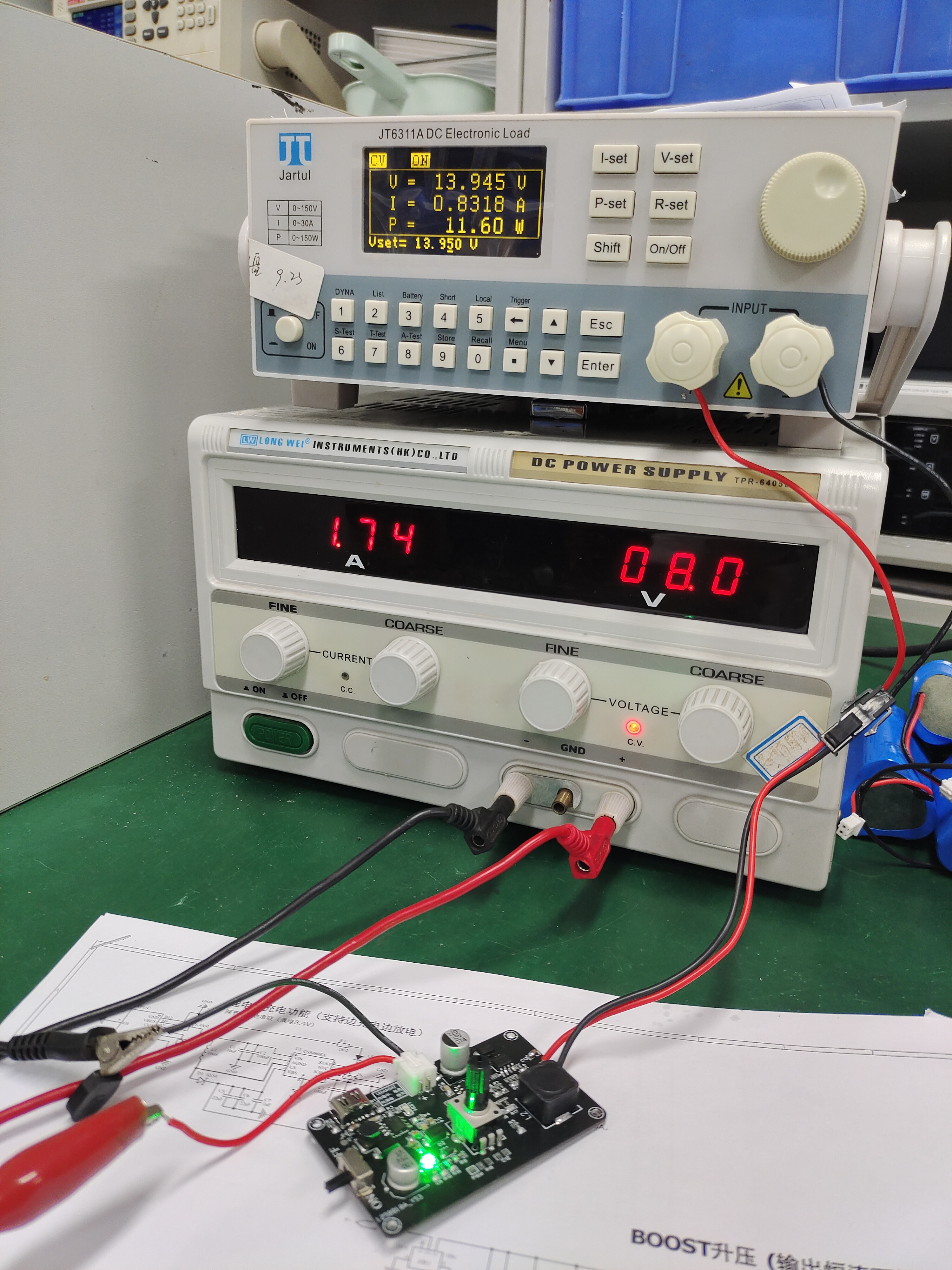
Component temperatures are good, and heat generation is low.
When selecting a load, pay attention to the load's voltage and current capacity and whether it has good heat dissipation conditions.
The attached project file can be imported using the professional version —
BOM (Bill of Materials):

Gerber_PCB_Papermaking_2023-08-08.zip
Project file containing schematic, PCB.epro
PDF_LED, Small Fan Driver Board CS5090EA+FP7209.zip
Altium_LED, small fan driver board CS5090EA+FP7209.zip
PADS_LED, Small Fan Driver Board CS5090EA+FP7209.zip
BOM_LED, Small Fan Driver Board CS5090EA+FP7209.xlsx
93780
AIR001 Minimum System Board
At this point, is anyone still designing the AIR001 board? The AIR001 core board is really small, measuring 2.2cm*2.5cm. It's so small that it doesn't even have pin silkscreen markings, but it does have an automatic download circuit.
This description
is based on the AIR001 from Heze Technology. The schematic? It's the schematic of Heze Technology's official board, which I'm learning from (and copying). The parts in the red box are not generated for the PCB.
Pay attention to the pin header soldering; do it according to your preference.
The other
attachments include two projects, V1 and V2. V1 hasn't been tested on a PCB and doesn't include the download circuit; V2 includes the download circuit, and the programming pins are the same as on the official Heze Technology board. The above refers to V2.
AIR001 core board - mini.eprj
PDF_AIR001 Minimum System Board.zip
Altium_AIR001 Minimum System Board.zip
PADS_AIR001 Minimum System Board.zip
BOM_AIR001 Minimum System Board.xlsx
93781
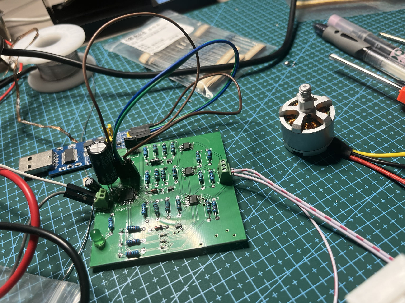
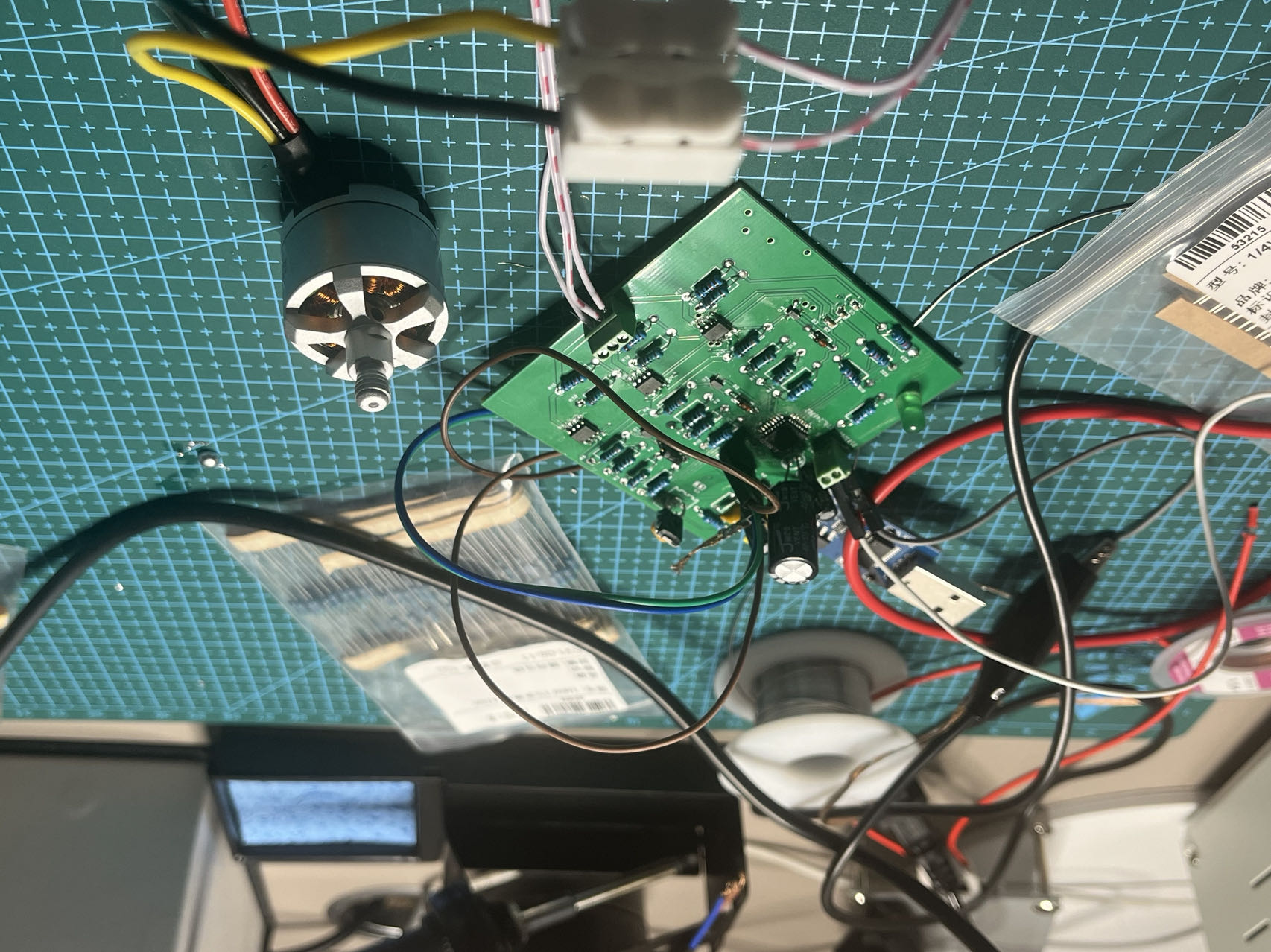
Mid-power ESC verification based on STC8H1K28
This project, originating from https://www.stcaimcu.com/forum.php?mod=viewthread&tid=1822, is primarily based on the STC8H1K28 as the main controller and utilizes potentiometer control for the brushless motor driver board.
This document describes the schematic design
of a BLDC control board based on the STC8H1K28. The schematic mainly includes a test circuit, a brushless motor drive circuit, and a download circuit. The PCB design primarily uses through-hole packages, with some 0603 capacitors (because I didn't want to buy new ones). For downloading, note that I used serial port downloading; serial port downloading on an ISP requires manual power-off. Physical demonstration is also included.
Demo video 1.mp4
Demo video 2.mp4
motor.hex
Three-phase brushless motor drive - STC8H - without HALL.rar
PDF_Mid-Power ESC Verification Based on STC8H1K28.zip
Altium_Mid-Power ESC Verification Based on STC8H1K28.zip
PADS_Mid-Power ESC Verification Based on STC8H1K28.zip
BOM_Verification of Medium Power ESC Based on STC8H1K28.xlsx
93782
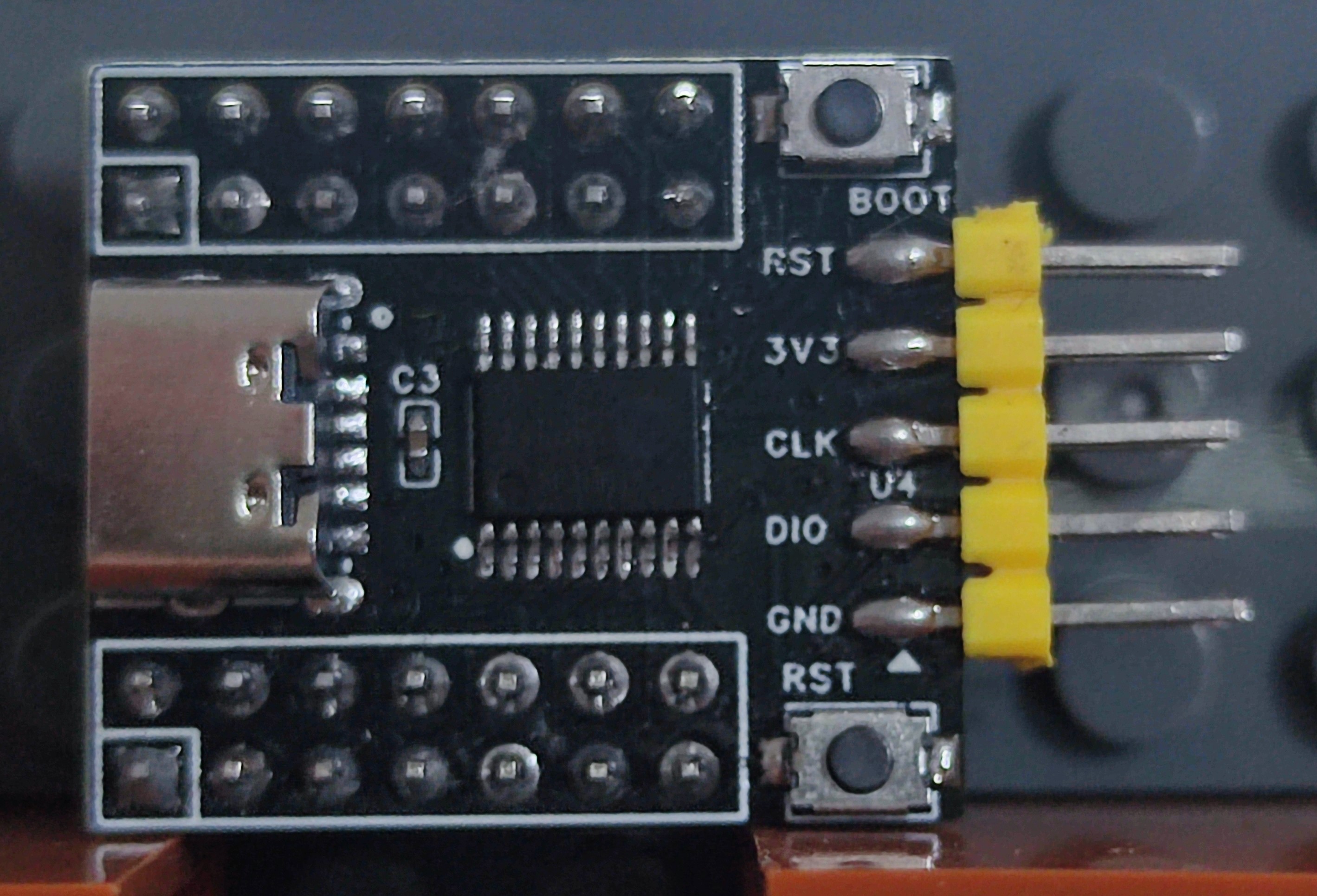
Mini Type-C to TTL converter (with indicator light)
Mini Type-C to TTL converter, based on CH340N, with indicator lights, can be surface mounted to PCB.
This solution is
based on the CH340N design, minimizing the use of other components. Functionally, it features
a Type-C to TTL
converter with indicator lights for power, transmit, and receive.
The GH1.25-4P interface uses
three horizontal 2.54mm header pins (simply horizontally solder a standard vertical header pin).
It has pads on the back, supporting surface mounting on other PCBs (I haven't personally tested this).
Two versions are available: a smaller one and a larger one. The smaller design omits the CC pin pull-down resistor and power decoupling capacitor, yet it still allows surface mounting on other PCBs.
PDF_Mini Type-C to TTL (with indicator light).zip
Altium_Mini Type-C to TTL (with indicator light).zip
PADS_Mini Type-C to TTL (with indicator light).zip
BOM_Mini Type-C to TTL (with indicator light).xlsx
93783
ERCF V2 Rabbit V2 Encoder
ERCF V2 Rabbit V2 Encoder
ERCF V2 Rabbit V2 Encoder
[An open-source encoder suitable for DIY 3D printers, solving problems such as filament breakage, nozzle clogging, and filament entanglement]
Video introduction:
https://www.bilibili.com/video/BV1hS411c7ou/?share_source=copy_web&vd_source=89569af627beea219715fc4ad4927d70
Actual product image:

PDF_ERCF V2 Rabbit V2 Encoder.zip
Altium_ERCF V2 Rabbit V2 Encoder.zip
PADS_ERCF V2 Rabbit V2 Encoder.zip
BOM_ERCF V2 Rabbit V2 Encoder.xlsx
93784
electronic

 However, the official application adds the IP3005A battery protection chip; please add it in actual applications.
  Actual usage

 The code used for learning is the official example code, which can be downloaded from the official forum, or you can also download it using the powerful and versatile tool STC-ISP (in the menu, you can download the instruction manual, code examples, Keil device packages, header files, etc.).
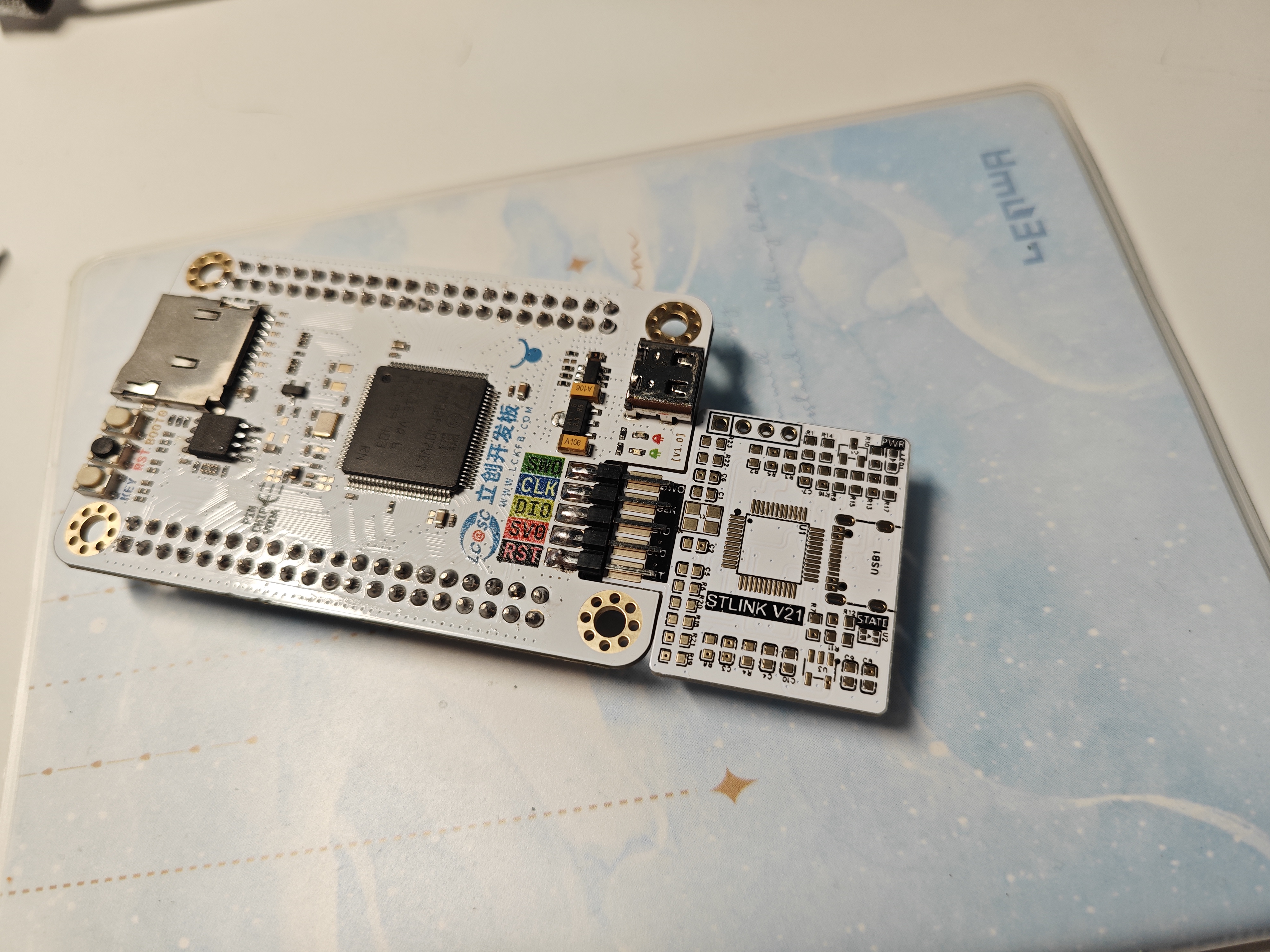


 京公网安备 11010802033920号

 AQV257


