Project Summary:
This is a verified J-LinkV9 based on the open-source project by @Travellium. The schematic has been modified, and the board has been redrawn as a double-sided board for easy customization of silkscreen colors.
Specific hardware changes include:
1. Modifying the 3.3V reference voltage output capability by adding a protected 3.3V LDO output. The isolated version is limited to 300mA, and the through version to 400mA, allowing direct power supply to low-power loads during J-Link debugging.
2. Adding ESD protection to the data interface, and TVS diodes and fuses to the power outputs to minimize the possibility of backflow voltage from the debugged device when used as a through version.
3. Isolating the 3.3V output from the microcontroller's 3.3V power supply to prevent damage to the controller from low-voltage backflow (in reality, genuine 32-bit microcontrollers are quite durable and generally won't be damaged by electrical shock).
4. Integrating the isolated and through versions onto a single board, allowing users to use resistors as jumpers to determine whether to use it as an isolated or through version, thus reducing costs. (However, please note: Since the through-type and isolation types are on the same board, the gap withstand voltage cannot meet the 2.5KV isolation requirement. It is also not recommended to debug microcontrollers related to mains power (such as digital power supplies); the intended application is debugging brushless motor drivers, etc.; otherwise, user safety cannot be guaranteed!!!)
Fabrication and Assembly:
1. Soldering:
1. It is recommended to solder the STM32F205RET6, seven SN74LVC2T45DCRUs, and three ESD diode arrays first. Otherwise, a larger soldering iron tip will be difficult to insert when soldering other components later. It is recommended to use drag soldering for the STM32 and SN74. Other components can be soldered using solder paste + hot plate soldering.
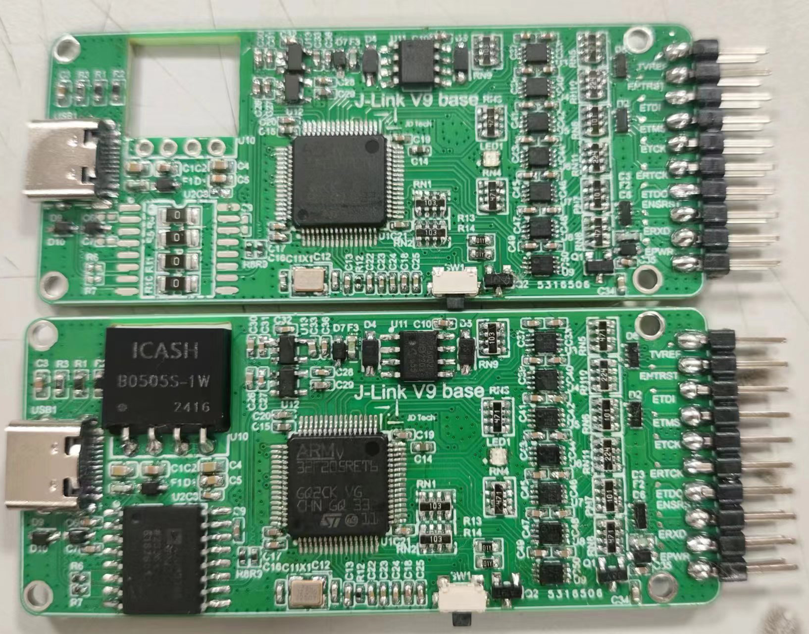
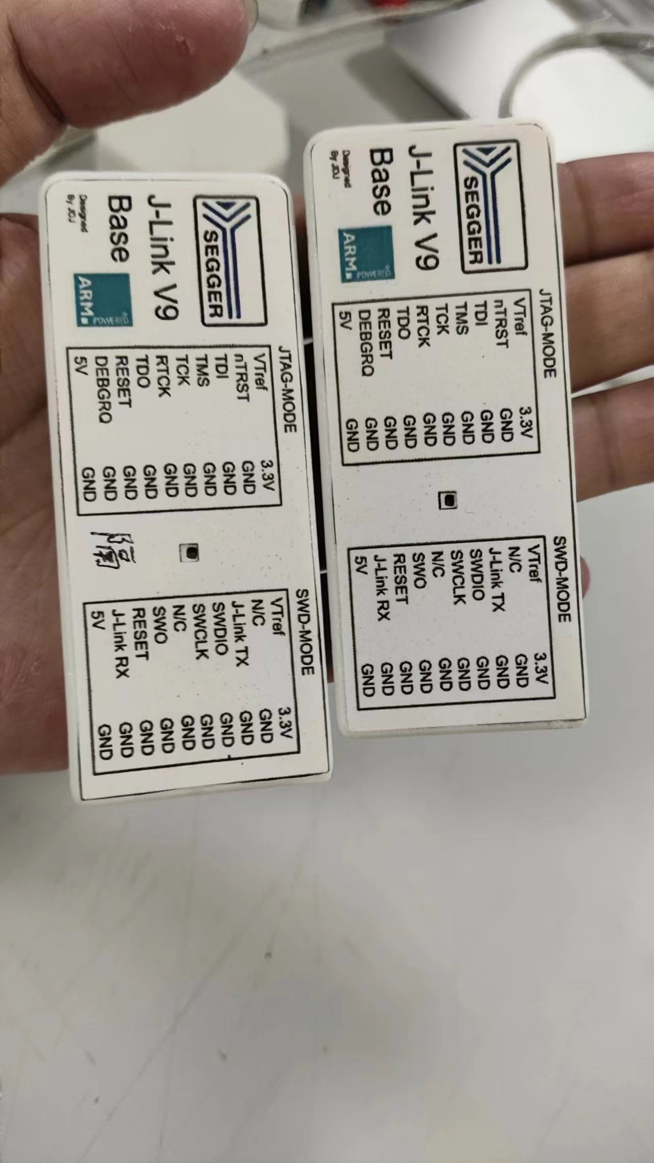
2. If you do not intend to use the ADUM3160, simply solder 0-ohm resistors to the four 1206 resistor pads under the ADUM3160 to short-circuit them. (As shown in the picture, the top is the through board, and the bottom is the isolation board)
3. For the tail pin header, it is recommended to insert the pin header into the socket after printing out the outer shell, and then put the board into the outer shell before soldering. Otherwise, it is easy to solder crookedly (both of mine were crooked).
2. Debugging (important):
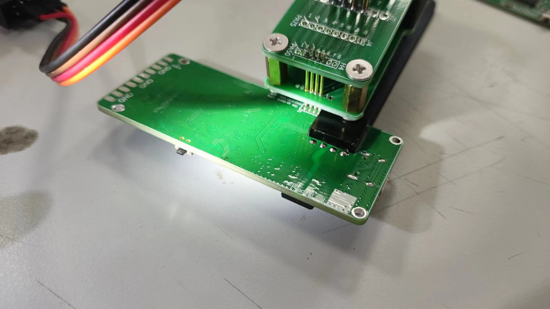
1. After completion, the inside of the chip is empty. It will not be recognized after being plugged in. You need to use the debugging pad reserved in the upper left corner of the board to first burn the bootloader; then plug it into the computer, and use the host computer to flash the firmware. Finally, write the serial number and function.
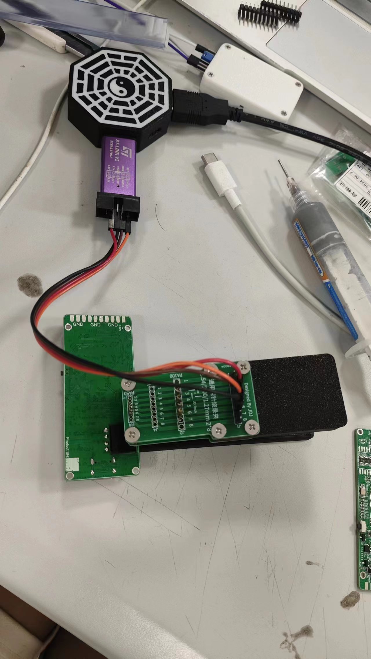
First, burn the bootloader. Use a burning clip (as shown in the picture) or solder to connect 3.3V, GND, SWDIO, and SWCLK to ST-LINK respectively. Open ST-Link Unification or STM32CubeProgrammer, and burn the bootloader.bin file in the attachment into the STM32F205RET6.
There are many online resources detailing the flashing process, so I won't go into detail here (mainly because I forgot to take pictures at the time >﹏<).
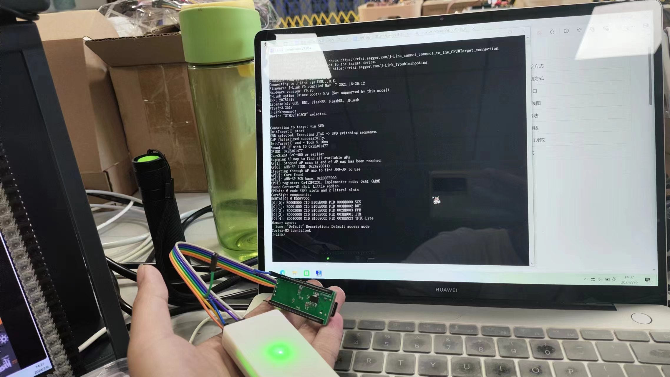
2. Go to SEGGER's official website (here ヾ(•ω•`)o), download the J-Link driver, and install it. Plug the prepared J-Link into your computer (remember to use a multimeter to check for short circuits first). Under normal circumstances, Device Manager should show that the J-Link is connected; then open J-Link Commander.exe in the attachment. It will prompt that the connected J-Link is in bootloader mode and requires firmware flashing to function properly; click Yes, and the firmware will be automatically flashed to the J-Link. After plugging and unplugging again, the J-Link should be recognized normally.
3. Open the J-Link Commander in the attachment and enter the following statements to add functions and write the SN code:
Run the following commands in sequence under the J -Link command
. Please use the SN code from the following links to flash the SN:
Link A
Link B
Do not use the SN in the example, as it will report a clone and cause online debugging and other functions to be unusable.
Exec SetSN=59788888 ; Add SN
Exec AddFeature GDB ; Add GDB
Exec AddFeature RDI ; Add RDI
Exec AddFeature FlashBP ; Add FlashBP
Exec AddFeature FlashDL ; Add FlashDL
Exec AddFeature JFlash ; Add JFlash
//Do not add RDDI otherwise it will report cloning
//Exec AddFeature RDDI ; Add RDDI
//Check if the SN code is correctly flashed (you can also unplug and plug in the USB again, and the SN code will be displayed after connection)
Exec GetSNChecksum
Reference link: here ( ̄︶ ̄)↗
Then, after downloading the driver, the new version of J-Link Commander that appears on the computer can be opened to update the firmware to version 9.7 normally. Executing power on perm can enable 5V output by default.
4. According to the SWD interface or other interfaces, use J-Link Commander or STM32CubeProgrammer (you need to select J-Link as the programmer) to find an STM32F103 to verify the function. (Don't forget to connect the reference voltage to VREF, otherwise the level conversion chip will not work properly without a reference voltage.)

3. Housing Assembly and Finishing (Optional):
1. Actually, it can be used normally after the previous step, but if you don't want the debugger to run naked, or can't remember the pin definitions, or think it's too ugly, you can make a housing.
After 3D printing the housing file in the attachment, use an M2, 3mm diameter, 4mm high thermoforming nut; use a round-head soldering iron to press it into the top cover, put the made J-Link into the bottom cover (may require some force), and use M2*8mm countersunk screws to connect the top and bottom covers. Find a print shop and have them print the sticker document in the attachment according to the requirements, cut it yourself, and stick it on the front of the debugger to get a high-quality J-Link.


PCB_PCB1_2024-07-06-1.png
Print using self-adhesive A4 paper.docx
Jlink.zip
bootloader.bin
jlink-v9 activation.txt
J-LinkV9_Base_Top Cover_2024-07-05 v5.3mf
J-LinkV9_Base_Bottom Cover_2024-07-05 v5.3mf
[Verified] Protected, high-quality J-Link V9 Base PDF.zip
Altium_[Verified] Protected, High-Quality J-Link_V9_Base.zip
PADS_[Verified] Protected, High-Quality J-Link_V9_Base.zip
[Verified] Protected, high-quality J-Link_V9_Base.xlsx
93859
STC32G12K128 Development Board
STC32 Development Board Learning Board Minimum System Board
![WeChat Image_20240709165018.jpg]
![WeChat Image_20240709165024.jpg]

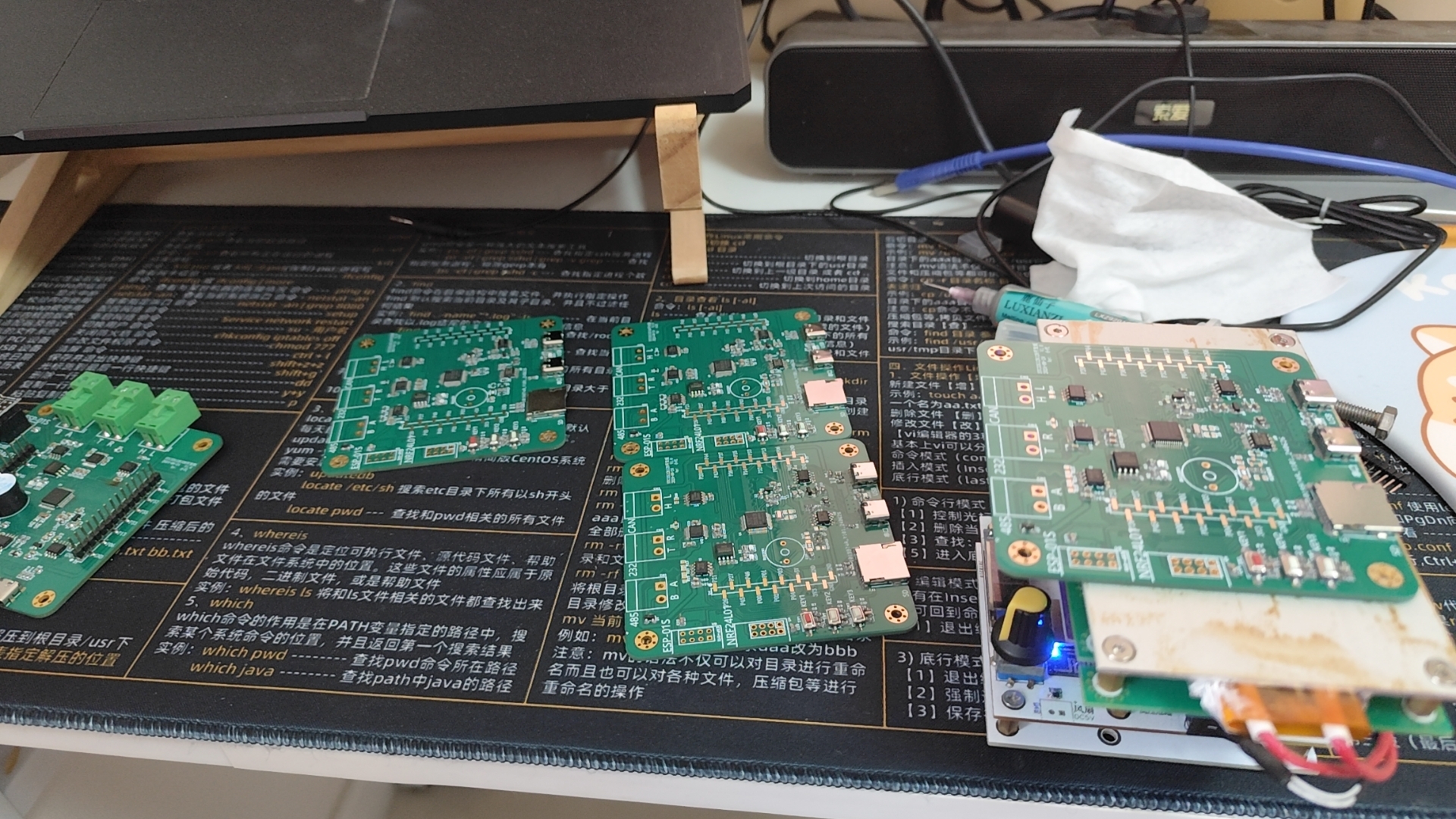
The overall board design features:
1. Three customizable buttons
; 2. Two LEDs
; 3. Dual Type-C ports for program emulation and burning;
4. An active buzzer;
5. An SD card interface for file system expansion;
6. An ESP8266-01S communication interface;
7. NRF24L01;
8. WQ28128;
9. AT2402;
10. A 485 communication interface;
11. A 232 communication interface;
12. A CAN communication interface
; 13. All unused I/O ports pulled out, and a power port.
1~STC32---Multitasking.zip
2~STC32---Add Buzzer.zip
PDF_STC32G12K128 development board.zip
Altium_STC32G12K128 development board.zip
PADS_STC32G12K128 development board.zip
BOM_STC32G12K128 development board.xlsx
93860
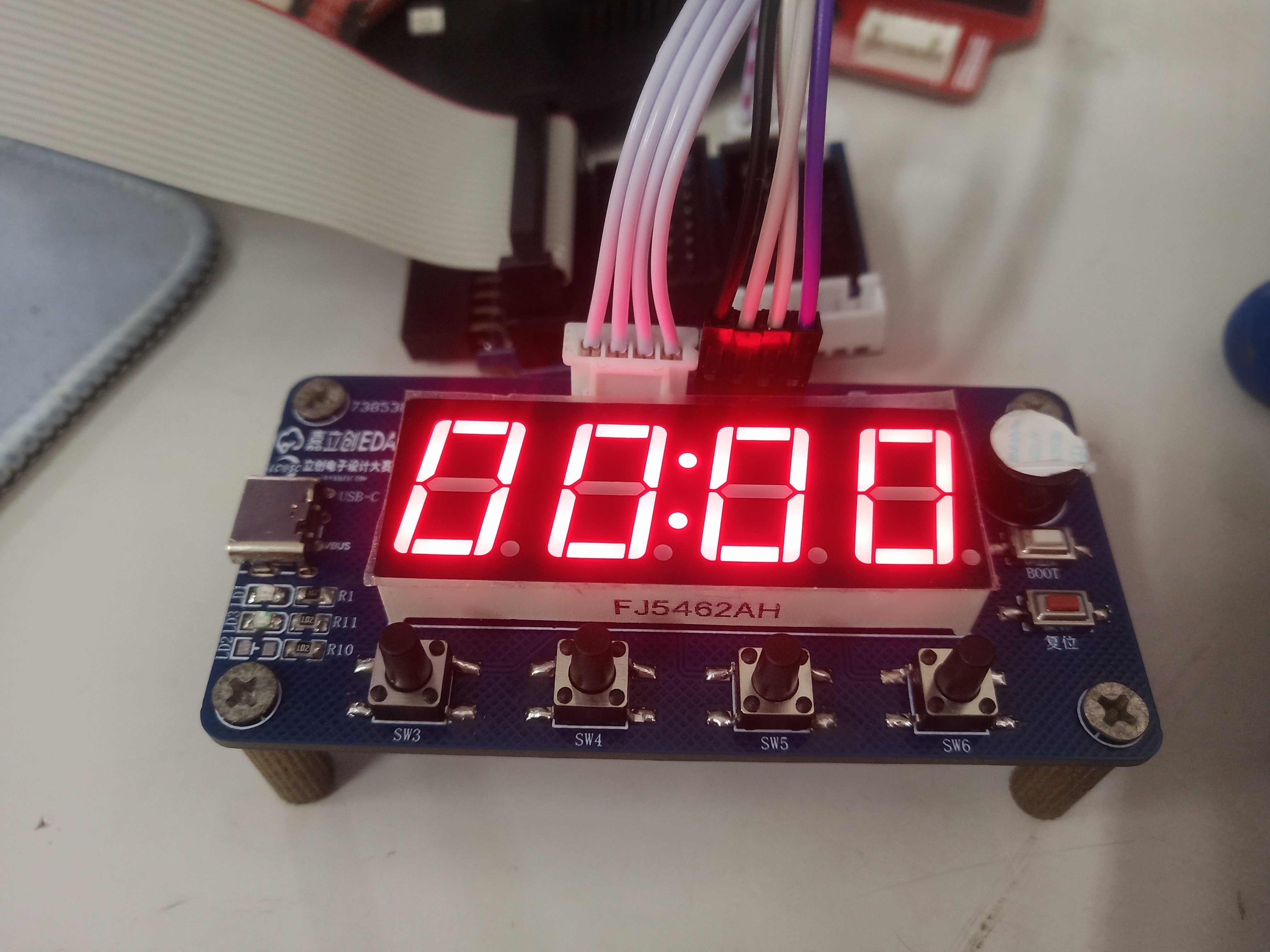
#8th LCSC Electronic Design Contest# Desktop Electronic Clock Design Based on Renesas Microcontroller
This project is a desktop electronic clock design based on the Renesas R7FA2E1A72DFL chip. It uses a four-digit 0.56-inch common cathode digital tube to display time, temperature, etc., and a DHT11 temperature and humidity sensor to collect ambient temperature and humidity.
1. Project Function:
This project is a desktop electronic clock design based on the Renesas R7FA2E1A72DFL chip. It uses a four-digit 0.56-inch common cathode LED display to show time, temperature, etc., and employs a DHT11 temperature and humidity sensor to collect ambient temperature and humidity data.
2. Hardware Resources
: 2.1 Main Control Chip: R7FA2E1A72DFL
The main control microcontroller uses the R7FA2E1A72DFL, with an operating voltage between 1.6V and 5.5V, a maximum clock frequency of 48MHz, and supports up to 128KB of FLASH, 16KB of SRAM, and a 12-bit AD conversion controller. The chip integrates a crystal oscillator, eliminating the need for an external crystal oscillator. It also integrates touch functionality, enabling touch operation without a dedicated touch chip.
2.2 Power
Supply: The power supply circuit mainly consists of a TYPE-C interface and a power indicator light. It uses a 2-pin TYPE-C interface, which is simple, convenient, and easy to solder.
The power switching circuit consists of a P-channel MOSFET, a pull-down resistor, and a diode. When the TYPE-C interface is connected, 5V is supplied, and the gate voltage (G) of the MOSFET is 5V. After passing through a 1N5819 (D3) Schottky diode, the VCC voltage is 4.4V, which is also 4.4V at the source (S). This does not meet the PMOS conduction condition, and the battery power cannot reach the source. When the TYPE-C interface is disconnected, the gate voltage is pulled low. Due to the presence of the body diode, the source voltage will be approximately 3.5V, meeting the PMOS conduction condition. The battery then supplies power to the subsequent circuits. Because of the 1N5819 Schottky diode, the current will not flow back. The battery is charged via a TP5056 lithium battery charging chip. When a TYPE-C interface is connected, the lithium battery is charged simultaneously to ensure sufficient power. LED3 serves as a charging status indicator, and R12 is a charging current feedback resistor. Changing the resistance of R2 changes the overall charging current.
2.3 LEDs:
One power indicator and two charging status indicators.
2.4 Buttons
: One reset button. Pressing and holding the button pulls the reset pin of the main control chip low, and the system enters reset mode. Releasing the reset button returns the reset pin to high level, and the system resumes operation, completing the reset.
One BOOT button. When the BOOT button is not pressed, the BOOT pin is high, and the microcontroller enters Single-chip mode (normal operation mode). When the button is pressed, the BOOT pin is low, and the microcontroller enters SCI-BOOT mode (program download mode).
Four function buttons are used for clock control or other functions.
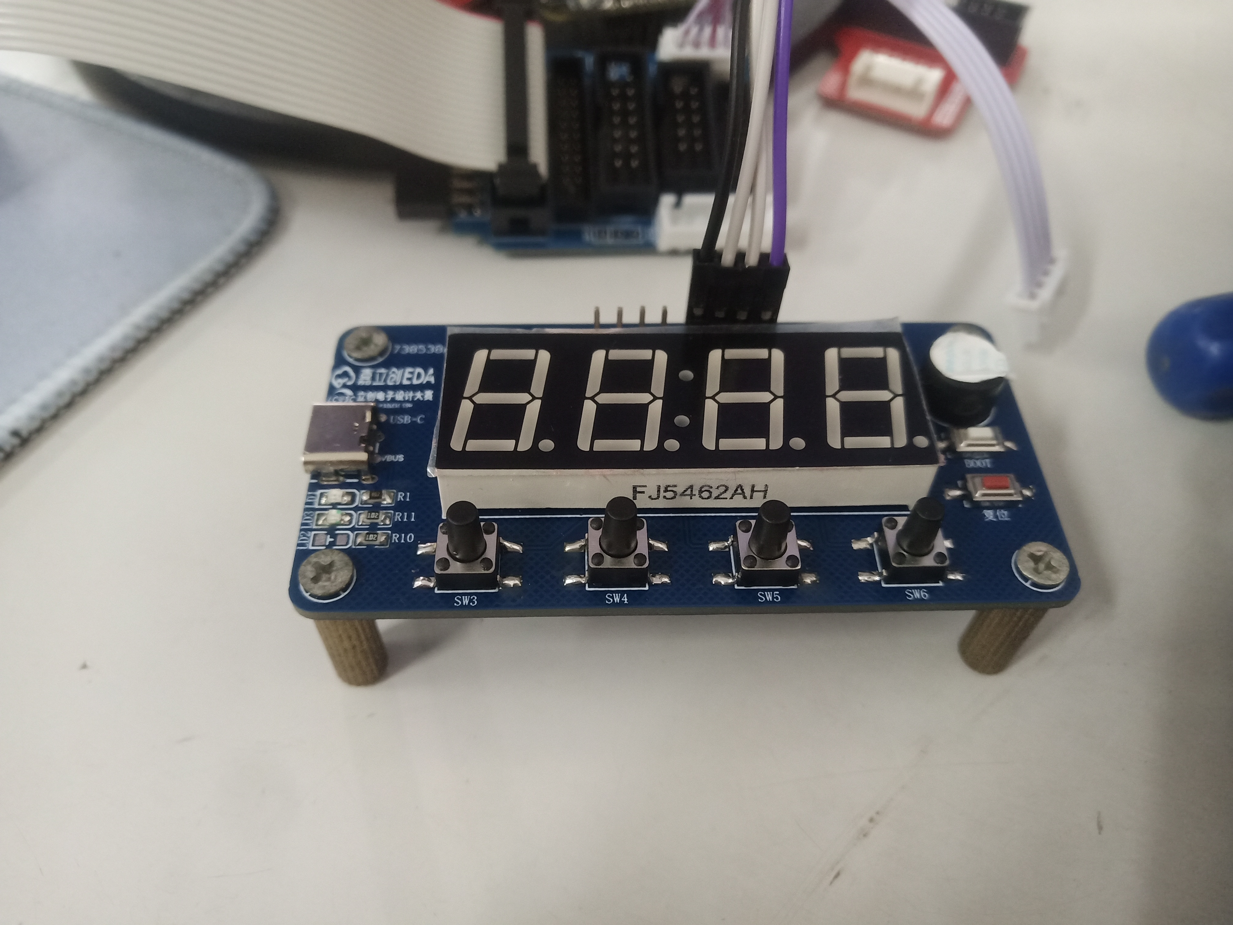
2.5 Peripherals: Digital tube, temperature and humidity sensor, buzzer.
A 0.56-inch common cathode digital tube displays time, temperature, and humidity information;
a DHT11 temperature and humidity sensor detects ambient temperature and humidity. The DHT11 uses a single-bus communication method, requiring an external pull-up resistor. When the bus is idle, its state is high;
a passive buzzer is controlled by an NPN transistor. R5 is a current-limiting resistor, and R6 provides a reliable potential when the chip is powered on or off to prevent interference. The electromagnetic passive buzzer is an inductive load; a diode D2 is added as a freewheeling diode to prevent it from burning out.
2.6 Debugging Interfaces:
The SWD download debugging interface and serial port download debugging interface both use 2.54mm pin headers.
3. Precautions
: 3.1 Drawing:
1. The schematic diagram should be drawn according to the module circuit division, indicating the circuit function.
2. PCB traces should preferably run at right angles; where bends are necessary, use obtuse angles or arcs.
3. Add silkscreen markings and annotations explaining the interface functions.
3.2 Soldering:
1. When soldering, you can click the soldering auxiliary tool in the JLCPCB EDA toolbar for real-time interactive soldering.
2. The soldering sequence should follow the principle of from low to high to avoid affecting the soldering of small components.
3. When soldering the top layer, it is recommended to solder the main control chip first to avoid other components affecting the soldering.
4. When soldering pin headers, a blank board or perforated board can be used to support them to prevent skewed soldering and affect use.
4. Demonstration : 4.1
Physical Demonstration : LCPCB Training Camp - Electronic Clock Design Based on Renesas Microcontroller_Bilibili_bilibili
LCSC Training Camp Electronic Clock.mp4
PDF_#8th LCSC Electronic Design Contest# Desktop Electronic Clock Design Based on Renesas Microcontroller.zip
Altium_#8th LCSC Electronics Design Contest# Desktop Electronic Clock Design Based on Renesas Microcontroller.zip
PADS_#8th LCSC Electronic Design Contest# Desktop Electronic Clock Design Based on Renesas Microcontroller.zip
BOM_#8th LCSC Electronic Design Contest# Desktop Electronic Clock Design Based on Renesas Microcontroller.xlsx
93861
Bluetooth proximity switch - a small electronic project
By automatically connecting or disconnecting the Bluetooth module sensor via mobile phone, scene linkage can be achieved, and the Bluetooth signal covers an area of 180 square meters.
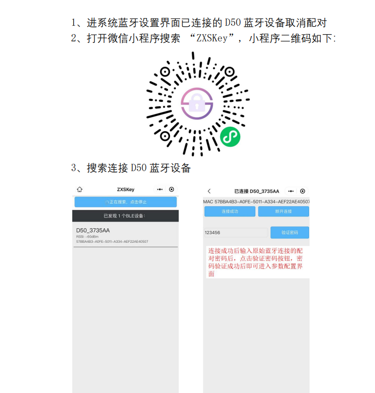
1. The module uses the ZX-D50 Bluetooth module from Shenzhen Zhixing Micro Technology Co., Ltd.

2. The ZX-D50 is a low-power Bluetooth module specifically designed for proximity switch applications by Shenzhen Zhixing Micro Technology Co., Ltd. This module uses the Bluetooth 5.1 protocol and has excellent stability and compatibility. The module supports direct connection to the system's Bluetooth, with automatic reconnection without contact, requiring no app. It supports momentary and constant-on modes, and allows modification of Bluetooth name, pairing password, connection distance, and other parameters via a WeChat mini-program.

3. Component pin diagram

. 4. Mini-program settings.
5. Verification successful.
ProProject_Sensitive Unlock 2024-07-01_16-02-21_2024-07-05.epro
WeChat_20240709103027.mp4
PDF_Electronic Project: Bluetooth Proximity Switch.zip
Altium_Electronic Project: Bluetooth Proximity Switch.zip
PADS_Electronic Project: Bluetooth Proximity Switch.zip
BOM_Electronic Project: Bluetooth Proximity Switch.xlsx
93863
Light Hammer 200 Boost Plate
The booster plate of the Light Hammer 200 flashlight
Introduction and production process of a 1-1.6mm thick
flashlight: The old man upstairs thought it was dawn. 200 RMB hand-made 200W 27000lumen flashlight_Bilibili_Bilibili
Light Hammer 200 Replica Exchange Group: 522608529 You can ask me questions in there if you encounter any problems during the replica process.
Light Hammer 200 Reflector Cup.stl
Light Hammer 200 Reflective Film Mold.stl
Light Hammer 200 Lamp Tube.stl
Light Hammer 200mm lamp head, 3mf
PDF_Light Hammer 200 Boost Voltage Plate.zip
Altium_Light Hammer 200 Boost Power Supply Board.zip
PADS_Light Hammer 200 Boost Voltage Board.zip
BOM_Light Hammer 200 Boost Printer.xlsx
93864
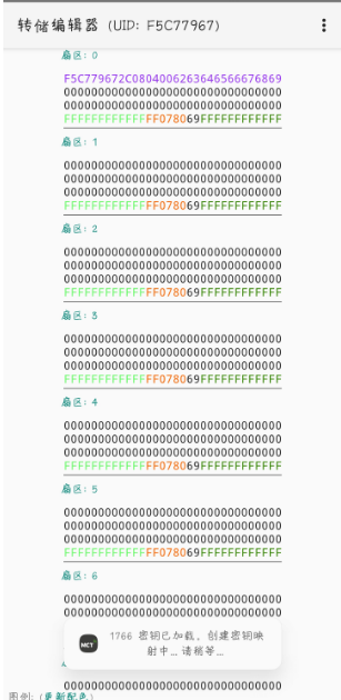
NFC version iron sword
This design follows the original design at https://oshwhub.com/ftp_li/wo-de-shi-jie-tie-jian, scaled down to a 1:1 ratio, and incorporates an NFC coil. It has been successfully verified.
1. Size;
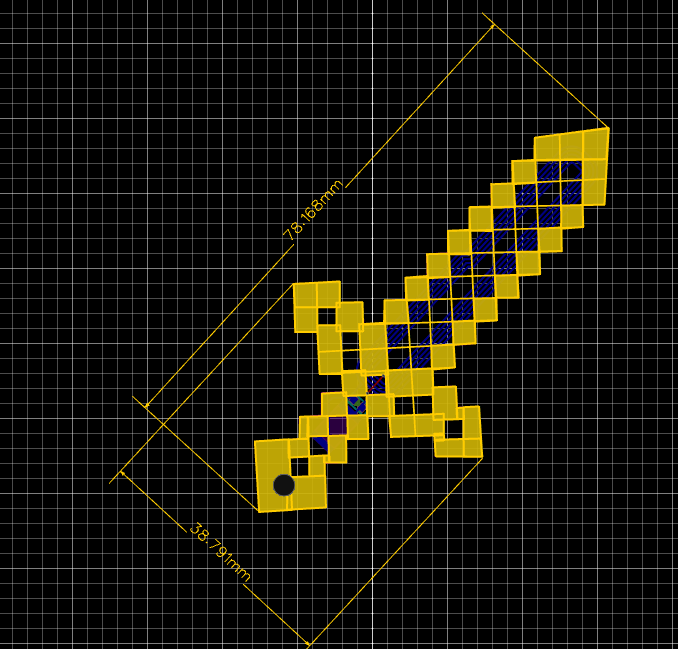
2. Size comparison with AA batteries;

3. Functionality verified successfully.
ProProject_Minecraft PCB Tool Manufacturing Adventure_2024-07-09.epro
PDF_NFC version of the iron sword.zip
Altium_NFC version of the iron sword.zip
PADS_NFC version of the iron sword.zip
BOM_NFC version of the Iron Sword.xlsx
93866
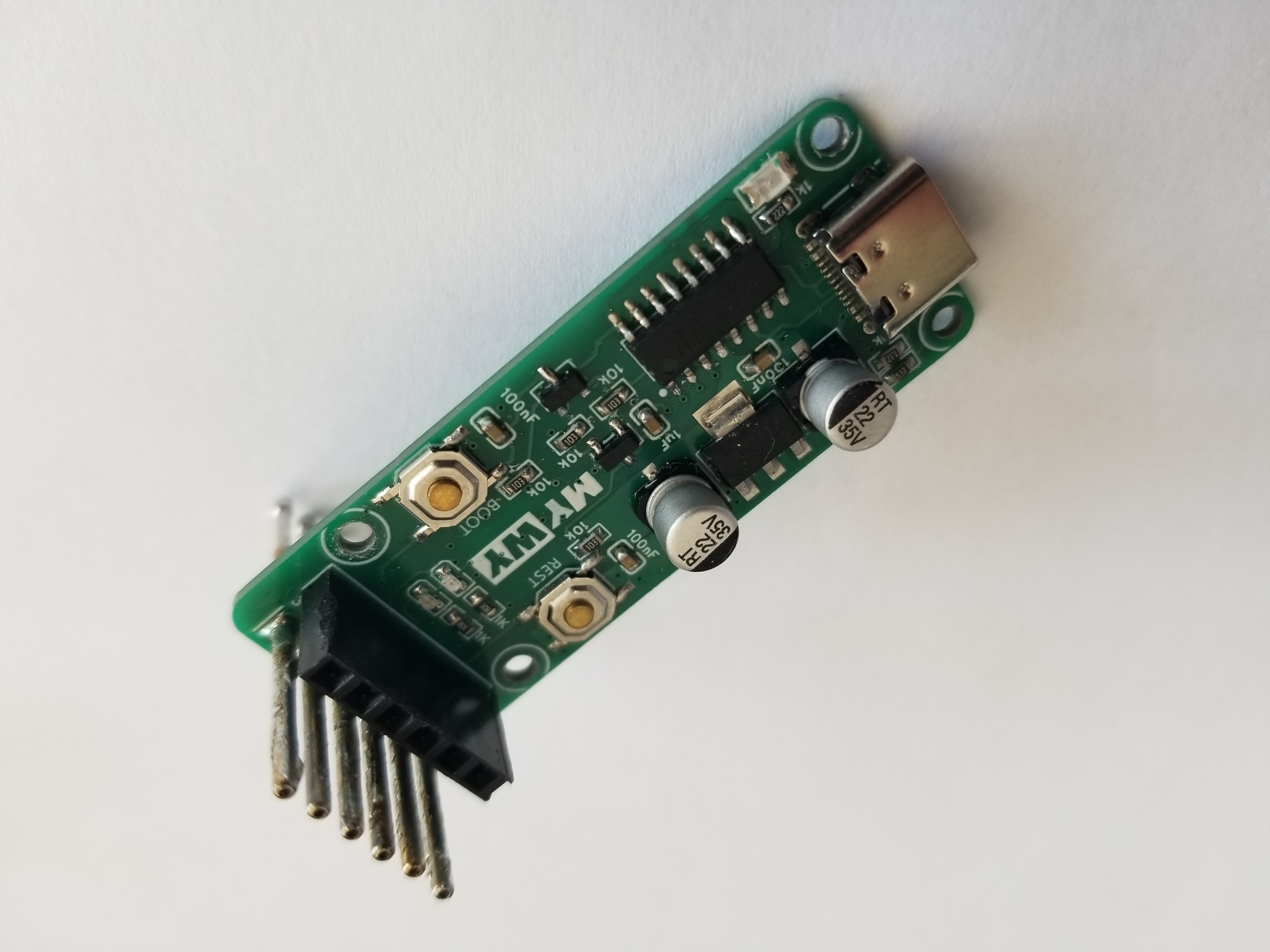
ESP Universal Downloader - Probe (Verified)
The CH340C-based serial port programmer can be used with Espressif ESP series and Holtek AIR series chips for serial port downloading.
This is a serial port programmer based on the CH340C chip, compatible with Espressif ESP and Hexagon AIR series chips.
The circuit design references the ESP Air Burner circuit by Xiaole.Tao on this platform
:
based on the CH340C, simple peripheral circuitry;
automatic downloading circuitry for easy manual operation;
TX and RX indicator lights for clear download status;
2.54mm header pins for general-purpose use;
P100-D2 probes; designed with a programming clip for easy onboard programming.
The design has been verified; 3D printing files are attached.
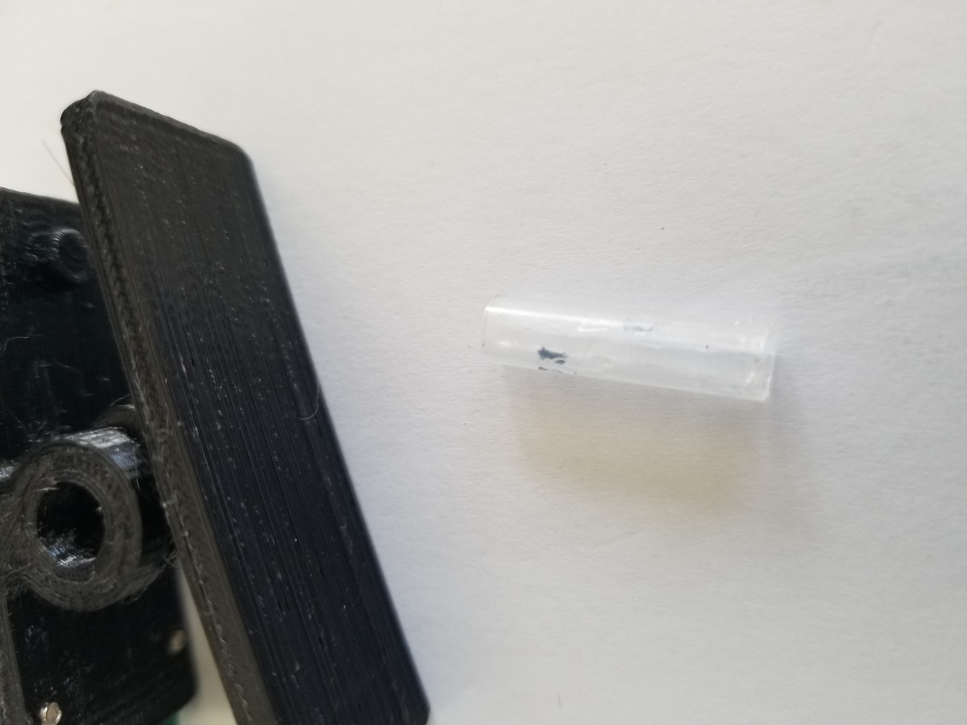
A section of the clip's shaft was simply cut from a water-based pen refill.

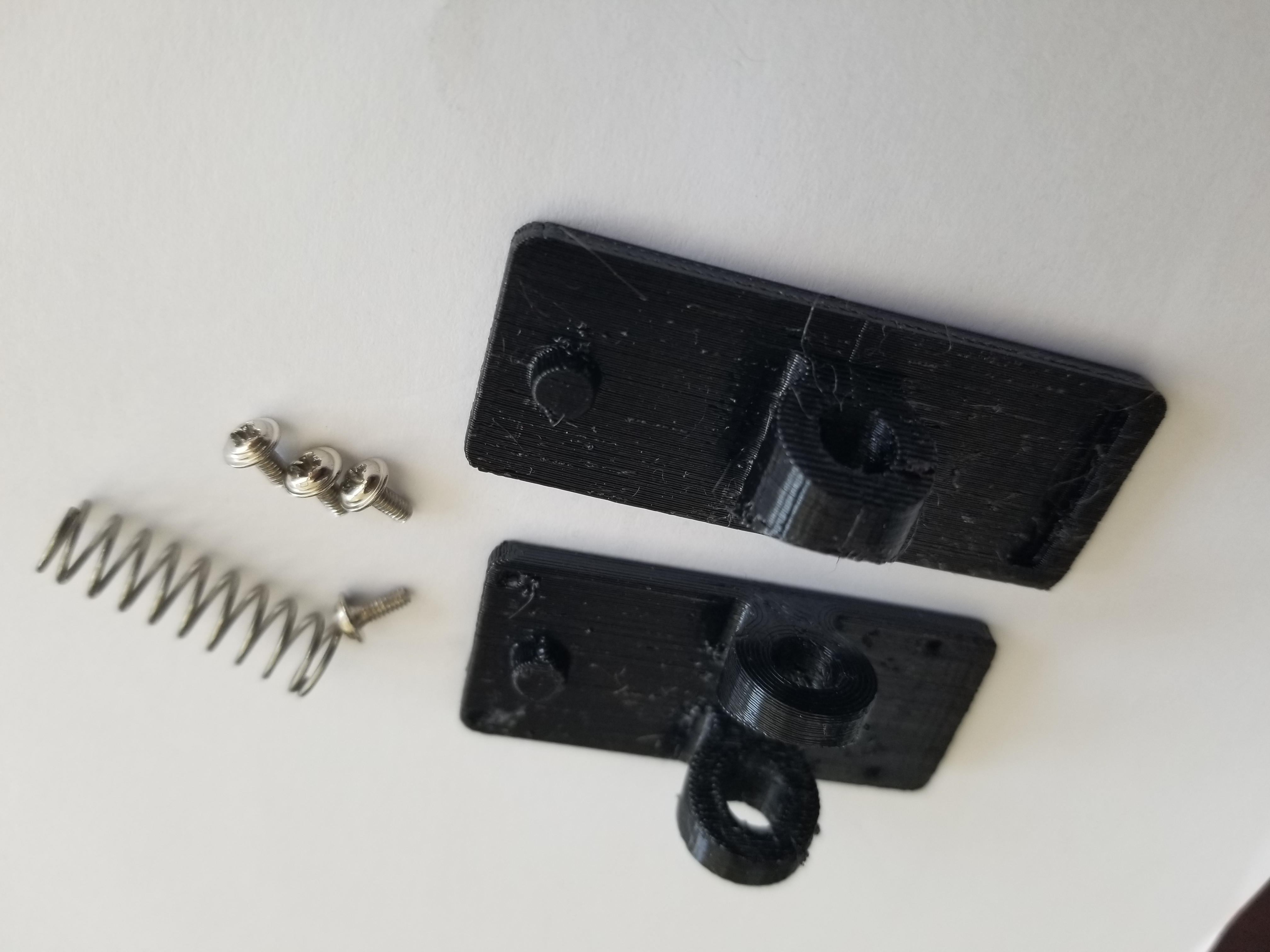
part1.STL
part2.STL
PDF_ESP Universal Downloader_Probe (Verified).zip
Altium_ESP Universal Downloader_Probe (Verified).zip
PADS_ESP Universal Downloader_Probe (Verified).zip
BOM_ESP Universal Downloader_Probe (Verified).xlsx
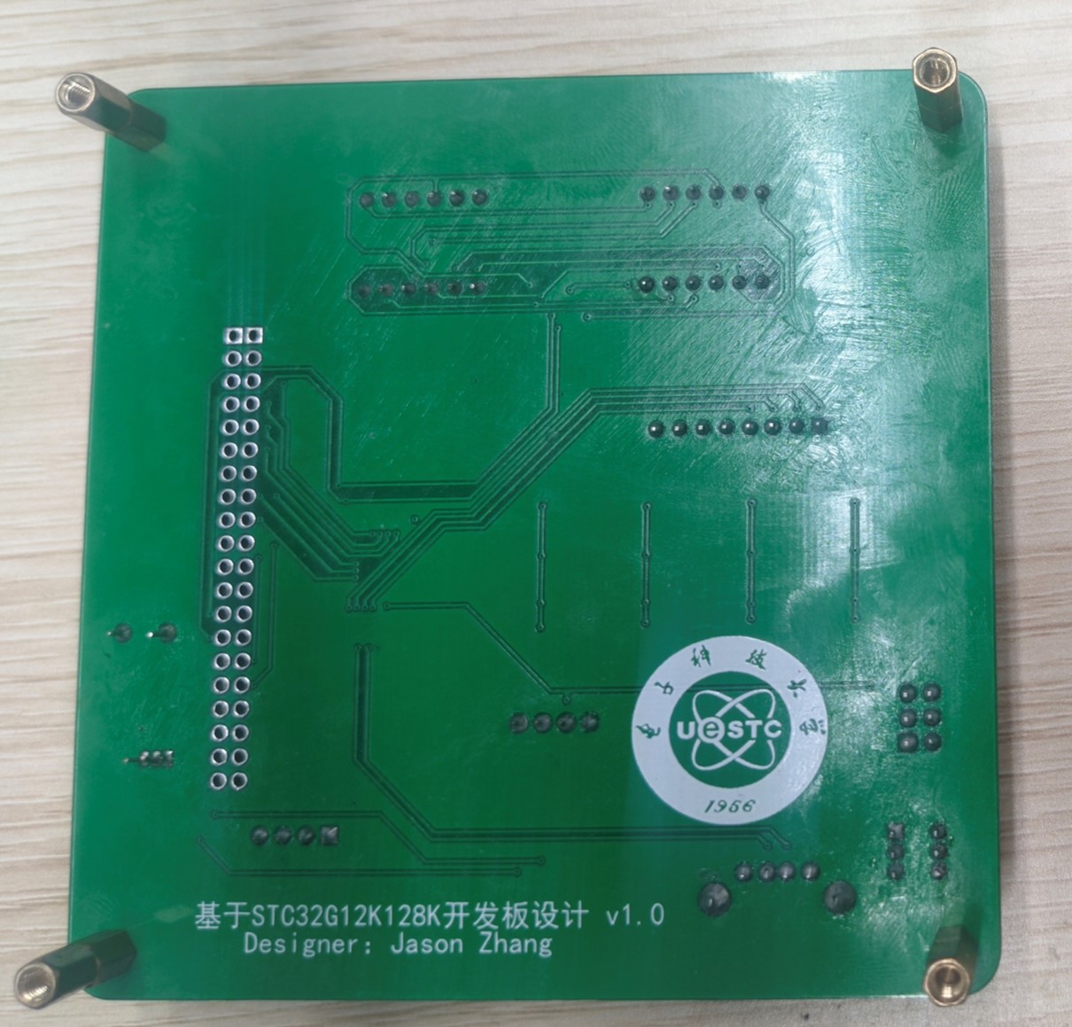
93867
Design based on STC32G12K128K development board
This development board design is based on the STC32G12K128K microcontroller and integrates a digital tube, matrix keyboard, OLED, buzzer, and DS18B20 temperature sensor.
This development board design, based on the STC32G12K128K microcontroller, integrates a digital tube display, a matrix keyboard, an OLED screen, a buzzer, and a DS18B20 temperature sensor.
The 8-digit common-cathode digital tube is driven by two 74HC573 chips.
The matrix keyboard has 16 keys and is driven by 7 I/O pins.
The 0.96-inch OLED uses the II2C protocol , and
the DS18B20 uses a single-bus protocol
. The buzzer is an active buzzer driven by an SS8850 transistor
. Power is supplied via a USB direct connection and includes a self-locking switch for easy switching.
An AMS1117 step-down chip is added to convert +5V to 3V3V for future power supply of other devices.
A Bluetooth module interface is also provided for future wireless data transmission.

Digital tube test.mp4
OLED+DS18B20+Matrix Keyboard.mp4
Demo_code.rar
PDF_Design Based on STC32G12K128K Development Board.zip
Altium_Design based on STC32G12K128K development board.zip
PADS_Design Based on STC32G12K128K Development Board.zip
BOM_Design Based on STC32G12K128K Development Board.xlsx
93868
STC32G12K128 Minimum Board
STC32G12K128 Minimum Board
The basic functions of the minimum board have been verified and it can be programmed using hardware USB. It includes a 5V reference voltage chip for the ADC, an external EEROM, an additional 3.3V power supply, and multiple buttons and LEDs. All pins, as well as VCC and GND, are exposed, requiring few components while offering rich functionality.
![]()
PDF_STC32G12K128 Minimum Board.zip
Altium_STC32G12K128 Minimum Board.zip
PADS_STC32G12K128 Minimum Board.zip
BOM_STC32G12K128 Minimum Board.xlsx
93869
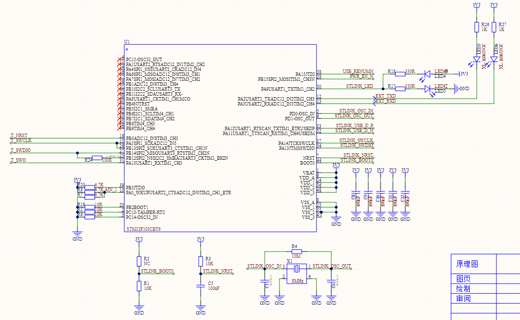
STLINK-V2.1 (Verified)
ST-Link version V2.1 adds some protection components and supports the original STM32F103CBT6/Hezhou Air32F103CBT6.
I. Inspiration Sources
1. https://oshwhub.com/CYIIOT/ST_LINK-V2_1
2. NUCLEO-F767ZI onboard STLink-V2.1
II. Project Introduction
The first version of this project used a four-layer board. The second version of this project uses a two-layer board, which is convenient for cost reduction and efficiency improvement during mass production, and also helps with 996/007 work schedules and layoffs.
III. USB Interface and Re-enumeration Circuit
This project uses a Type-C interface, with a package compatible with the cheap Type-C female connectors from Uxin and the 5A Type-C female connectors from Hande. For other brands and models of female connectors, please verify them yourself. This design adds 5.1K pull-down resistors to CC1 and CC2. You can use a dual-C port data cable for debugging/power supply. An SMAJ6.8CA is added to the 5V power supply of the Type-C input for protection. Hopefully, it can protect your computer if the development board burns out. Of course, this is just a hope.
This design features a USB re-enumeration circuit, which automatically re-enumerates devices after upgrading the STLink firmware, eliminating the need for repeated USB cable plugging and unplugging and protecting the USB interface from your fingernails.
The USB data cable in this design incorporates a USBLC6-2SC6 ESD protection device. Pins 1/6 and 3/4 of the USBLC6-2SC6 are internally connected. You can either extend the circuitry on the PCB (as ST does), or force the signal through the ESD protection device (as this design does).

IV. LDO:
This design uses an RT9013-33 LDO, which you can replace with other LDOs.

V. MCU
: This design has been verified to support the original STM32F103CBT6 and the Heze Air32F103CBT6.
Note that although the Air32F103CBT6 and Air32F103CCT6 are priced the same, please do not purchase the Air32F103CCT6. When using the CCT6, the STLinkV2.J28.M18 firmware can be downloaded to the STLink board normally, and related functions work correctly. However, after upgrading the STLink board firmware using the upgrade software, a USB connection failure occurs.
This problem does not occur when using the original STM32F103CBT6 or Air32F103CBT6, initially suspected to be due to the Flash page size being 2K.

VI. Output Electronic Switch
: This design includes an output electronic switch. The external 3V3 is controlled by ST-Link to turn on/off. Note that this electronic switch does not have short-circuit protection; it is simply an electronic switch. It is recommended that you remove this component.
VII. Program Flowchart
: Include the program flowchart and upload the source code in the attachment.
VIII. External Interfaces and ESD Protection Devices
This design introduces the following interfaces:
1. STLINK's own SWD download interface. You need an STLink device to download the firmware to this downloader. If you don't have an STLink device, you can consider replicating the STLink device used in this design. However, you still need an STLink device to download the firmware to this downloader. If you don't have an STLink device, you can...
2. UART serial port
3. SWD and RST interfaces

IX. Precautions
Do not use AIR32F103CCT6. Do not use AIR32F103CCT6. Do not use AIR32F103CCT6. The original 32-bit is already cheap enough; it is recommended to use the original STM32F103CBT6.
PDF_STLINK-V2.1(verified).zip
Altium_STLINK-V2.1(verified).zip
PADS_STLINK-V2.1(verified).zip
BOM_STLINK-V2.1(verified).xlsx
93870
electronic


 京公网安备 11010802033920号

 EM6325BY-2.9


