GitHub - LovelyA72/GB-Flash-Cart-32K: Easy to build open source 32KB Gameboy Flash cart Flashcart KiCAD Schematic and PCB File
https://www.bilibili.com/video/BV1GS411A7Wc/?spm_id_from=333.999.0.0&vd_source=e3522c24494f1912b21e6ce2c7f03ae2
Introduction and production process of a 1.0mm thick
flashlight: The old man upstairs thought it was dawn. 200 yuan handmade 200 watt 27000 lumen flashlight_Bilibili_bilibili
Battery pack making tutorial: [Open source] 200 watt 30000 lumen flashlight light hammer 200 replica tutorial 1: Battery pack_Bilibili_bilibili
Light hammer 200 replica exchange group: 522608529 You can ask me questions in there if you encounter problems during the replica process.

eve25p_final.srec
Battery spot welding mold.stl
PDF_Light Hammer 200 Battery Protection Board.zip
Altium_Light Hammer 200 Battery Protection Board.zip
PADS_Light Hammer 200 Battery Protection Board.zip
BOM_Light Hammer 200 Battery Protection Board.xlsx
93896
EastMartrix Pixel Clock Master
Modified based on the open-source code of Da Congming on Bilibili.
The surface-mount resistor was changed to a 0603 package, and the photoresistor was directly soldered onto the PCB.
This controls the EastMartrix pixel screen display.
PDF_EastMartrix Pixel Clock Master Controller.zip
Altium_EastMartrix Pixel Clock Master Controller.zip
PADS_EastMartrix Pixel Clock Master Controller.zip
BOM_EastMartrix Pixel Clock Master Controller.xlsx
93897
Industrial control board PLC_V1.1
A PLC industrial control board, compatible with Mitsubishi FX2N, which can use ladder diagrams written by Mitsubishi.
The main controller is an STM32F103VET6, which has been verified to work properly after flashing custom firmware. It needs to be programmed using a flashing socket. The wiring is only connected and hasn't been optimized yet; I'll optimize it later when I have time.
PDF_Industrial Control Board PLC_V1.1.zip
Altium_Industrial Control Board PLC_V1.1.zip
PADS_Industrial Control Board PLC_V1.1.zip
BOM_Industrial Control Board PLC_V1.1.xlsx
93898
15-24V input, ±35V output power supply based on TPS40210
The SEPIC+CUK circuit based on TPS40210 can realize the step-up and step-down of positive and negative voltages and can be used as the positive and negative power supply for power amplifiers.
Circuit principles, design considerations, and software tools are explained in reference to Professor Tang's related videos: Op-amp Dual Power Supply, Open Source XL6007 SEPIC+CUK Schematic and PCB.
Test results and modification suggestions are provided directly here.
The TPS40210 is an asynchronous boost controller; appropriate switching transistors can be selected to increase output power.
The switching frequency is set to 550kHz, achieving ±35V output.
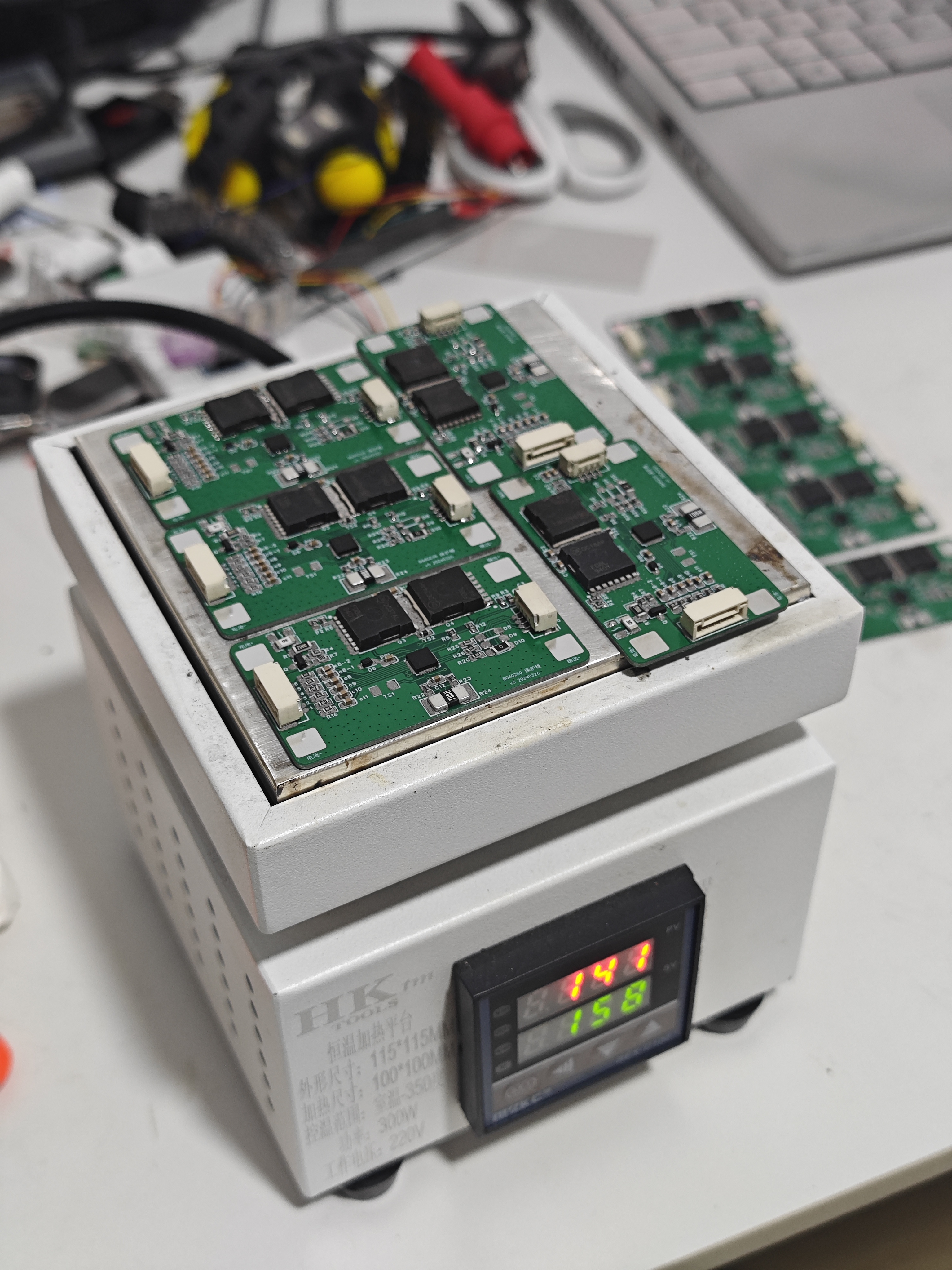
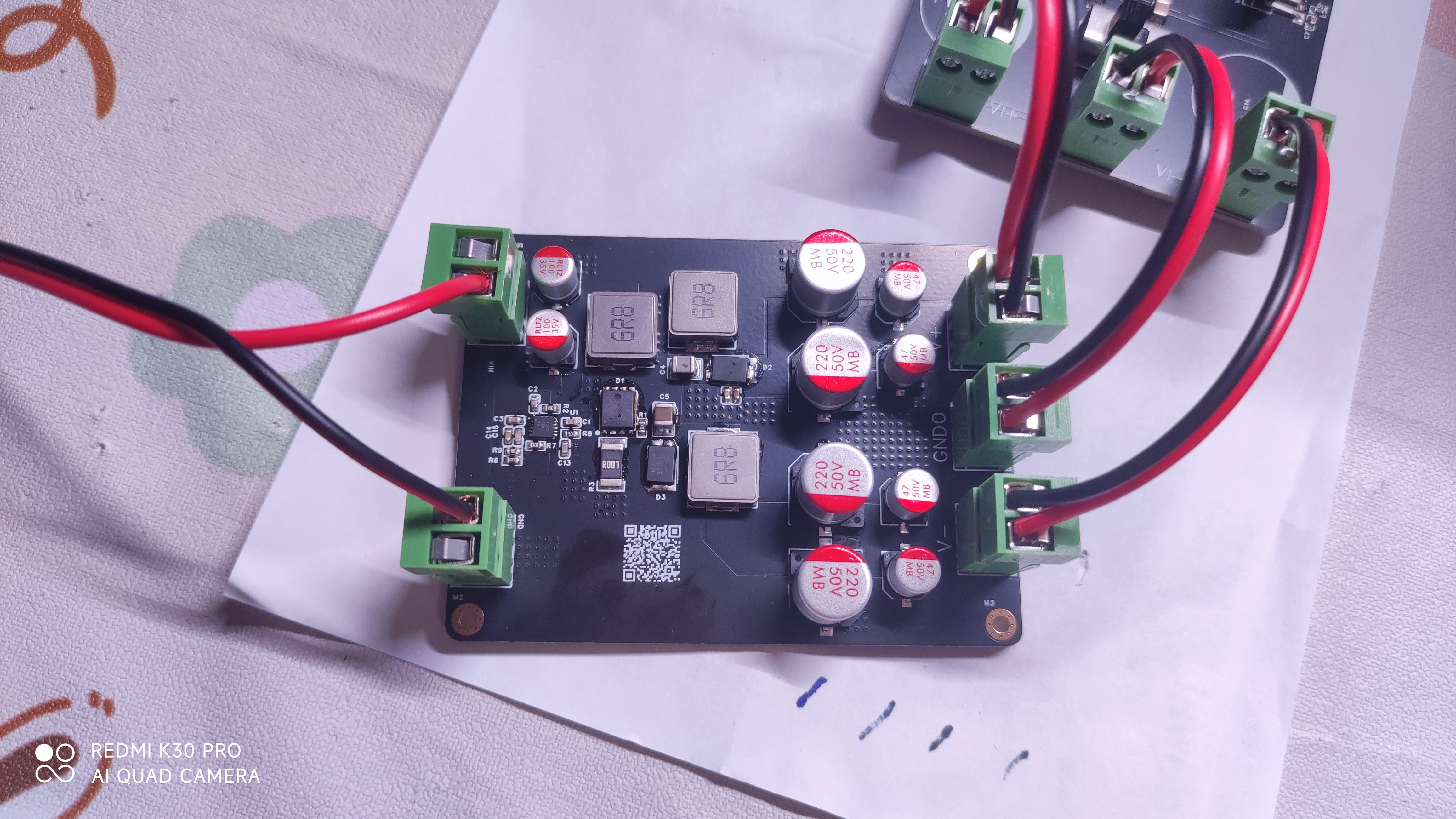
The physical diagram is shown below.
The testing method is as follows:
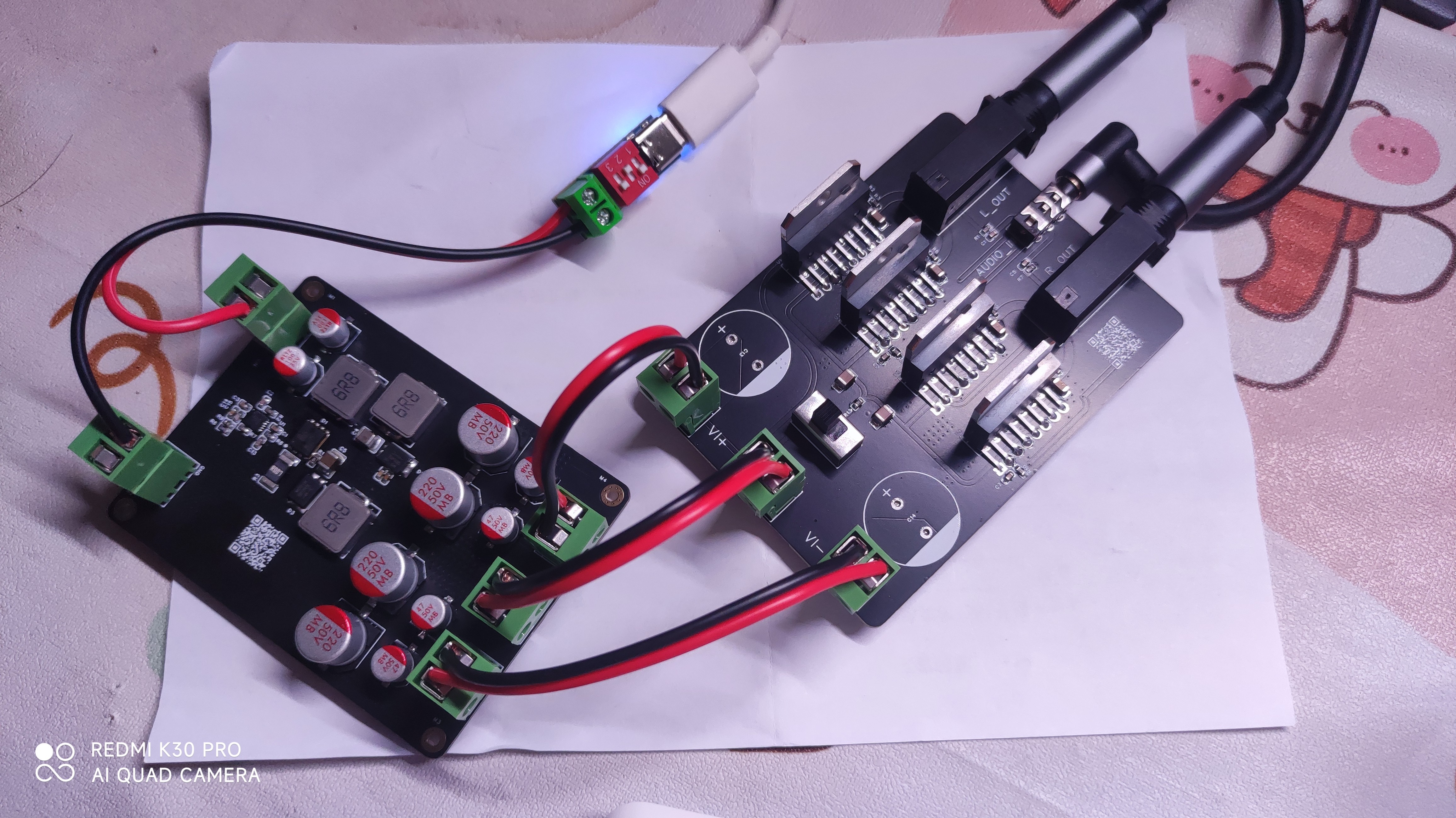
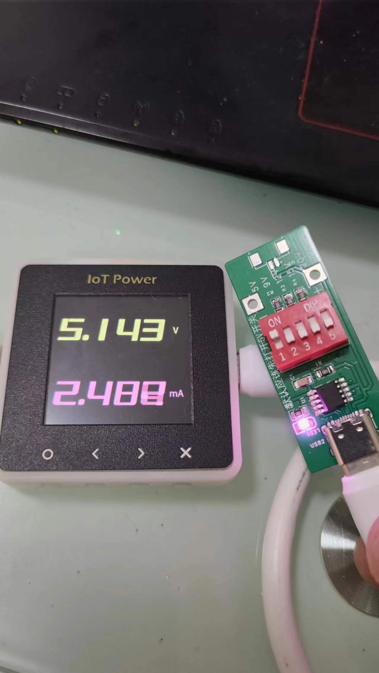
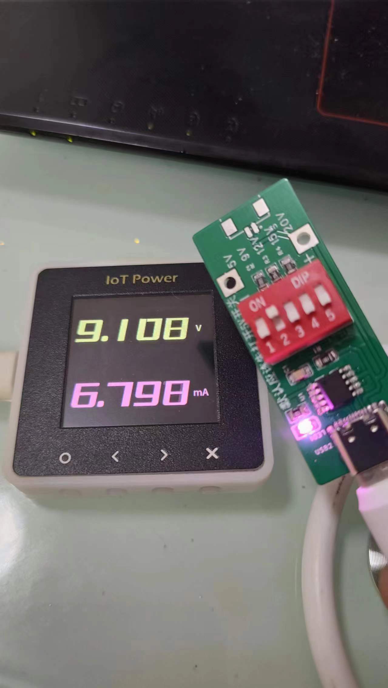
15V and 20V voltages were taken from the power adapter using a CH224K for testing.
The load is a BTL power amplifier circuit built with a TDA7294V.
The filter capacitor on the power amplifier board was not soldered because soldering it would cause abnormal power output. The reason is estimated to be that the output capacitor is too large, resulting in excessive current during power-on and triggering the chip's protection function (the load current is designed for 2A).
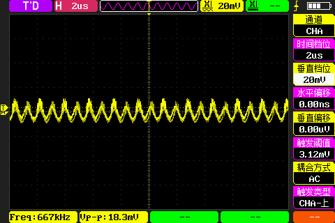
The actual output power is unclear. There was no resistor as a load, and the output volume was not turned up too high to avoid disturbing neighbors. Ripple was measured at the following four locations.

Significant differences were encountered during positive voltage measurements.
The result measured on the power board was unusual, reaching 72mV.

On the amplifier board, the ripple measured from the large capacitor pad was only around 18mV.
The negative voltage was more normal:
approximately 13mV on the power board and

approximately 20mV on the amplifier board.

Furthermore, the inductor temperature was high during operation; a larger package could be considered.
When modifying the wiring layout, care should be taken to minimize the area of the two high-frequency current loops.


PDF_Power Supply Based on TPS40210: 15-24V Input, ±35V Output.zip
Altium_TPS40210-based 15-24V input, ±35V output power supply.zip
PADS_TPS40210-based 15-24V input, ±35V output power supply.zip
BOM_Power Supply Based on TPS40210 15-24V Input, ±35V Output.xlsx
93900
TA7642 AM Receiver
Simple TA7642 AM radio powered by 1.5V
Simple TA7642 AM radio powered by 1.5V
PDF_TA7642 AM Receiver.zip
Altium_TA7642 AM Receiver.zip
PADS_TA7642 AM Receiver.zip
BOM_TA7642 AM Receiver.xlsx
93903
electronic
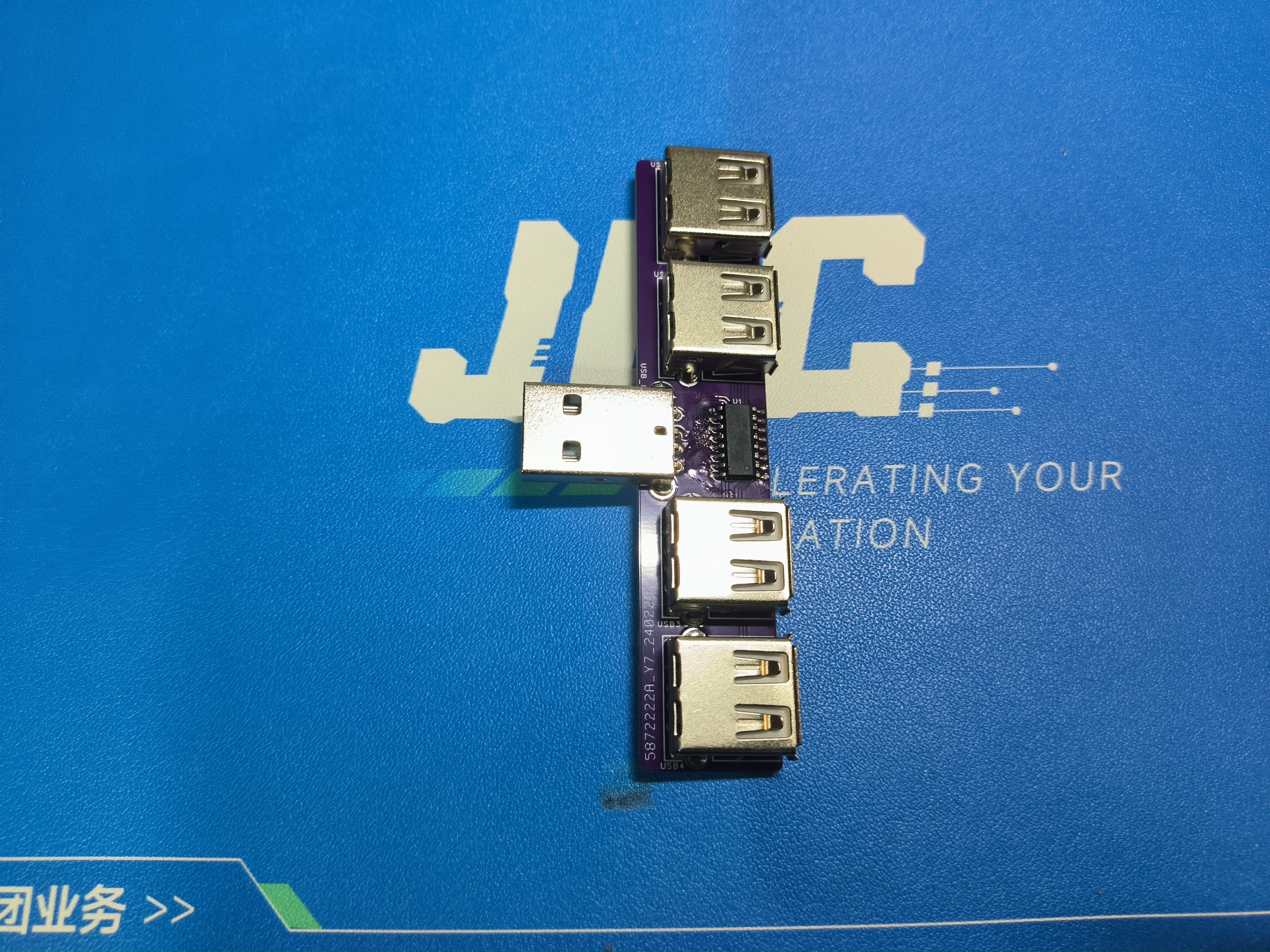 Back:
Back: 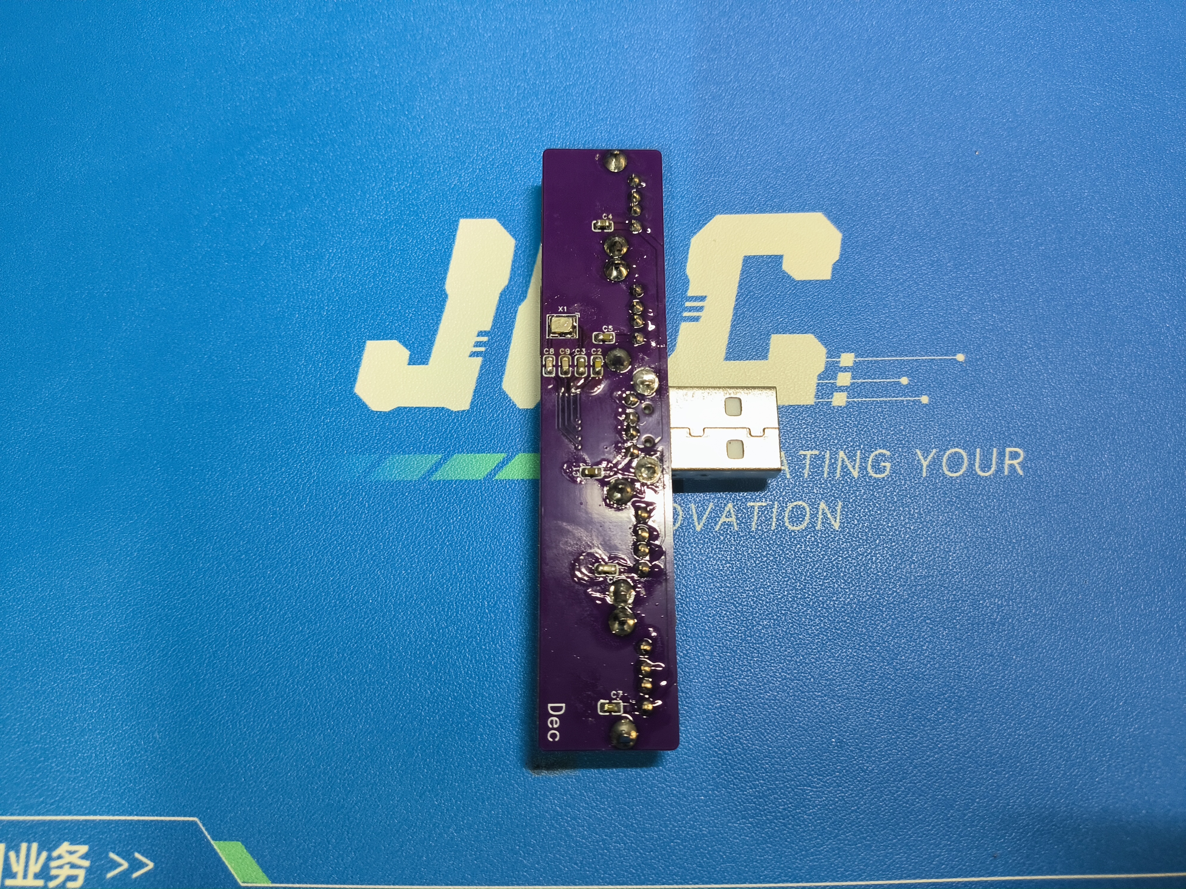 Actual Performance Test:
 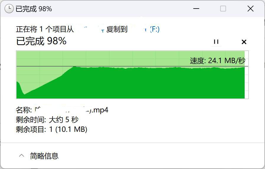 . It can be seen that except for a slow initial period, the transfer speed remained around 24MB/s.
 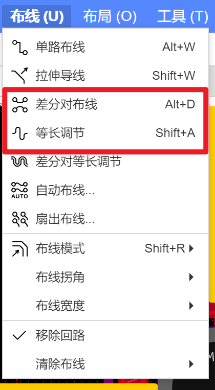 The green box shows the use of this function.
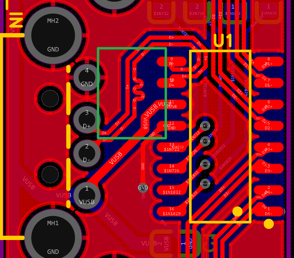


 京公网安备 11010802033920号

 DWM-13-56-S-S-500


