The hardware specifications are detailed in the engineering schematics.
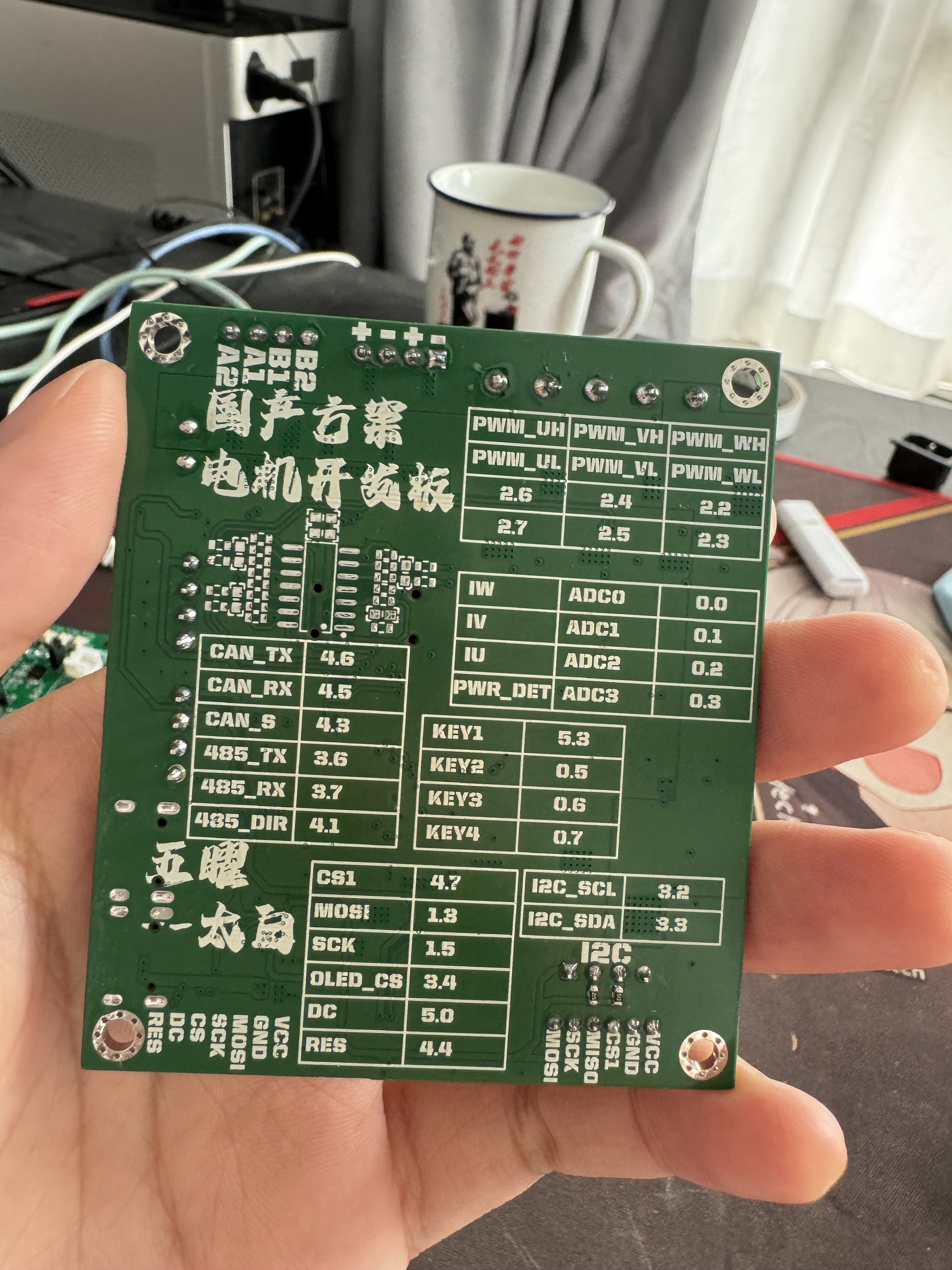
The STC basic development board includes a bus voltage acquisition unit, a two-phase stepper motor driver unit, and a two-channel H-bridge unit. It is mainly used in conjunction with a magnetic encoder for closed-loop control of stepper motors. It also includes a DC brushless motor driver unit with three-phase current detection, which can be used in conjunction with a magnetic encoder for forcible control.
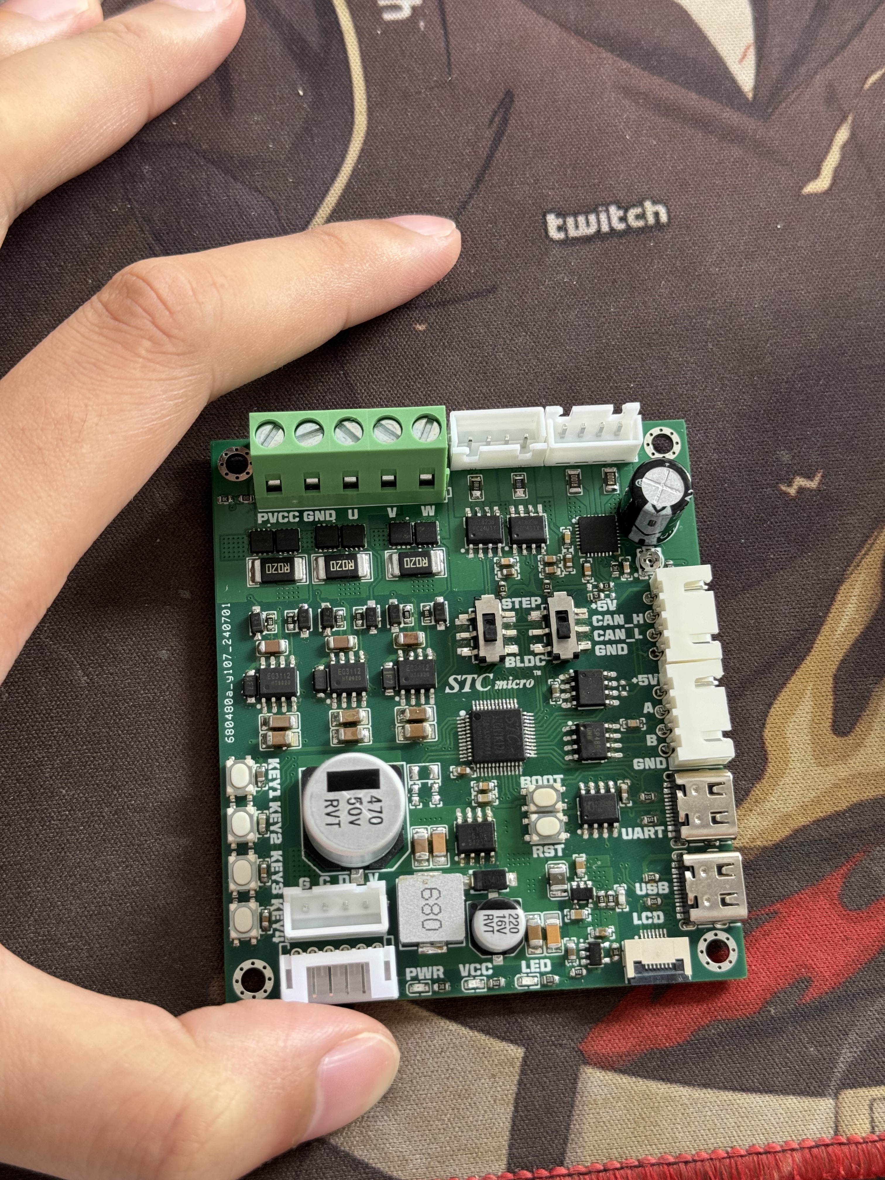
Li Bai spoke to me, opening the gates of heaven for me. The goal is to learn different methods of driving motors by building a small and exquisite development board. Functions include:
bus voltage acquisition x1, two-phase stepper motor driver (GC6609) x1, two-channel H-bridge x1 (mainly for closed-loop control with magnetic encoder), DC brushless motor driver x1 (with three-phase current detection, can be used with magnetic encoder for FOC control), Type-C-USB to UART x1,
CAN bus communication interface x1, RS485 communication interface x1,
I2C interface x1,
SPI interface x1
, user buttons x4, soft reset button x1, boot button x1, bus power indicator x1, microcontroller power indicator x1, user LED x1,
SPI_OLED x1.
Some example programs and AIO programs will be uploaded later.
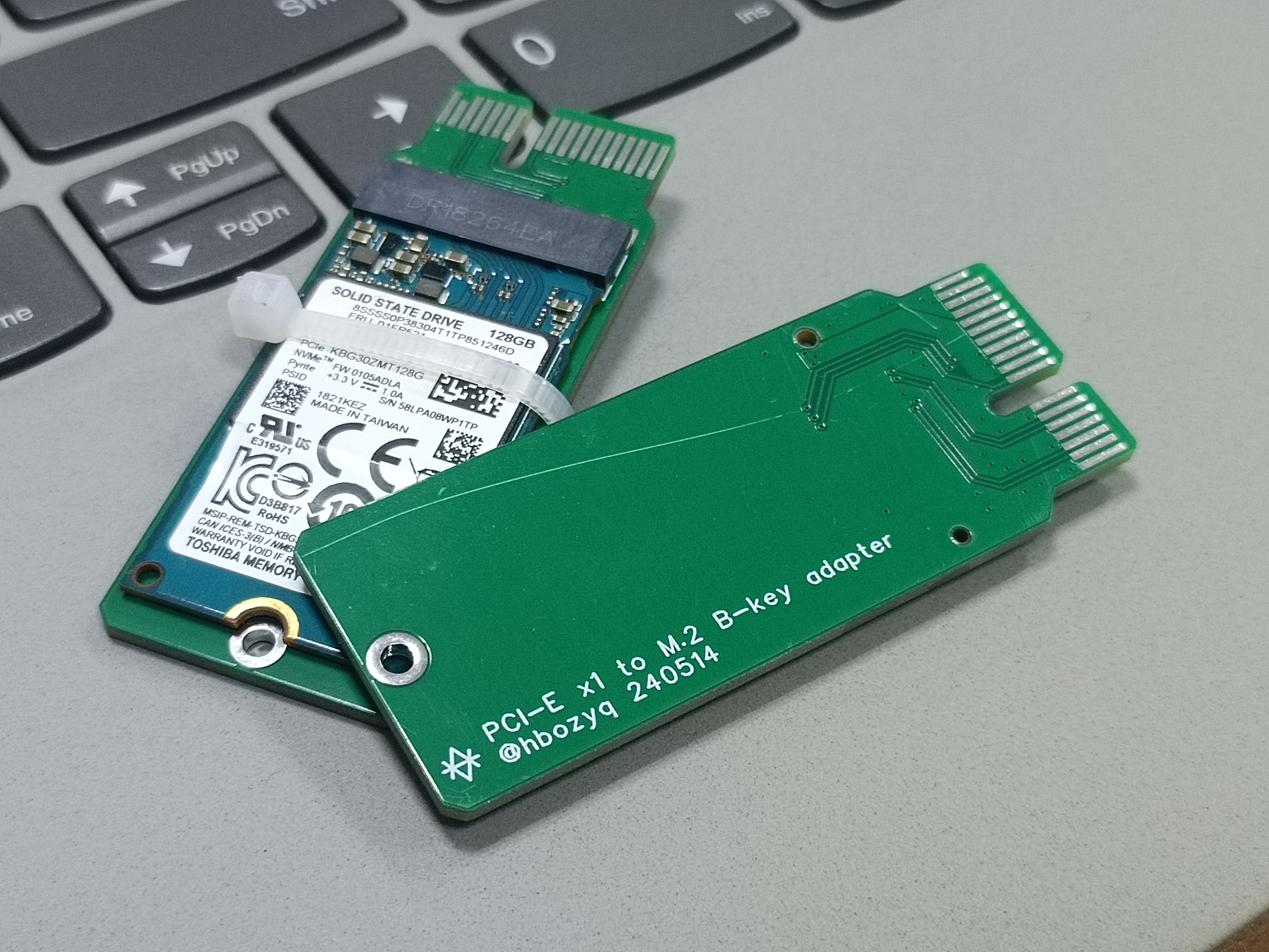
This adapter board is specifically designed for 2242 form factor SSDs. It's small and protrudes slightly, and in actual testing, it fully utilized 3.0x1.
The connector is an M.2 key B, suitable for NVMe protocol SSDs with key B+M (two notches). It cannot be used with SATA protocol SSDs.

PDF_PCIEx1 to M.2 NVME KeyB 2242 specification.zip
Altium_PCIEx1 to M.2 NVME KeyB 2242 specification.zip
PADS_PCIEx1 to M.2 NVME KeyB 2242 specification.zip
BOM_PCIEx1 to M.2 NVME KeyB 2242 specification.xlsx
93942
STC Development Board Xinqi Merchant
A newbie getting started with the STC core board, learning from the experts how to design the board, prototype, solder, install, and program...
haha...
This is a beginner's guide to using the STC core board, primarily for learning. Following experienced users, I learned to use JLCPCB's EAD professional version for PCB design, free immersive prototyping, manual soldering of 0402 components, installing the software from the beginner's tutorial, and performing simple program burning and verification… I successfully completed the entire process and will use the core board for various subsequent learning projects. I've benefited greatly, and I'm grateful for the guidance from the experienced users and for the learning opportunity provided by STC. Haha…
20240704.mp4
PDF_STC Development Board Xinqishang.zip
Altium_STC development board Xinqishang.zip
PADS_STC Development Board Xinqishang.zip
BOM_STC Development Board Xinqi Merchant.xlsx
93943
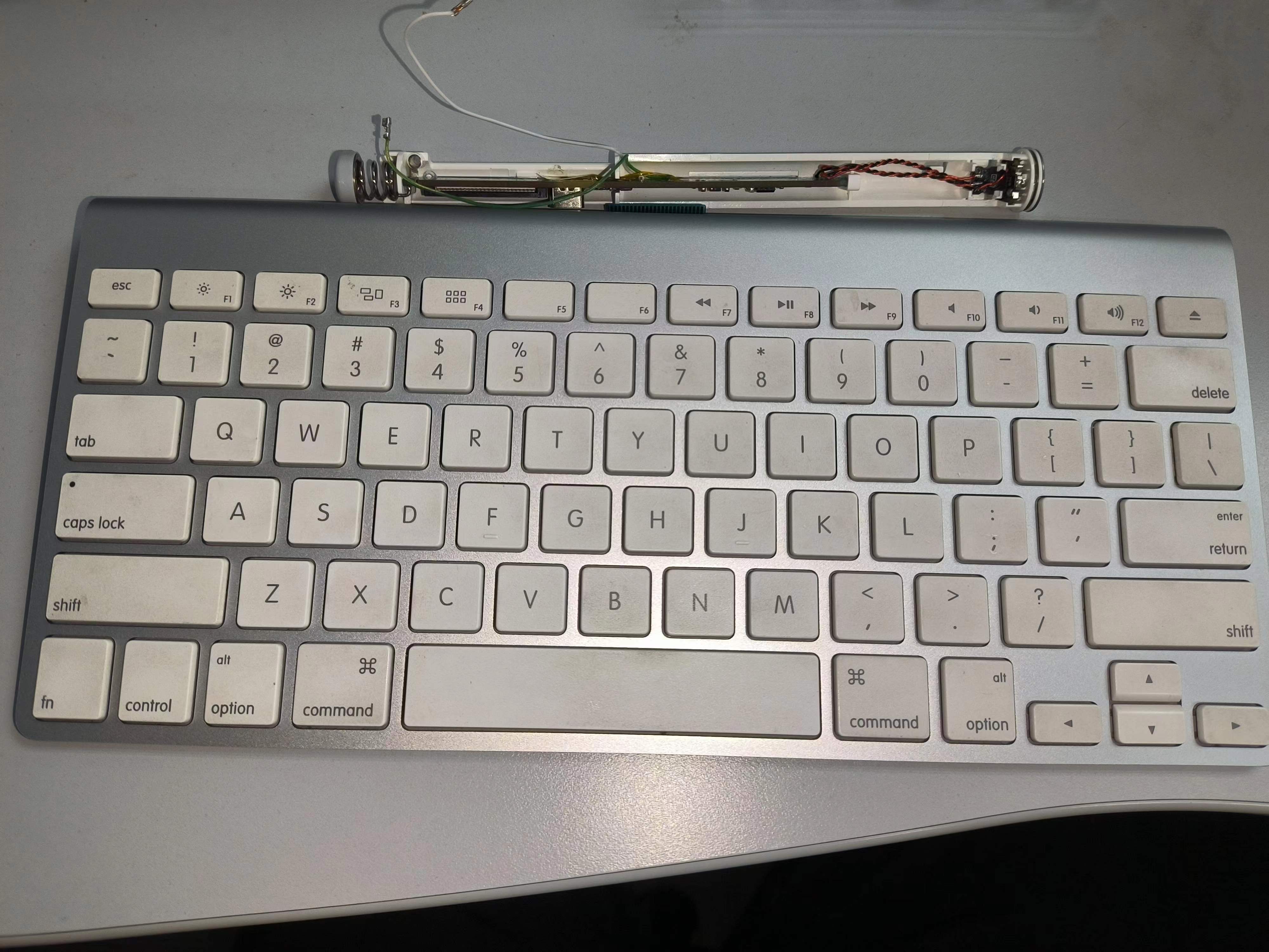
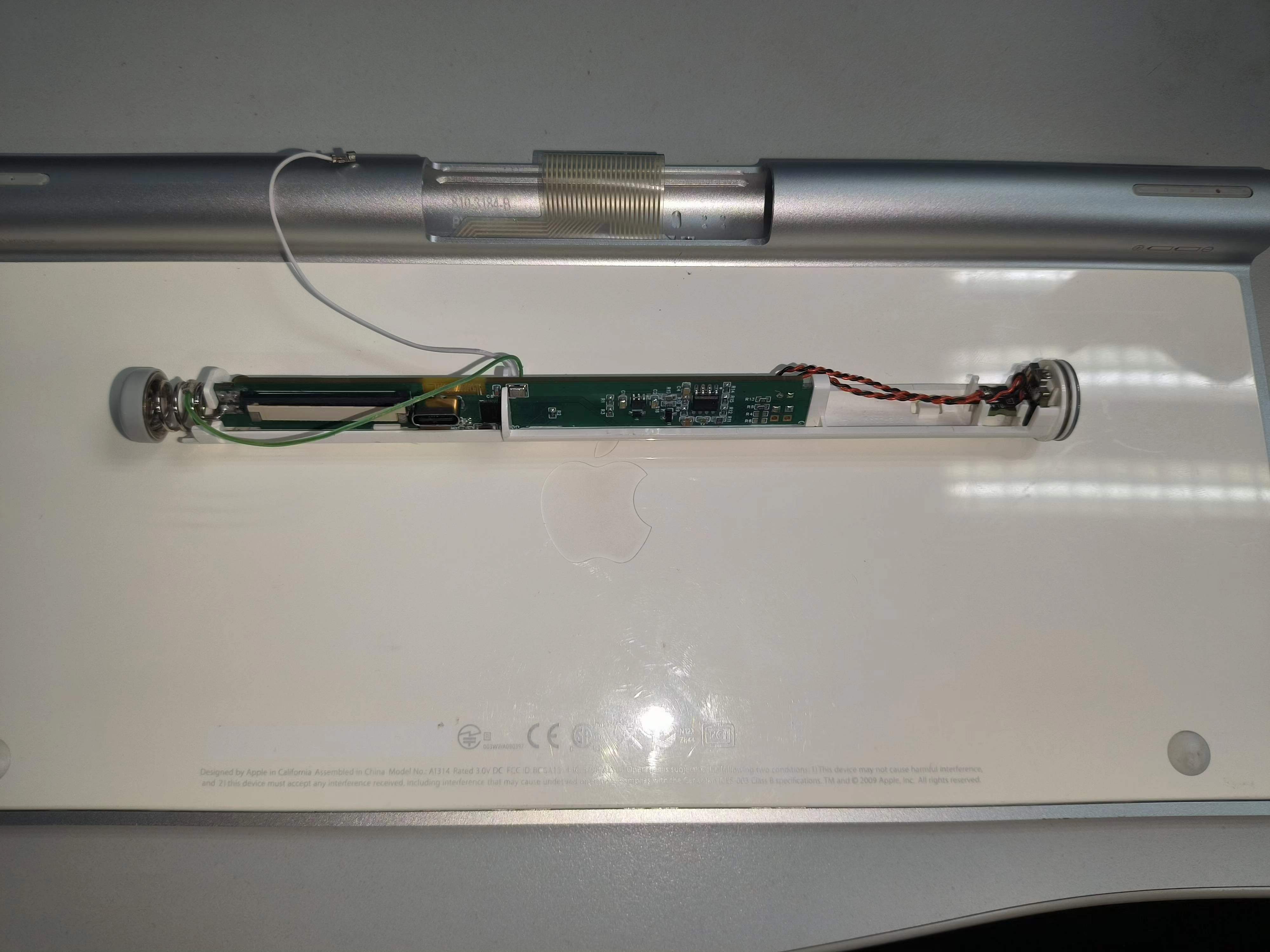
Magic A1314-pro-plus Tri-mode Keyboard
Magic A1314 keyboard modified into a tri-mode keyboard
The Magic A1314 keyboard has a decent appearance but average feel. Powered by two AA batteries, it's neither particularly useful nor a waste to throw away. It was used to test Qinheng's tri-mode keyboard solution.
Some of the project materials were provided by Qinheng. The actual project files consist of a receiver and a Magic A1314-Pro
receiver casing. I found the casing on the street; it didn't match the official board design, so I made some adjustments. I changed the LED pins, but everything else remained the same. Actually, I couldn't find any use for the LEDs in the firmware, so it's essentially unchanged.
I drew a three-LED light board, intending to use red, green, and blue indicators, but when coding, I found it useless, so I used the original LEDs. The actual code doesn't include lighting effects; I'll add
support for AA battery power later. However, when using AA batteries, do not plug in USB to avoid charging non-rechargeable batteries. I am not responsible for any consequences.
It supports AA rechargeable batteries and USB charging. Due to the Type-C female connector, the USB's forward and reverse insertion functions are inconsistent. Forward insertion provides power and USB communication; reverse insertion only provides power and not communication. Therefore, if you find no connection when using USB mode, try reversing the Type-C connector
. Key functions:
FN+Q: Connect via Bluetooth
FN+A: Connect via 2.4G
FN+Z: Connect via USB
FN+1/2/3/4: Switch Bluetooth devices (up to 4 hosts; Bluetooth names will be MK00_0/MK01_1...)
FN+0: Re-pair via 2.4G
FN+F1: Decrease screen brightness
FN+F2: Increase screen brightness
FN+F4: Open My Computer
FN+F7: Previous track
FN+F8: Pause
FN+F9: Next track
FN+F10: Mute FN+
F11: Decrease volume
FN+F12: Increase volume
-------------
The uses for F3 and the eject button are still undecided.
Firmware information:
https://gitee.com/feixiangjusha/miao-kong-a1314-pro-plus.git
PDF_MagicControl A1314-pro-plus Tri-mode Keyboard.zip
Altium Magic A1314-pro-plus Tri-mode Keyboard.zip
PADS Magic A1314-pro-plus Tri-mode Keyboard.zip
BOM_MagicControl A1314-pro-plus Tri-mode Keyboard.xlsx
93944
Smart Fun Dumbbells
A smart and fun dumbbell based on an STM32 microcontroller. This design utilizes the MPU6050 posture sensor to learn the user's desired movement. By monitoring posture angles and acceleration in real time, and combining this with voice feedback, it reminds the user to adjust to the correct exercise posture, thereby preventing sports injuries. Simultaneously,
This smart counting dumbbell is designed to provide fitness enthusiasts with a more convenient and effective workout experience, improving the standardization and accuracy of movements through intelligent technology. It features real-time feedback, data transmission, and recording functions, helping users better understand their workout progress and achieve optimal fitness results. The basic functions of the smart fun dumbbell are as follows:
Main Menu: After the motherboard powers on, the OLED screen displays the date and time, the weight of the currently installed weight plates, and the remaining battery power. Users can intuitively see the current time during workouts for convenient time management.
Workout Mode: Short press button 1 to enter workout mode. Users can continuously press button 1 to learn posture changes; the movements learned by the fun dumbbell will be considered ideal movements for subsequent workouts. After the dumbbell announces "Start exercising," when the user's subsequent movements reach the confidence range, the dumbbell will announce the count through the speaker and dump the workout data (date, cumulative repetitions, weight plates) for later retrieval. During exercise, long press button 2 can reset the data; short press button 2 again returns to the main menu.
Analysis Mode: Short press button 2 on the main menu to enter analysis mode. The OLED screen will display a bar chart of the past 14 days. When the voice recognition detects the keyword "analyze data," the dumbbell will provide suggestions and guidance to the user based on historical data. Short press button 2 to return to the main menu.
Edit Date: Press buttons 1 and 2 simultaneously to enter date and time editing mode. Short press button 1 to increment the current value; short press button 2 to decrement the current value; long press button 2 to cycle through the currently edited field. Long press buttons 1 and 2 simultaneously to return to the main menu.
Invincible Version 1.0.zip
PDF_Smart Fun Dumbbells.zip
Altium Smart Fun Dumbbells.zip
PADS_Smart Fun Dumbbells.zip
BOM_Smart Fun Dumbbells.xlsx
93945
[Electrical Engineering Competition Module] TPS5450 Step-Down Module
TPS5450 High Current Step-Down Module
Chip Description: TPS5450 The
TPS5450 is a high-output-current PWM converter; it integrates a low-resistance high-side N-channel MOSFET.
It features undervoltage lockout, slow start, and voltage pre-feedback circuitry; when EN is off, the current can be reduced to 18uA.
Electrical Characteristics:
Input voltage range 5.5V~36V;
Up to 5A continuous output current;
Output voltage 1.22V~30V;
Circuit Description:
A 5.082P terminal block is used as the main input and output interface of the module, and a 2.543P header interface is added for extended power input and output for ease of use;
According to the capacitor distribution in the datasheet, two 4.7uF capacitors and one 10nF capacitor are used for filtering at the input; a 300uF capacitor and a 100nF capacitor are used for filtering at the output; The
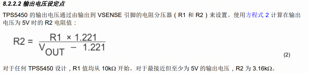
output voltage is adjusted by adjusting the voltage divider values of R1 and R2;
Precautions:
As described in the datasheet, this chip has a maximum output current of 5A, making it a high-current output DC-DC chip. When designing the PCB, if a current exceeding 3A is required, it is recommended to perform a solder mask opening and tin plating on the copper trace. In this example, no opening and tin plating were performed for aesthetic reasons;
When selecting voltage divider resistors, it is not recommended that the accuracy be lower than 1%, and the feedback line needs special consideration;
PCB layout should ideally follow the datasheet, with inputs, outputs, and chip GND all on a single copper trace. In this example, there are no other components, and the bottom copper trace is intact; therefore, some layout choices were omitted for aesthetic reasons.
Capacitor voltage ratings must be correctly selected; otherwise, they may burn out under high voltage input. Note
in the measured image
that 5V output at 1A is already 5W; therefore, you should connect multiple ordinary resistors or cement resistors in parallel to prevent them from burning out.


PDF_【Electronic Design Contest Module】TPS5450 Step-Down Module.zip
Altium_ [Electronic Design Contest Module] TPS5450 Step-Down Module.zip
PADS_【Electrical Engineering Competition Module】TPS5450 Step-Down Module.zip
BOM_【Electronic Design Contest Module】TPS5450 Step-Down Module.xlsx
93946
electronic
 Combination section:
  Power supply section:


 京公网安备 11010802033920号

 54121-418-35-0900


