The IP5407
is a multi-functional power management SoC integrating a boost converter, lithium battery charging management, and battery level indicator, providing a complete power solution for power banks. Its high integration and rich functionality require very few external components, effectively reducing the overall solution size and BOM cost. The IP5407 uses only one inductor to achieve both buck and boost functions, supporting low-cost inductors and capacitors. The IP5407's synchronous boost system provides 2.1A/2.4A output current with a conversion efficiency of up to 93%. Under light load, it automatically turns off the LED power indicator and maintains a 5V output voltage to enter sleep mode, with the quiescent current dropping below 150uA. The IP5407 uses switching charging technology, providing 2.0A input current with a charging efficiency of up to 91%. Built-in IC internal temperature and input voltage detection intelligently adjust the charging current. The IP5407 supports 4, 2, and 1 LED power display and illumination functions. The IP5407 is packaged in an ESOP8.
The LGS63030EP
is a boost DC-DC LED driver chip with an integrated power switch and a wide input voltage range of 3V to 60V. It integrates soft-start, minimizing the need for external surge suppression components, making it ideal for driving LEDs with a wide input power range. The output current can be adjusted via an external resistor. The LGS63030EP features an integrated 350mΩ power switch, providing at least 1.5A of peak input current capability, and excellent load and line transient response. It features a SKIP control mode, combining low quiescent current with a high switching frequency for high efficiency over a wide load current range. Additional features include: soft-start, adjustable output overvoltage protection, thermal shutdown, UVLO undervoltage lockout, and cycle-by-cycle peak current limiting protection. The LGS63030EP allows for high-precision digital and analog adjustment of the output current by selecting different values of the sampling resistor RSence.
Regarding this project
: 1. Due to limited technical skills, the program was written using the graphical programming software Linkboy. The "FLASHLIGHT-PRE.lab" file in the attachment needs to be opened with this software.
2. For U5 (ATmega328P), it is recommended to buy an Arduino NANO and remove it from it. It not only comes with a built-in bootloader and is inexpensive, but also allows you to pre-program it, saving the need for C16, C22, C23, R14, and U6.
3. If you do not pre-program it, the LGS63030EP may be accidentally enabled. It is recommended to flash the program in advance, or temporarily short-circuit the 4 pins of the LGS63030EP to ground.
4. For U1, U2, and U3, you need to remove pin 2 of U1, pin 1 of U2, and pin 6 of U3.
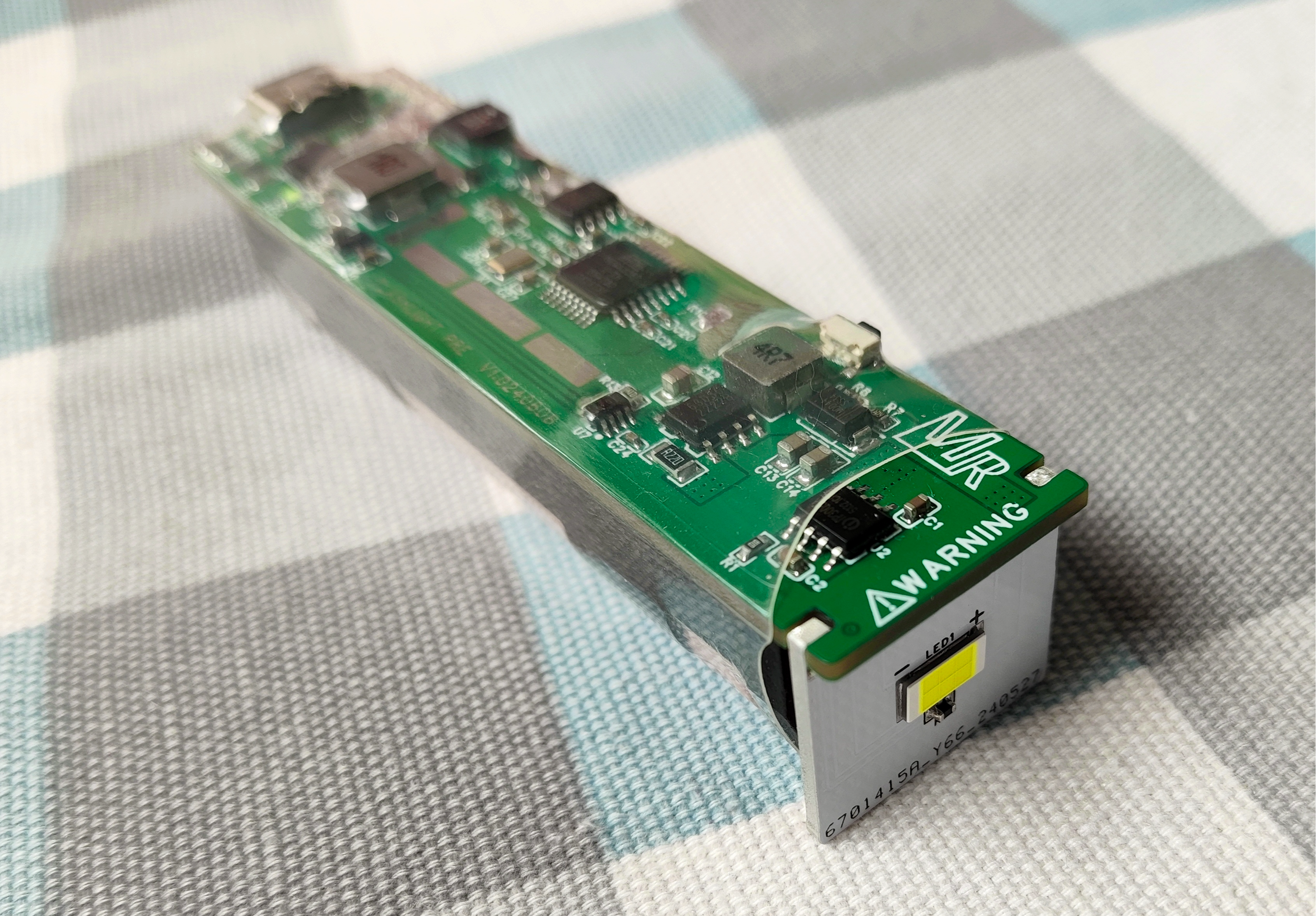
5. PCB1 is made of FR-4 substrate, and PCB2 is made of aluminum substrate. The back of PCB2 should face the battery box, and the pins on both sides should be aligned with the corresponding slots on PCB1. Then, use solder to connect the four solder points between the PCBs.
6. If using the program in the attachment, you need to press briefly and then press and hold for about 1 second to turn the device on or off.


 京公网安备 11010802033920号

 591D475X9050C4W20H


