With increasing environmental awareness and the development of renewable energy technologies, intelligent photovoltaic voice recognition sorting trash cans have emerged. The significance of this project lies in improving the efficiency and accuracy of trash sorting, reducing manual operation costs, promoting resource recycling, and reducing environmental pollution. This project combines multiple advanced technologies, realizing the application of green energy while utilizing intelligent voice recognition technology, temperature and humidity detection, and infrared overflow technology to enhance the intelligence level of trash sorting. The intelligent trash can can identify the type of trash based on voice commands, guiding users to correctly sort it, thus contributing to environmental protection.
1. Project Description:
The photovoltaic intelligent voice recognition sorting trash can is a product that combines environmental awareness and renewable energy technology, aiming to improve the efficiency and accuracy of trash sorting while reducing manual operation costs. This product uses solar energy as its primary energy source, providing stable power to the trash can and its electronic equipment through photovoltaic panels and solar charging modules, fully demonstrating the application of green energy.
In terms of hardware design, the product uses an STM32 microcontroller as the central control unit, combined with a voice recognition module and an infrared sensing module to achieve intelligent trash sorting. The power supply module design considers power requirements, ensuring the reasonable selection of solar panels, inverters, controllers, and batteries, and the design of the power system. The actuator module controls the opening and closing of the trash can lid via a servo motor, responding to voice commands to ensure correct trash disposal.
In terms of programming, the product uses a voice module to recognize wake-up words and classification terms, such as "recyclable waste," "hazardous waste," "kitchen waste," or "other waste," and executes corresponding instructions based on the recognition results. The system incorporates a feedback mechanism; when the trash can is full, an indicator light illuminates to remind users to empty it, ensuring continuous use and maintenance.
Ultimately, the photovoltaic intelligent voice recognition sorting trash can not only provides an intelligent solution for trash sorting but also promotes resource recycling and reduces environmental pollution through its convenience and environmental friendliness. With the further development of artificial intelligence, green energy, customized design, community participation, and IoT and big data technologies, this product has broad application prospects and is expected to become an important tool for future intelligent trash sorting.
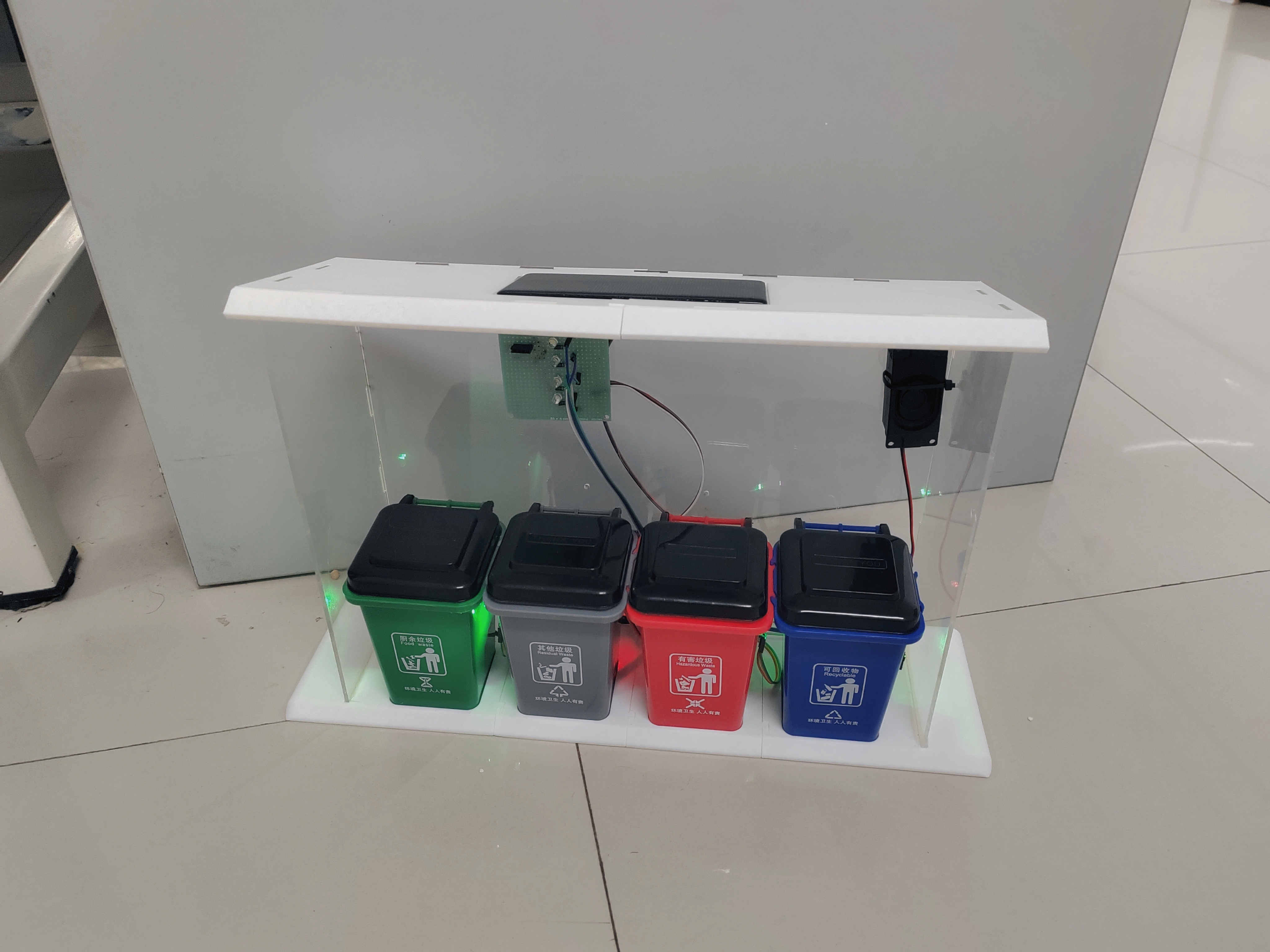
[Image 2: Final product of the intelligent photovoltaic voice sorting trash can
] Project Features:
The photovoltaic intelligent voice recognition sorting trash can is a product integrating environmental protection concepts, renewable energy technology, intelligent voice recognition, automated control, and IoT technology. Powered by solar energy and precisely managed by an STM32 microcontroller, it achieves automated and intelligent trash sorting while also possessing the potential for community participation and customized design.
In response to national policies, photovoltaic power generation is a necessary pathway to achieving carbon neutrality. Therefore, "photovoltaics" is incorporated into the design concept of this product, enabling voice-activated waste sorting to ensure the rational reuse of resources. Currently, smart trash cans are not yet widely available in China. The "photovoltaic smart trash can" brand boasts strong market penetration, a powerful impact, and significant market appeal. Furthermore, its ultra-low-price direct supply, superior product quality, continuous new product launches, and positive reputation for social service have secured its leading position in the market.
The photovoltaic smart voice-activated waste sorting trash can utilizes an STM32 microcomputer control chip, intelligent voice recognition, photovoltaic power generation, an infrared overflow device, a mechanical transmission device, and a linkage mechanism. With its automatic lid opening and closing, it is a high-tech new product integrating mechanics, optics, and electronics, offering advantages such as reliable performance, long service life, and low power consumption. Simultaneously, the system's host computer uses mobile and computer terminals for centralized management, monitoring the real-time status of the trash cans and providing auxiliary decision-making for sanitation bureaus' garbage truck routes, effectively improving the operational efficiency of garbage trucks.
Intelligent sensor-operated garbage stations/bins allow people to dispose of garbage without touching any part of the bin, preventing cross-contamination, promoting environmental hygiene, and boasting an attractive appearance. They require no external power supply, using photovoltaic cells for energy efficiency and eliminating the need for wiring. Their excellent sealing performance reduces the chance of cross-infection from various germs, prevents odor overflow, and ensures fresh air. Intelligent voice-activated sorting and recognition prevents incorrect garbage disposal, reducing the workload of sanitation workers.
3. Project Production Process
1. Schematic Design
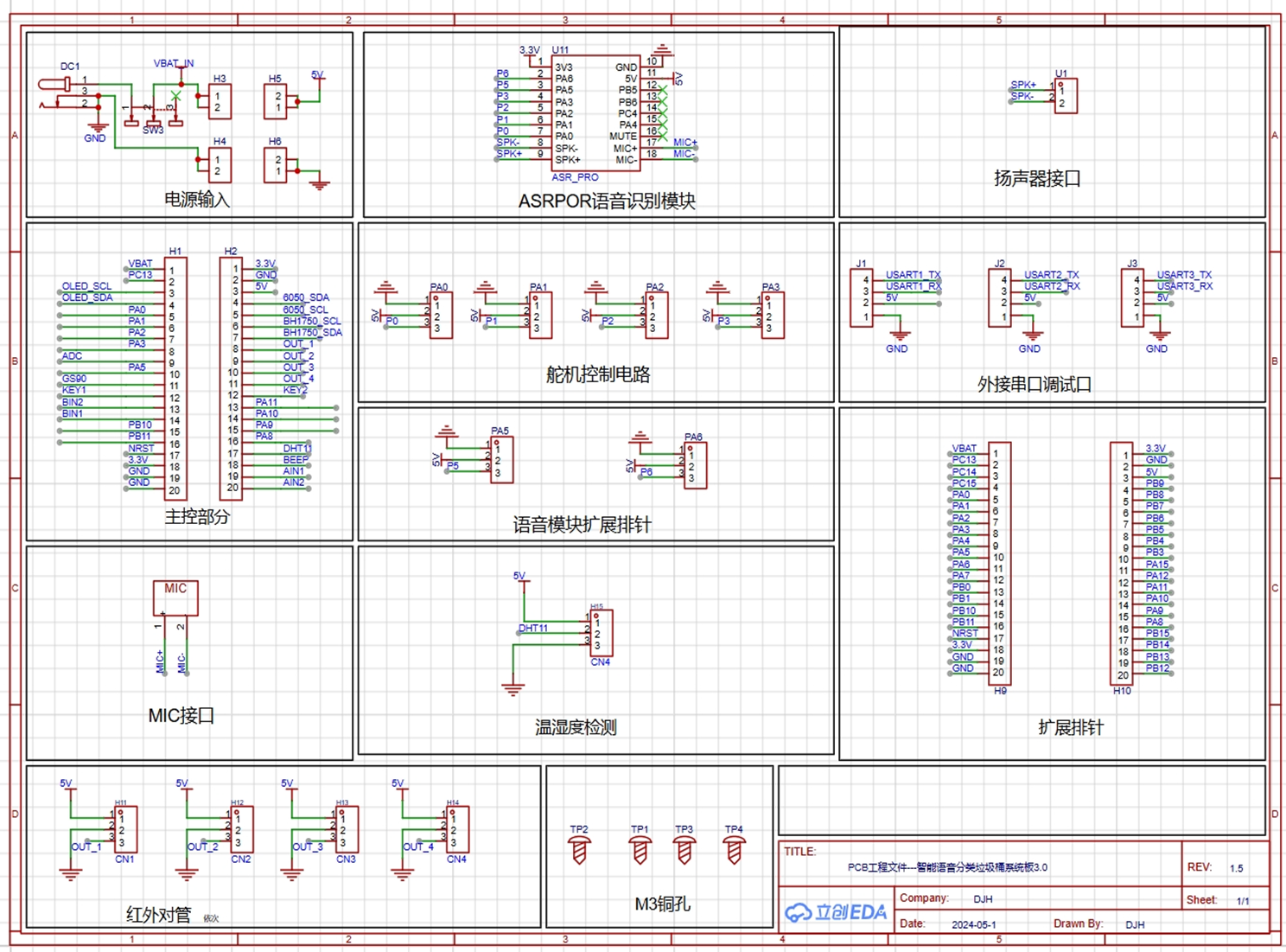
The above is the schematic diagram of this product. This project uses the STM32F103C8T6 as the main control chip, paired with a voice recognition module, an infrared recognition module, and a DHT11 temperature and humidity detection module, enabling functions such as voice control recognition, garbage bin overflow detection, and temperature and humidity display.
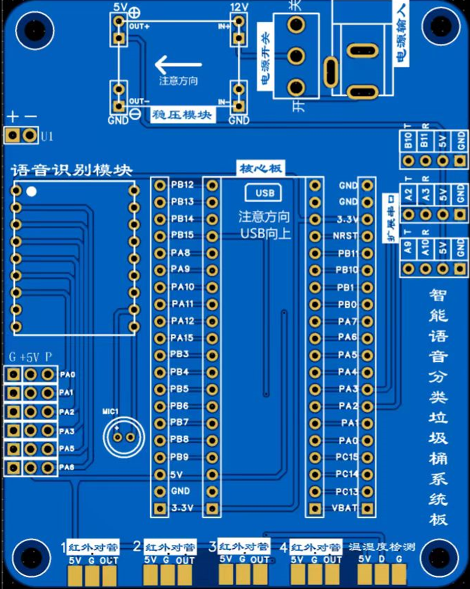
2. PCB Design
860a356e9fef789b0c6a00cdaa9b8d8a.mp4
2d70b9da8676fc03869f3cba9d9a4f24.mp4
PDF_Intelligent Voice-Controlled Trash Can System Board 3.0.zip
Altium Smart Voice-Controlled Trash Can System Board 3.0.zip
PADS_Intelligent Voice-Controlled Trash Can System Board 3.0.zip
BOM_Intelligent Voice-Controlled Trash Can System Board 3.0.xlsx
94019
Smart lighting fixtures controlled via mobile phone WiFi
No WiFi firmware development, no APP development, and no cloud server development are required. Once the mobile phone connects to the chip's WiFi, the brightness and color temperature of the light can be adjusted.
This project is a
school electronics technology internship. The initial design was done in Altium Designer (AD), and later redesigned using JLCPCB. The number of components used is relatively small, and the finished product is not difficult.

1. Project Description
1.1 Project Overview
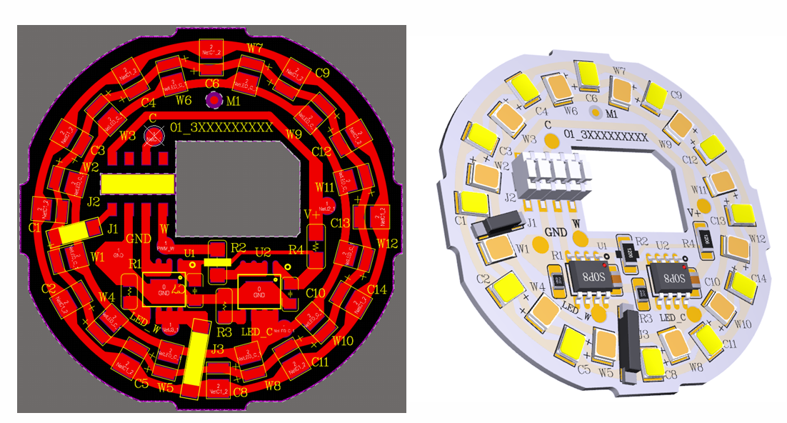
This project uses 12 yellow and 12 white LEDs, along with a BL-M5-WIFI wireless module. Product development is possible without requiring WIFI firmware development, APP development, or cloud server development.
1.2 Project Functionality

After the PCB is fabricated, soldered, and debugged, connect the power supply. Download Magic Home Pro on your phone, connect to the chip's WiFi (LEDnet***), and you can control the bulbs from your phone.
1.3 Physical Demonstration

(Functional demonstration at the end
) 2. Hardware Description
2.1 Power Supply & Wireless Board
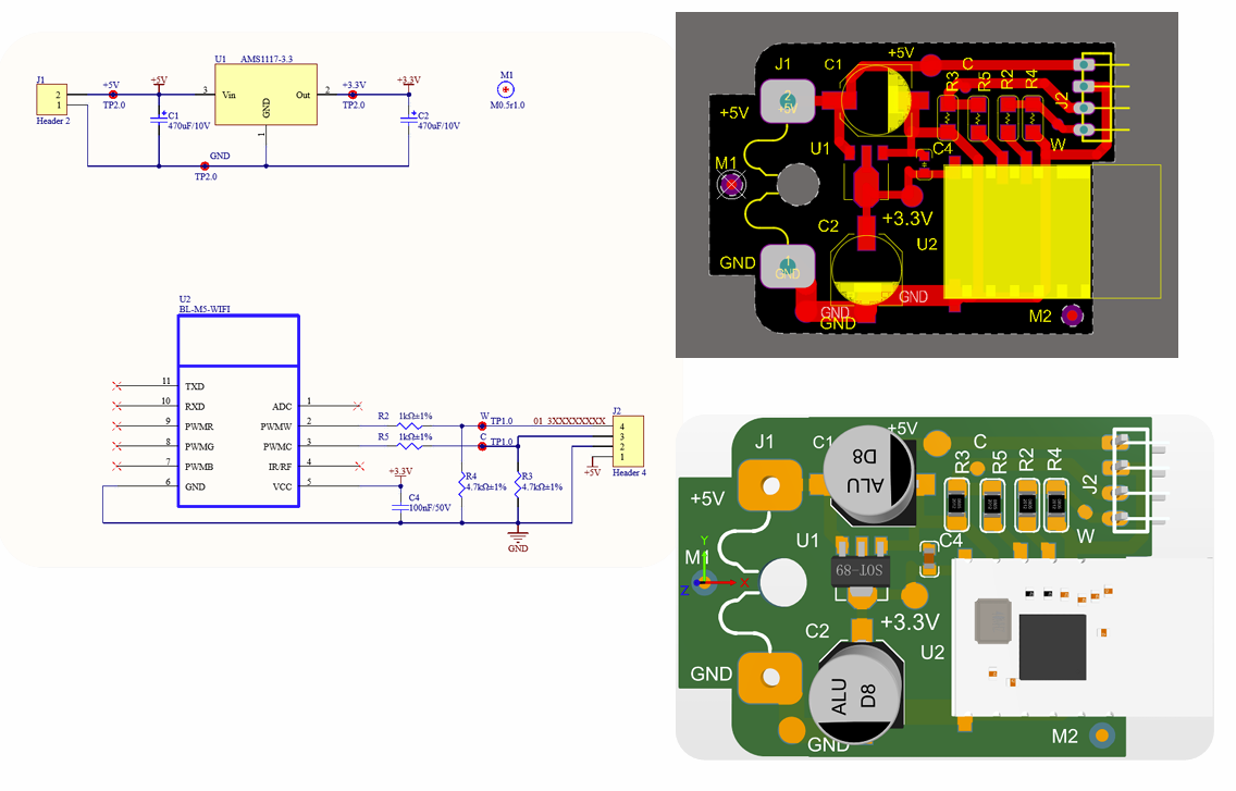
1) Wireless Module BL-M5-WIFI, model BL-M5_L52_CCT, PWMW is a warm white PWM output, PWMC is a cool white PWM output, connected in series with a current-limiting resistor and a pull-down resistor.
2) AMS1117-3.3, converts 5V to 3.3V.
2.2 Lamp Board

1) SM15633E, a three-channel LED constant current driver control chip, can achieve dimming of OUT1/2/3 ports by inputting PWM signals through DIM1/2/3 ports respectively.
2) Surface Mount Single Row Female Socket GL04B008SFR-002 (4P2.0), which can be paired with the power board to provide power and PWM wave to the lamp board.
3) QM52, QM82, two different sizes of jumpers. Because this project will teach PCB etching later, the PCB can only be drawn on one layer. Jumpers are used for places where it cannot be drawn.
4) Surface Mount LED2835WA cool white light, Surface Mount LED2835EA warm white light
. 3. Instructions for Use
The casing is provided by the school. You need to find a USB cable to solder the 5V and GND pads on the power board. After powering on, you need to download the APP (Magic Home Pro download address) to control the brightness and color temperature.
The attachment contains the component manuals for the lamp board, power supply & wireless board. The course materials teach how to draw those two boards in AD.
Lamp Board Component Manual.7z
Power Supply & Wireless Board Component Manual.7z
Courseware materials.zip
Effect demonstration.mp4
PDF_Smart Lighting Fixtures Controlled by Mobile Phone WiFi.zip
Altium Smart Lighting Fixtures Controlled via Mobile WiFi.zip
PADS_Smart Lighting Fixtures Controlled by Mobile Phone WiFi.zip
BOM_Smart Lighting Fixtures Controlled by Mobile WiFi.xlsx
94020
AHT20+BMP280 stm32 temperature, humidity and barometer
This holiday was relatively relaxed, so I planned to upgrade my existing ideas and create a portable, rechargeable handheld tool that can simultaneously calculate temperature, humidity, air pressure, and altitude. I'll call it "The Lost Records".
I originally planned to build a 51 microcontroller-driven thermometer and hygrometer at the end of last semester. Due to various reasons, I didn't start. This holiday is relatively free, so I plan to upgrade my original idea and build a portable, rechargeable handheld tool that simultaneously calculates temperature, humidity, air pressure, and altitude. I'll call it "The Lost Records."
I'll use an STM32 as the computing unit and
the K5 editor and St Linkv 2.
The driver provided by the vendor for the AHT20+BMP280 module had a problem; one instruction was incorrect. I've fixed it, and it can read the temperature and humidity successfully.
Except for this module, the rest of the code is taken from the Bilibili channel of Jiangsu University of Science and Technology. This includes the LED lights, button acquisition, OLED screen, and Ad.
The PC13 port sends a low-level signal every 16 seconds to activate the external CD42 charging/discharging module. (Because this module will shut down after 30 seconds when the discharge current is less than 50 mA, the microcontroller continuously sends signals to keep it alive.)
All the code is in the "Completely Good" folder; please also refer to the "Instructions" document. Other files are process documents that you can download as needed.
The schematic and PCB files are also open-sourced here at JLCPCB.
The hardware uses a layered pin header system, connecting each module. All fasteners are directly soldered. Copper pillars and screws are used to accommodate the removability of the top panel and bottom battery base plate. Eight pin headers are used for the connection between the panel layer and the center.
Please leave a comment if there are any unclear points. With the physical prototype, schematic, and code, you should be able to fully understand my approach. The variable names and comments in the code are legible.
Link: https://pan.baidu.com/s/1_AI39Hh_vyOWYeXK8i8FXw?pwd=good The attached files are the same.
Extraction code: good
Lost Records - Temperature, Humidity, Barometer, and Altimeter.zip
PDF_AHT20+BMP280 stm32 Temperature, Humidity and Barometer.zip
Altium_AHT20+BMP280 stm32 Temperature, Humidity and Barometer.zip
PADS_AHT20+BMP280 stm32 Temperature, Humidity and Barometer.zip
BOM_AHT20+BMP280 stm32 Temperature, Humidity and Barometer.xlsx
94023
[USB Network Adapter] USB 3.0 2.5G speed USB network adapter
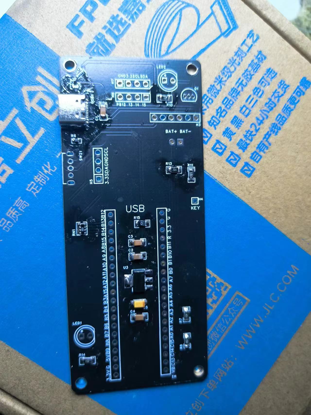
This USB network adapter uses the RTL8156B to implement USB 2.5G network adapter functionality.
Physical Product Images

Hardware Design
Interface Design
USB Interface: Utilizes a USB 3.0 interface to ensure sufficient bandwidth to support 2.5Gbps network transmission speeds. The interface design should be compatible with mainstream operating systems and USB standards.
Network Interface: An integrated transformer is selected to adapt to 2.5Gbps transmission speeds. The interface should support full-duplex communication and auto-negotiation.
Main Control Chip
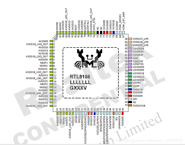
1. The Realtek RTL8156B-CG/RTL8156BS-CG is a 10/100/1000M/2.5G Ethernet controller combined with a quad-speed IEEE 802.3 compliant media access controller (MAC), featuring a quad-speed Ethernet transceiver, USB 3.0 bus controller, and embedded memory, employing advanced digital signal processor technology and mixed-mode signal technology.
2. The RTL8156B-CG/RTL8156BS-CG provides high-speed wired network transmission via Category 5e UTP cable or Category 3 UTP (10Mbps only). Supports cross-detection and automatic correction, polarity correction, MDI switching, adaptive equalization, crosstalk cancellation, echo cancellation, timing recovery, and RF interference protection, providing robust transmission and reception capabilities through management, loopback diagnostics, and error correction.
3. The RTL8156B-CG features an embedded one-time programmable function (OTP) to replace external EEPROM memory (93C46/93C56/93C66), while the RTL8156BS-CG provides a built-in switching regulator.
4. The RTL8156B-CG/RTL8156BS-CG utilizes USB 3.0, offering higher bandwidth and improved data protocols for exchange between host and device. USB 3.0 also provides advanced power management and energy-saving features.
5. The RTL8156B-CG complies with IEEE 802.3u specifications: IEEE 802.3ab specifications for 10/100Mbps Ethernet and 1000Mbps Ethernet, and IEEE 802.3bz 2500Mbps Ethernet specifications. Both support efficient power management. In addition to ACPI features, both support remote wake-up (including AMD Magic Packet and Microsoft Wake-up Framework), ACPI, and APM (Advanced Power Management) environments.
6. The RTL8156B-CG/RTL8156BS-CG supports Microsoft Wake-up Packet Detection (WPD), providing wake-up frame information from the operating system, such as PatternID, OriginalPacketSize, SavedPacketSize, SavedPacketOffset, etc. WPD helps prevent accidental/unauthorized wake-ups of a sleeping computer.
7. The RTL8156B-CG supports "RealWoW!". This feature allows the PC to reduce power consumption by maintaining a low-power sleep state. Note: The "RealWoW!" service needs to be registered upon first use.
8. The RTL8156B-CG supports protocol offloading. It offloads some of the most common protocols to the NIC hardware to prevent spurious wake-ups and further reduce power consumption.
9. The RTL8156B-CG/RTL8156BS-CG can offload ARP (IPv4) and NS (IPv6) protocols in D3 power-saving mode.
The SOC module

references a 2.5G network card based on the RTL8156B chip using the USB 3.0 protocol – JLCPCB EDA open-source hardware platform (oshwhub.com), with the main chip design based on RTL8156+VL822+FE2.1 (fully verified) – JLCPCB EDA open-source hardware platform (oshwhub.com), and modifications have been made.
The USB interface module
![]()
uses a USB 3.0-A interface, requiring no external components. RX and TX can be directly connected to the SOC's TX and RX. (The SOC has a series capacitor.)
The network interface module
![]()
uses an independent transformer and an RJ45 port. Using an independent transformer is cheaper, although it increases the board design complexity compared to an integrated RJ45 and transformer design. (A separate transformer will be available later, with even lower costs).
The network port impedance is 90Ω differential, with a trace width of 9.3mil, a trace spacing of 5mil, and a ground plane spacing of 5mil. (The trace width may be slightly narrower depending on the actual routing.)
The PCB design
uses a two-layer board design, employing coplanar impedance ground planes for impedance control. (Actual measurements have not been taken; impedance cannot be controlled using free prototyping.)
The magnitude of the coplanar impedance is highly dependent on the trace width and ground plane spacing. The smaller the ground plane spacing and the wider the trace, the smaller the distributed capacitance and the higher the impedance.
The power supply design

uses one DC-DC converter and one LDO to provide the power required by the SOC.
The DC-DC converter uses an RT8096 with a 0.9V output. The output voltage calculation is 0.9 = 0.6(1 + 5/10). A 3.3uH inductor is used, but a 1uH inductor would be more suitable for 0.9V. A 10uH output capacitor is used according to the datasheet.
The LDO uses an RT9080-33GJ5 with a fixed output voltage of 3.3V; no other external components are required.
The exterior design
is currently unavailable; the casing is still under design. (Hoping to complete this with expert help, as I am not skilled in modeling). More data will be added
later . Expected Outcome: A stable and reliable USB 2.5G network card product that meets the needs of high-speed network transmission. Detailed hardware design documents and test reports for developers' reference and learning. An open hardware design platform and community support to promote innovation and development in network hardware technology.
PDF_【USB Network Adapter】USB 3.0 2.5G Speed USB Network Adapter.zip
Altium_ [USB Network Adapter] USB 3.0 2.5G speed USB network adapter.zip
PADS_ [USB Network Adapter] USB 3.0 2.5G speed USB network adapter.zip
BOM_【USB Network Adapter】USB 3.0 2.5G Speed USB Network Adapter.xlsx
94024
Hand-built 8-bit computer: Z80-V2
Hand-built 8-bit computer
hardware: motherboard, LED array, graphics card, sound card, game controller, memory, CF card, serial port.
Functions:
1. Supports running games from the SG1000 game console with a capacity of 32KB.
2. Supports running the CP/M operating system.
The design and debugging of the entire system's hardware and software took about a year and a half, during which many difficulties were encountered, but fortunately, they were all resolved one by one.
This project will be one of the best practical projects in computer organization principles: it adopts a modular design, with each module having a clear division of labor and a simple structure, allowing modules to be added or removed as needed.
The minimum system requires at least three modules: a motherboard, memory, and an LED array. With these three boards, it is possible to run self-made programs and observe their output, which is also the part that must be done in the early stages of the project.
Video:
CP/M Demo: https://www.bilibili.com/video/BV1BxGkeuEWK
I will be uploading hardware and software tutorials for this project to bilibili gradually. Follow me for the latest updates: https://space.bilibili.com/252130017
Software:
To download the code, please copy the following command to your terminal and execute it: git clone https://gitee.com/tomorrow_land/z80v2.git
Hardware:
Z80-VDP Graphics Card
Z80-MEMORY Memory
Z80-JOYPAD-PSG Game Controller + Sound Card
Z80-DIGITAL I/O LED Array
Z80-KEYBOARD PS/2 Keyboard
Z80-SIO RS232 Serial Port
Z80-CF Compact Flash Memory Card
For this replica project, please strictly adhere to the open-source license terms. Note: Information related to the project and author in the PCB board and source code must not be modified, including text and logos.
Open Source License: GPLv3

PDF_Manually Hand-crafted 8-bit Computer: Z80-V2.zip
Altium - Hand-crafted 8-bit computer: Z80-V2.zip
PADS 8-bit Hand-crafted Computer: Z80-V2.zip
BOM_Manually Built 8-bit Computer: Z80-V2.xlsx
94025
[Mini Project] STM32 Electronic Keyboard and Bluetooth Music Player
This project is a Bluetooth music spectrum lamp and electronic keyboard based on the STM32F103RCT6 chip. The Bluetooth speaker itself can be solved by pure hardware, but in order to show the workload, a microcontroller, TFT screen, ADC module and other functions were added.
This work is a modified version of an open-source project by a master programmer, and some issues remain, as mentioned in the attached "Introduction." However, it is sufficient for a microcontroller course project or learning project. The original
open-source project link
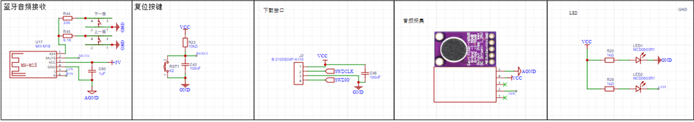
begins with the TPA3116 power amplifier circuit, the core component, which connects to the speakers for sound output.

The power supply section

contains some miscellaneous components; these are mainly for connecting to the 32-bit chip.
The Bluetooth module, audio acquisition module, and TFT screen can be purchased from Taobao. The Bluetooth module has a built-in song switching function; simply connect it according to the resistor values. The audio module outputs analog signals, which need to be converted using the ADC pin of the 32-bit chip. The TFT uses hardware SPI, so find the correct SPI pin on the 32-bit chip (configure directly using CubeMX).

Next is the 32RCT6. The reason for choosing this chip is its fewer pins for easier soldering, and because a DAC function is required. The RCT6 chip was selected based on the table below.
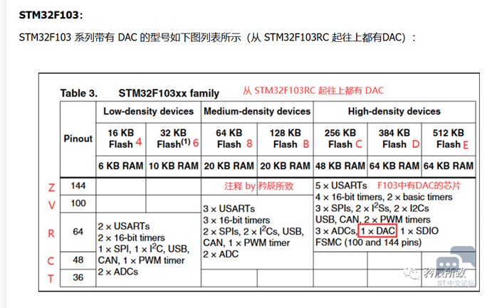
Remember the components you learned before? Connect them to the pins (the pin positions are your choice; details will be explained in the CubeMX configuration

section later). I won't go into detail about the software; interested readers can download the attached "Introduction" and code package and refer to them.
Component purchase instructions:
Surface mount components are mostly 0603 packages. Use two resistors to divide the voltage to obtain 6V. I chose 0805 packages; you can choose to solder either 0805 or 0603.
For the RCT6 chip, TFT screen, MH-M18 Bluetooth module, and MAX9814 audio acquisition module, just find stores with high sales volume on Taobao.
The C1 and C5 capacitors are CBB packages; if you don't want to buy them separately, you can use ordinary capacitors.
I bought a six-pin 50k rotary potentiometer.
Finally, thanks to everyone who shared their learning experience in open source. I learned a lot during the process. Although the result isn't perfect, it's sufficient for a microcontroller course project.
It's less of a project and more of a review of my learning experience, haha (a little self-deprecation).
There are two versions! The second version is based on the problems in the first version, so just treat the first version as a joke.
9d7a3c6d9562858699c4f703d5089332.mp4
Introduction.docx
Bluetooth speaker.zip
Bluetooth speaker.7z
PDF_【Mini Course Project】STM32 Electronic Keyboard and Bluetooth Music Player.zip
Altium_【Mini Course Project】STM32 Electronic Keyboard and Bluetooth Music Player.zip
PADS_【Mini Course Project】STM32 Electronic Keyboard and Bluetooth Music Player.zip
BOM_【Mini Course Project】STM32 Electronic Keyboard and Bluetooth Music Player.xlsx
94026
Wireless Dual-Core Download Debugger ARM+RISC-V WCH-LinkW
A DAP downloader based on the CH32V208G supports both ARM and RISC-V wireless download methods.
Current version 1.1V
1. Fixed silkscreen error at the interface (TDX-->>TXD)
Current version 1.0V
1. Updated the test history in the data package
2. Online firmware upgrades may fail and firmware may be lost; in this case, the firmware needs to be reflashed.
The data has been uploaded as an attachment. If you have any questions, please leave a message at the bottom.
Video address: [Open Source] Hands-on Guide to Making a Mini Dual-Core Wireless Download Debugger ARM+RISC-V WCH-LinkW
Project Introduction
WCH-LinkW is a wired/wireless 2.4G dual-analog debugger that can be used for online debugging and
downloading , and also for online debugging and downloading of ARM chips with SWD/JTAG interfaces.
Mode
Status Indicator
Supported IDEs
Supported Chips
RISC-V
Blue light is off when idle
Mount River Studio
This company supports RISC-V core chips for single/dual-wire debugging
ARM
Blue light is on when idle
Keil/Moun River Studio
Supports ARM core chips with SWD/JTAG interfaces
For other models, please refer to the WCH-Link manual in the attachment.
The design has been reduced in size, making it more compact. A power pad is provided on the bottom for connecting an external power supply cable.
It adopts a 4-layer board design and uses a more professional CA-C03 antenna.
An acrylic protective shell is included to protect the downloader.
To save costs, I opted for hand soldering with a heating table. The chip was the most difficult part to solder; the rest was relatively easy to solder by hand. (Try challenging your soldering skills!) The wired
mode
requires only one WCH-LinkW. Connect the header pins to the MCU and the USB port to the computer for downloading and debugging.
The wireless mode requires two WCH-LinkWs: a WCH-LinkW master (connected to the computer) and a WCH-LinkW slave (connected to the MCU).
The wireless access address can be set using the WCH-LinkUtility tool.
Detailed parameter settings are provided in the attached WCH-Link user manual.
Instructions for Use
: Follow these steps using the attached data package:
Install the WCH-LINK driver package in administrator mode.
Press and hold BOOT and then power on. To burn the WCH-LINK firmware,
press and hold the Mode button and then power on. This will switch between ARM and RISC-V modes. In ARM mode, the blue light will remain constant.
In wireless mode, pre-set the current burning mode. Then, power on the slave (connected to the target chip) burner first, and then power on the host (connected to the PC) burner. When you see the green lights on both burners constantly lit, it indicates that you are in wireless download mode.
Test Progress:
[x] Wired Download Test
[x] Wireless Download Test
Physical Demonstration

Precautions
: 1. When soldering, please pay attention to the soldering order to ensure the power supply is correct and to avoid burning out subsequent circuits! The soldering order should follow the principle of from shortest to smallest, and from inside to outside.
2. The circuit has been verified. Solder according to the component parameters in the schematic diagram. It is recommended to solder the main controller first, as it is more difficult to solder. It is recommended to use a heated soldering station.
3. When using the board cleaning solution, be careful not to touch the buttons, as corrosion will make it difficult to use.
4. It is recommended to use the schematic diagram parameters; the BOM table may contain errors.
WCH-LinkW.zip
PDF_Wireless Dual-Core Download Debugger ARM+RISC-V WCH-LinkW.zip
Altium Wireless Dual-Core Downloader and Debugger ARM+RISC-V WCH-LinkW.zip
PADS Wireless Dual-Core Downloader and Debugger ARM+RISC-V WCH-LinkW.zip
BOM_Wireless Dual-Core Downloader and Debugger ARM+RISC-V WCH-LinkW.xlsx
94027
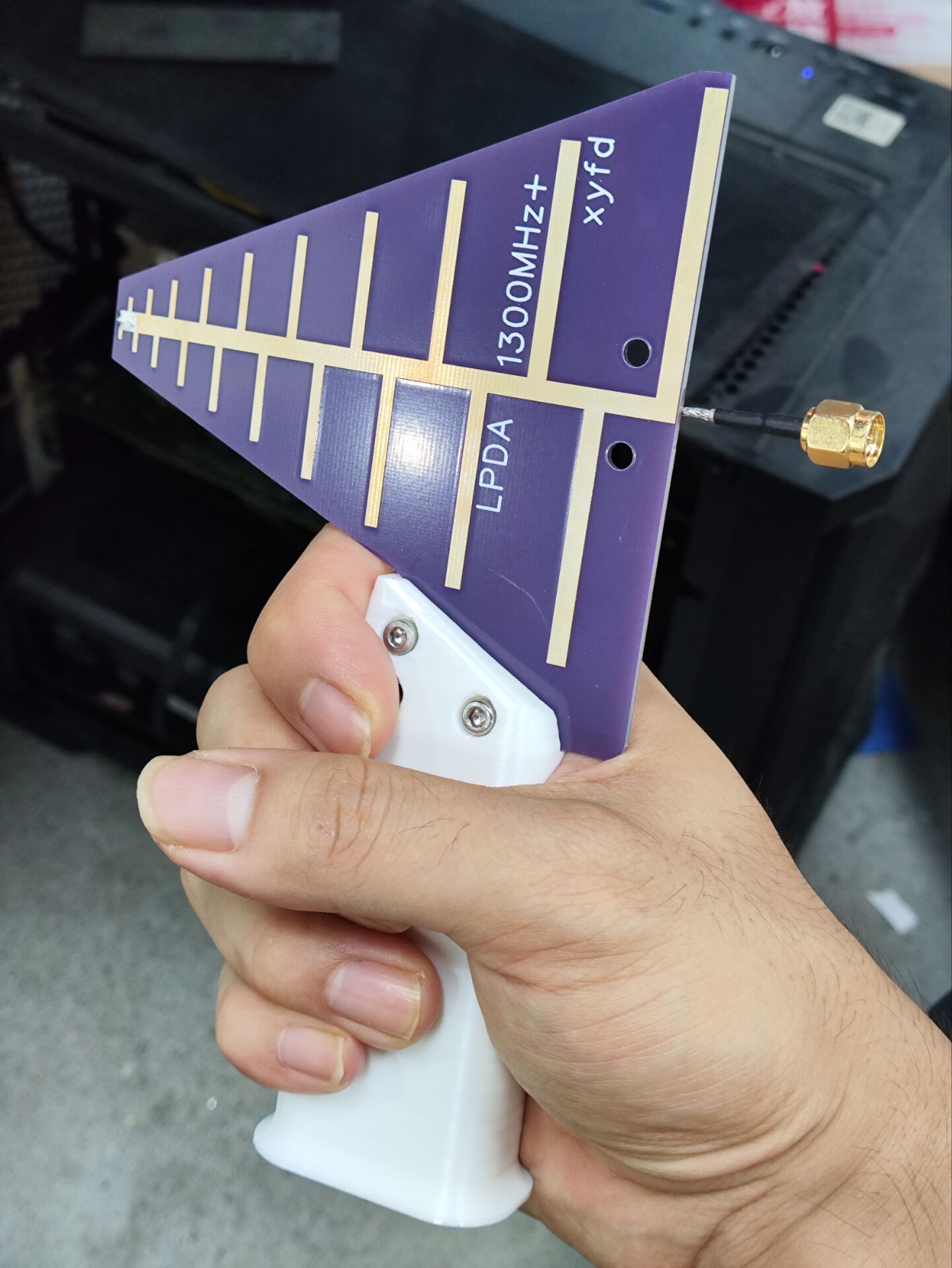
Log-periodic antenna, operating frequency above 1300MHz, comes with handle model file.
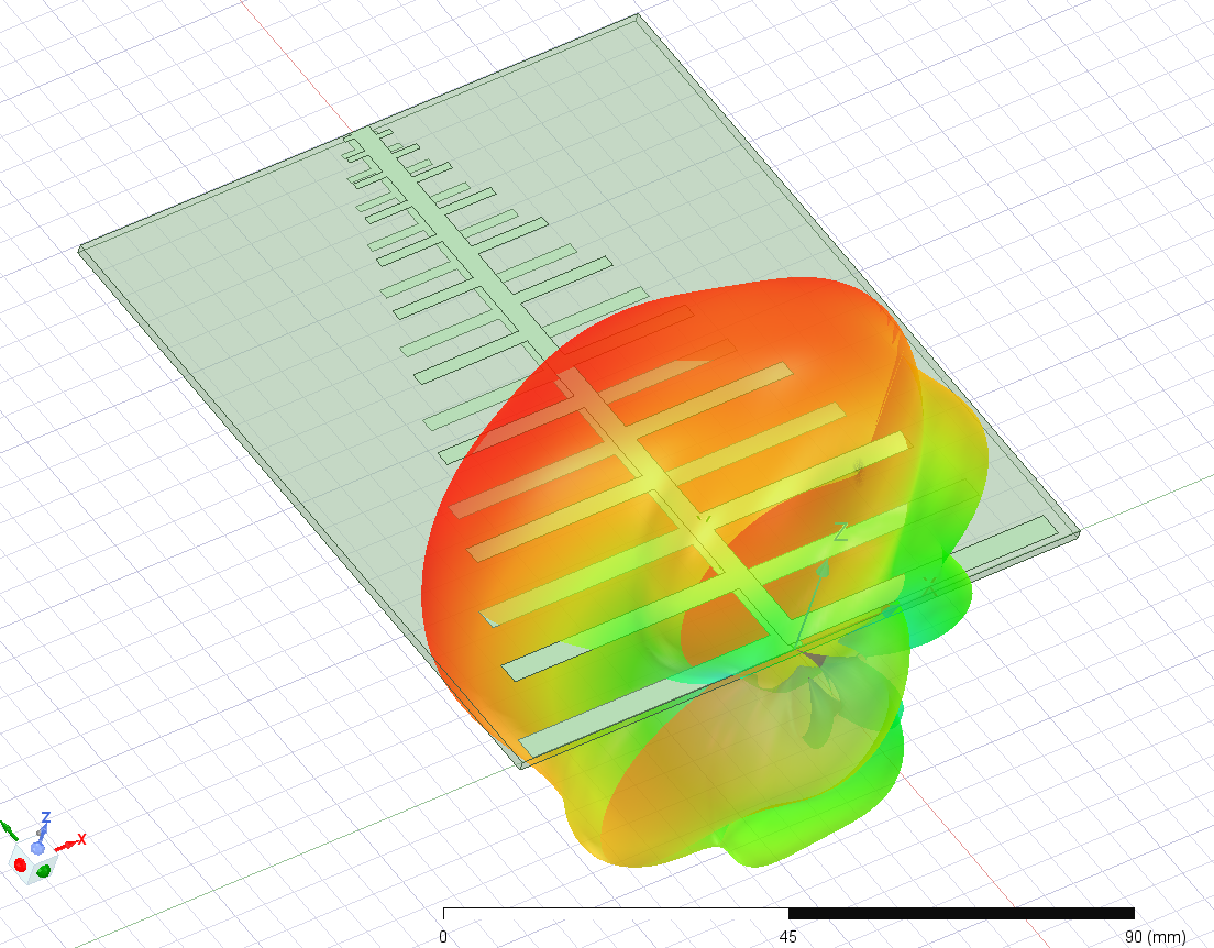
This is a log-periodic antenna operating at frequencies between approximately 1.3 GHz and 12 GHz, with a gain of around 5 dB. It has been tested with a VNA and performs well (high-frequency performance is affected by the feed line; performance above 8 GHz is not guaranteed). The board thickness is 1.6 mm; other thicknesses will affect performance, requiring the feed line to be soldered onto the front tip manually.


LPDA-handle.x_t
LPDA-handle.STL
PDF_Log-periodic antenna, operating frequency above 1300MHz, with included handle model file.zip
Altium log-periodic antenna, operating frequency above 1300MHz, includes handle model file.zip
PADS Log-Periodic Antenna, operating frequency above 1300MHz, includes handle model file.zip
94028
star night light
A starry night light made using the open-source Starry Sky PCB.
1. This is based on the Starry Sky PCB design by the Bilibili user "I'm Not Surnamed Cui," whose open-source link is: https://oshwhub.com/sytnocui/star-pcb-drawing
2. This project mainly uses a radar detection module and a WS2812B LED strip. The radar module is optional.
3. Since a 3D model was drawn beforehand, the top switch part was manually cut out. If there are many requirements, I might consider drawing a model with openings. Of course, the user can directly create their own. The back cover has no extra design; it's just glued with 502 glue. The SolidWorks source files are provided.
4. JLCPCB was used for both the PCB file and 3D printing. The PCB was free, and the 3D printing cost a total of 21.22 yuan.
6. Bilibili video link: https://www.bilibili.com/video/BV1pZ421B7Lt/?share_source=copy_web&vd_source=800b0cce2dee97823e91fad6181bdec5
7. 3D shell file link (with openings): Link: https://pan.baidu.com/s/1zqFVajP6gzTa473AMMs5oQ?pwd=eiaf Extraction code: eiaf
5. Finally, please feel free to contact me with any questions or unclear points. This is my first time open-sourcing, so please forgive any shortcomings.
Starry Sky Desktop Lamp.zip
PDF_Starry Night Light.zip
Altium_Starry Night Light.zip
PADS_Starry Night Light.zip
BOM_Starry Night Light.xlsx
94029
T12 soldering station (STC15W408AS)
T12 soldering station (STC15W408AS)
The T12 soldering station
is almost entirely for through-hole components, except for the crystal oscillator's matching capacitor, which is surface-mount (because I didn't think 20pF through-hole capacitors looked good).
It was originally a Kicad project, imported into LCSC EDA Professional Edition.
It works, but there are problems
!!! I'm not responsible for any issues with this open-source project!!! I also copied the circuit diagram and code from someone else
. Furthermore, this project will not be updated. (Because I made a small one with a 32-bit microcontroller, I won't be working on this larger one.)
Open-source license:
CC BY-NC-SA 3.0.
References (copied from the following places):
(Copied circuit diagram, slightly modified) https://oshwhub.com/myseil/stc15w408as-t12
(Copied heating end driver) https://oshwhub.com/createskyblue/opent12-jing-jian-ban
(Copied from code, slightly modified) https://www.mydigit.cn/forum.php?mod=viewthread&tid=132209&extra=page%3D1
Known Problem:
Temperature measurement has a bug. For example, if I set it to 300 degrees, the digital tube reading changes from 10 to 290 to 230 to 300. The 290 to 230 segment is instantaneous, dropping sharply. I don't know where the problem lies.
It's usable, I guess.
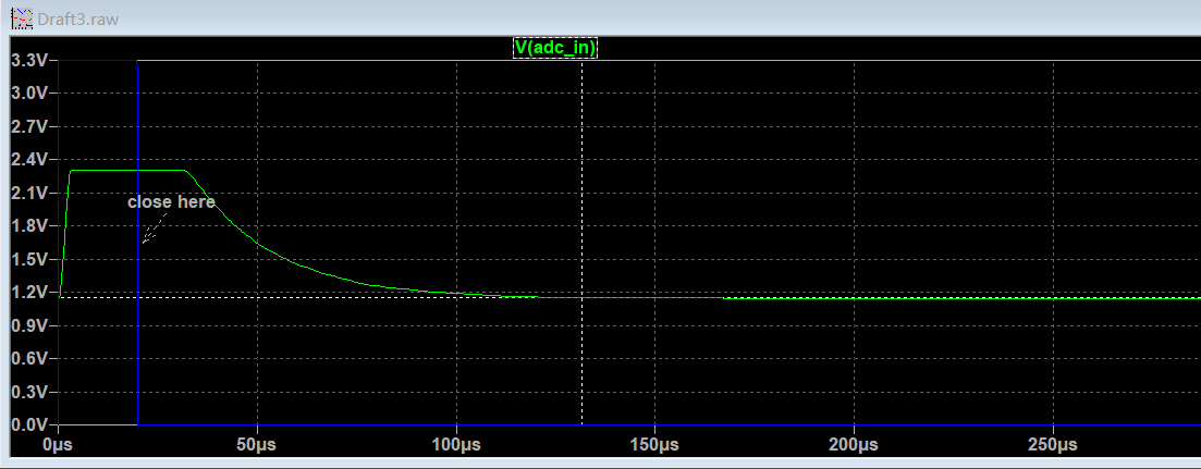
Solution: Case solved!!! Simulations showed that it takes over 100µs for the MOSFET to stabilize and the ADC value to become stable, as shown in the image. However, the code only waits for tens ofµs, so the code needs adjustment.
Increasing the delay time in the interrupt directly won't work, as it will affect the main function's refresh of the digital tube.
A feasible solution is to first shut down the MOSFET in the first interrupt after the heating time, record this in a variable, return to the main function, and then check the variable in the second interrupt to see if the MOSFET was shut down and 500µs (interrupt time) has elapsed before measuring and calculating the temperature.
Important note:
Do not connect the soldering iron during the first run. Without the soldering iron, a temperature of 500+ degrees Celsius is normal for the digital tube. Power off, connect the soldering iron, and confirm the resistance is around 8 ohms. After startup, be careful with the soldering iron and be prepared to unplug the power at any time.
1. The program download interface only has RX, TX, and GND; power is required for downloading, or connect a wire to the VCC of the STC15W408AS or add an additional VCC.
2. The external crystal oscillator is optional. If not connected, select 11.0952MHz for the internal IRC during download.
3. Zero-point drift of LM358 (there is a DT in the code to correct it) (PS: it would be better to replace it with a precision op-amp)
4. DS18B20 code not implemented
5. Vibration switch code in T12 handle not implemented
6. The pin order of the digital tube and TM1650 connection has been adjusted for wiring convenience
7. The buzzer only sounds once when the power is on, I'm too lazy to write the code... as long as it works.
8. When making the PCB, remember to specify the customer's code location. Place the JLCJLCJLCJLC in the digital tube area.
Press
once to change the set temperature to 315 degrees
. Press and hold once and release to change the set temperature to 10 degrees.
You need to
confirm whether the purchased parts match the PCB, including the size. (To be honest, I don't remember the original parts I used. I confirmed it by searching the order records on Taobao.)
1. DC-005 socket
2. KF126 3P (used to connect external power input, with the same function as the DC socket in the first item)
3. KF126 2P (used to connect the switch)
4. KCD11 switch two-pin (the opening on the PCB is 9mm*14mm), you can replace it with other switches yourself
5. DC-DC module, pay attention to the pin order and input (24V+) and output (5V) voltages
6. IRF4905 PMOS TO-220 package
7. GX12-5 aviation connector
8. LM358
9. 9042 passive buzzer (4mm lead pitch) in DIP8 package ; confirm the size yourself.
10. EC11 rotary encoder; buy a cap for a small fee.
11. STC15W408AS SKDIP28 package; note it's SKDIP, narrower than a regular DIP.
12. TM1650 DIP16. 13.
0.28-inch 4-digit common cathode LED display.
14. TL431 TO92.
15. S8050 TO92.
16. DS18B20 TO92 (I didn't write a program to drive this; you don't need to buy it).
17. Resistors, capacitors, and diodes; buy them according to the schematic (104 and 103 capacitors are CBB capacitors, lead pitch should be 5mm; 10uf electrolytic capacitors have a 2mm lead pitch and a diameter of approximately 5.0-5.5mm).
18. M3 screws, 20mm M3 copper pillars (depending on the switch height, see the picture below), 6mm building blocks (I bought 1000 blocks for 12.8 yuan, not enough, there's a hole missing on the bottom, prioritize building the sides, fill in the extra blocks at the bottom), a sheet of transparent plastic film (to block dust, just found one).

(The KF126 2P should theoretically be placed at the bottom to connect to the switch, but it looks better on top).
19. 24V 3A power supply.
20. T12 handle kit
code.
I modified the code to use SDCC. The code is messy and not organized (I just looked at it again. The program logic has clearly been changed, but there are still comments from the original code).
The code package comes with an SDCC compiler. Click build.bat to compile
the generated firmware in the bin directory. If

using the internal IRC, select 11.0952MHz frequency.
Modification suggestion:
the board is a bit exaggerated, reduce it yourself.
The original code measures the temperature every certain period of time and then uses the PID to calculate a new heating time, which is not very good. It's suggested to set the temperature measurement to: turn off the output at 50ms, measure the temperature at 51ms, calculate the PID, and output a new PWM value.
Also...
this was done a long time ago, and I don't remember it very clearly. I used it as practice when I was just starting out (so I made a large 10cm x 10cm board with all through-hole components, haha. If you understand it, you can modify it to be smaller).
Firmware download instructions can be found on Baidu.
(Maybe in two years I'll make a smaller board and reorganize the code.)
If you can't see the schematic and PCB, you can open them by clicking clone. This is a bug in LCSC's code, and they haven't fixed it for so many years.
T12code.zip
PDF_T12 Soldering Station (STC15W408AS).zip
Altium_T12 soldering station (STC15W408AS).zip
PADS_T12 soldering station (STC15W408AS).zip
BOM_T12 Soldering Station (STC15W408AS).xlsx
94032
electronic


 京公网安备 11010802033920号

 518-13-100-13-062004


