The Tuya CB3S serves as the main controller for this universal remote control, which is controlled via a WeChat mini-program. Currently, it is powered by USB 5V, but a battery circuit can be added to
the PCB body later.
A desktop charger that can help cool you down and extend battery life.
The initial inspiration:
One tiring afternoon, my phone battery was low, and the air was so stifling it felt like it was evaporating all my rationality. Desperate for a little relief, I decided to look for a fan on Taobao. But a glance at the price tags instantly dampened my spirits. The few meager bills in my wallet seemed to be silently accusing me: "Hey buddy, take it easy!"
Just as I was agonizing over whether to stay cool or go broke, those forgotten little parts in the component box under my desk suddenly whispered in my ear: "We can help you!" My inherent arrogance as an electronics student surged: "What's money? Can you eat it? I'll build this fan myself!" Just then,
OSHWhub pushed a notification for an event, as if it were destiny, and the opportunity presented itself. You see, sometimes fate is just that coincidental; when you decide not to give in to fate, it sends you a lucky card instead. So, I immediately got to work, DIYing a cool and budget-friendly super fan, giving both my wallet and my rationality a sigh of relief.
With this fan, even the hottest days have become a source of joy. I no longer need to worry about my phone running out of battery or the sweltering heat, because I'm my own boss—I can cool off whenever I want!
Requirements Analysis
: Fast Charging: Supports mainstream fast charging protocols such as USB Power Delivery (PD) and Qualcomm Quick Charge. Output power is at least 18W to ensure rapid charging of devices.
Cooling: How can we live without a fan in the sweltering summer? Adjustable wind speed, good noise control, and a cooling experience.
Temperature and Humidity Monitoring: Equipped with a high-precision temperature and humidity sensor to monitor environmental data in real time.
High-Power Power Supply: Uses an efficient power module, providing multiple voltage outputs and multiple protection mechanisms to ensure safety and stability.
Voice Control: High-precision recognition rate ensures accurate command recognition even in noisy environments.
Solution Design:
Hardware System Structure Diagram:
In this design, the hardware system includes an STM32F103C8T6 microcontroller minimum system, an SW3526 charging chip minimum system, a flyback switching power supply module, an ST7735 color screen for displaying relevant data, and an ASRPRO offline voice module.
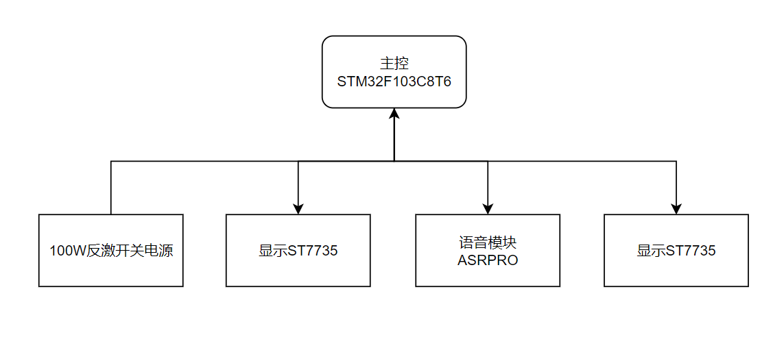
Figure 3.1 Hardware System Structure Diagram. This is the minimum
system
for the STM32F103C8T6 microcontroller. It includes a reset circuit, crystal oscillator circuit, power supply header, and other necessary peripheral circuits for microcontroller operation. All commonly used pins are brought out, making it easy for developers to embed this solution into their development. This minimum system is compatible with STM32F103C8T6, STM32F103CBT6, and other LQFP-48 packaged microcontroller chips.
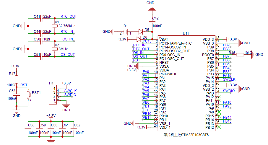
Figure 3.2 STM32F103C8T6 Minimum System Pin Assignment Diagram

Figure 3.3 STM32F103C8T6 Chip Physical Diagram
3.2.1 SW3526 Charging Circuit
The SW3526 is a highly integrated multi-fast charging protocol charging chip, supporting C-port or A-port output. It integrates a 3.5A high-efficiency synchronous buck converter, supporting multiple fast charging protocols such as PPS/PD/QC/AFC/FCP/SCP/PE/SFCP, as well as CC/CV modes. Only a few external components are needed to form a complete high-performance multi-fast charging protocol charging solution.
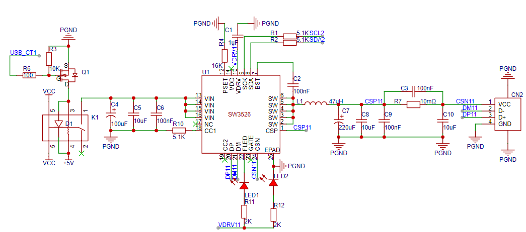
Figure 3.4 SW3526 Charging Circuit Diagram

Figure 3.5 SW3526 Charging Chip Physical Diagram
3.2.2 Differential Current Acquisition Circuit
The advantage of the differential amplifier circuit is its high common-mode rejection ratio. Common components are subtracted, leaving only the voltage difference between the two ends, which is then amplified. This is also suitable for small signal detection.
Uo=(UI2-UI1)Rf/R
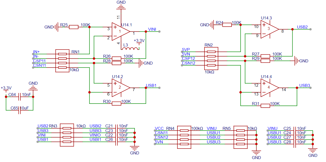
Figure 3.6 Differential Current Acquisition Circuit Diagram
Sampling Circuit Calculation Process
Here, we take STM32 and FPGA calculations as examples:
STM32 Current Sampling Calculation
The STM32's ADC is 12-bit, the reference voltage is 3.3V, the chip used is INA240A1, the sampling resistor value is 0.05Ω, and the AD sampling value is 2651. So, what is the actual current flowing through the board?
![IMG_267]()
FPGA Current Sampling Calculation
The FPGA's ADC is 10-bit, the reference voltage is 1V, the chip used is INA240A1, the sampling resistor value is 0.01Ω, and the AD sampling value is 765. So, what is the actual current flowing through the board?
![IMG_268]()
3.2.3 Atmospheric Pressure Detection Chip The
BMP280 is an absolute barometric pressure sensor designed specifically for mobile applications. The sensor module is housed in a very compact package. Its small size and low power consumption allow for implementation in battery-powered devices such as mobile phones, GPS modules, or watches. As its predecessor, the BMP180, the BMP280 is based on Bosch's proven piezoresistive pressure sensor technology, offering high accuracy and linearity, as well as long-term stability and high EMC robustness. Numerous device operation options provide maximum flexibility to optimize the device for power consumption, resolution, and filter performance. A set of tested default settings, such as use cases, is provided for developers to keep designs as simple as possible.

Figure 3.7 Atmospheric Pressure Sensor Circuit Diagram.
3.2.4 Temperature and Humidity Sensor
AHT20, a new generation of temperature and humidity sensors, sets a new standard in size and intelligence: it is embedded in a reflow-solderable dual in-line flat no-leads SMD package, 3 x 3 mm at the bottom and 1.0 mm in height. The sensor outputs a calibrated digital signal in standard I2C format.
The AHT20 features a newly designed ASIC chip, an improved MEMS semiconductor capacitive humidity sensor, and a standard on-chip temperature sensor. Its performance has been significantly improved, even exceeding the reliability levels of the previous generation sensor. This new generation of temperature and humidity sensors has been improved to ensure more stable performance in harsh environments.
Each sensor is calibrated and tested, and the product batch number is printed on the product surface. Due to improvements and miniaturization of the sensor, it offers better cost-effectiveness, and ultimately all devices will benefit from advanced energy-saving operating modes.
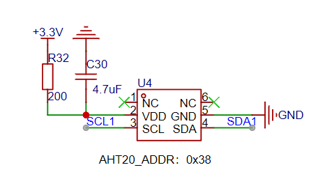
Figure 3.8 Temperature and Humidity Sensor. Figure
3.2.5 Fan Drive
Circuit. The fan drive circuit uses a MOSFET as the driver. The high level of the PWM signal controls the MOSFET's conduction time, adjusting the fan power supply. The higher the duty cycle, the faster the fan speed.
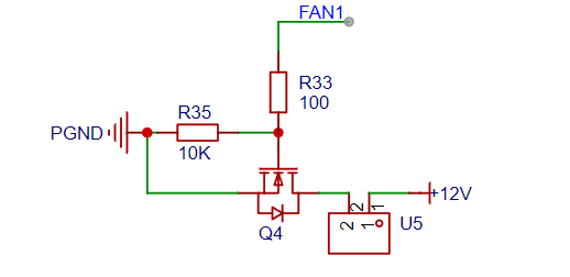
Figure 3.9 Fan Drive Circuit. Figure
3.2.5 Power Supply Circuit. The pre-amplifier
circuit includes a power-on/off circuit, but the MOSFET is not used. A reverse connection protection circuit is used to protect the circuit from reverse connection damage. A Π-type filter reduces the switching power supply ripple.

Figure 3.11 Power Supply Pre-amplifier Circuit Diagram .
The XL1509-ADJ converter converts a 24V input to 12V for fan power. The XL1509 is a high-efficiency step-down DC-DC converter with a fixed 150kHz switching frequency, providing a maximum output current of 2A. It features low ripple, excellent line regulation, and load regulation. The XL1509 incorporates a fixed-frequency oscillator and frequency compensation circuit, simplifying circuit design. The PWM control loop allows for linear adjustment of the duty cycle from 0% to 100%. It includes a built-in enable function and output overcurrent protection. When the secondary current limiting function is enabled, the switching frequency drops from 150kHz to 50kHz. The internal compensation module reduces the number of external components.
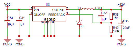
Figure 3.12
shows the XL1509 step-down circuit diagram. The LM2596-ADJ converter converts a 24V input to 5V for USB3 and voice module power. The LM2596-ADJ series regulators are monolithic integrated circuits providing all the effective functions of a buck switching regulator, capable of driving 3A loads and offering excellent line and load regulation performance. These devices are available in 3.3V, 5V, and 12V fixed output voltage versions, as well as adjustable output voltage versions. These regulators require few external components, are easy to use, and feature internal frequency compensation and a fixed-frequency oscillator. The LM2596 series operates at a switching frequency of 150kHz, allowing for smaller component sizes than lower-frequency switching regulators. A standard 5-pin TO-220 package with various lead-bending options is available.
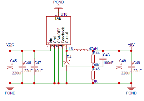
Figure 3.13 shows the LM2596-ADJ buck circuit diagram
. A 5V input is converted to 3.3V via an RT9193-3.3 for microcontroller and screen power supplies. The RT9193-3.3 is designed for the performance requirements and space considerations of wireless RF applications, featuring extremely low noise and quiescent current consumption. Even when operating in pass-through mode, its current consumption increases only slightly, effectively extending battery life. It works stably with low-ESR ceramic capacitors and has extremely low space requirements, which is crucial for handheld wireless applications. The RT9193 consumes less than 0.01μA of current in power-off mode, with a startup time of less than 50μs. It features extremely low voltage drop, high output voltage accuracy, current limiting protection, and high ripple rejection ratio, and is available in SC-70-5, SOT-23-3, SOT-23-5, WDFN-6L 2x2, and MSOP-8 packages. Figure 3.14 shows the actual appearance of
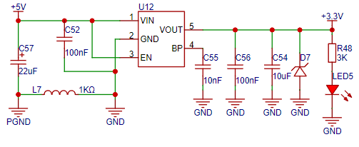
the RT9193-3.3 buck converter circuit.

Open source materials.zip
STL.zip
Desktop_Charging_Dock.zip
video.mp4
PDF_Desktop Charging Dock.zip
Altium Desktop Charging Dock.zip
PADS_Desktop Charging Dock.zip
BOM_Desktop Charging Dock.xlsx
94088
Armor plate drive plate
As an armor plate engineer, I designed a simple armor plate drive board at the request of the vision team to enable handheld armor plate adjustments. The design is rather crude, but the requirements weren't high; it just needed to work.
The task requires
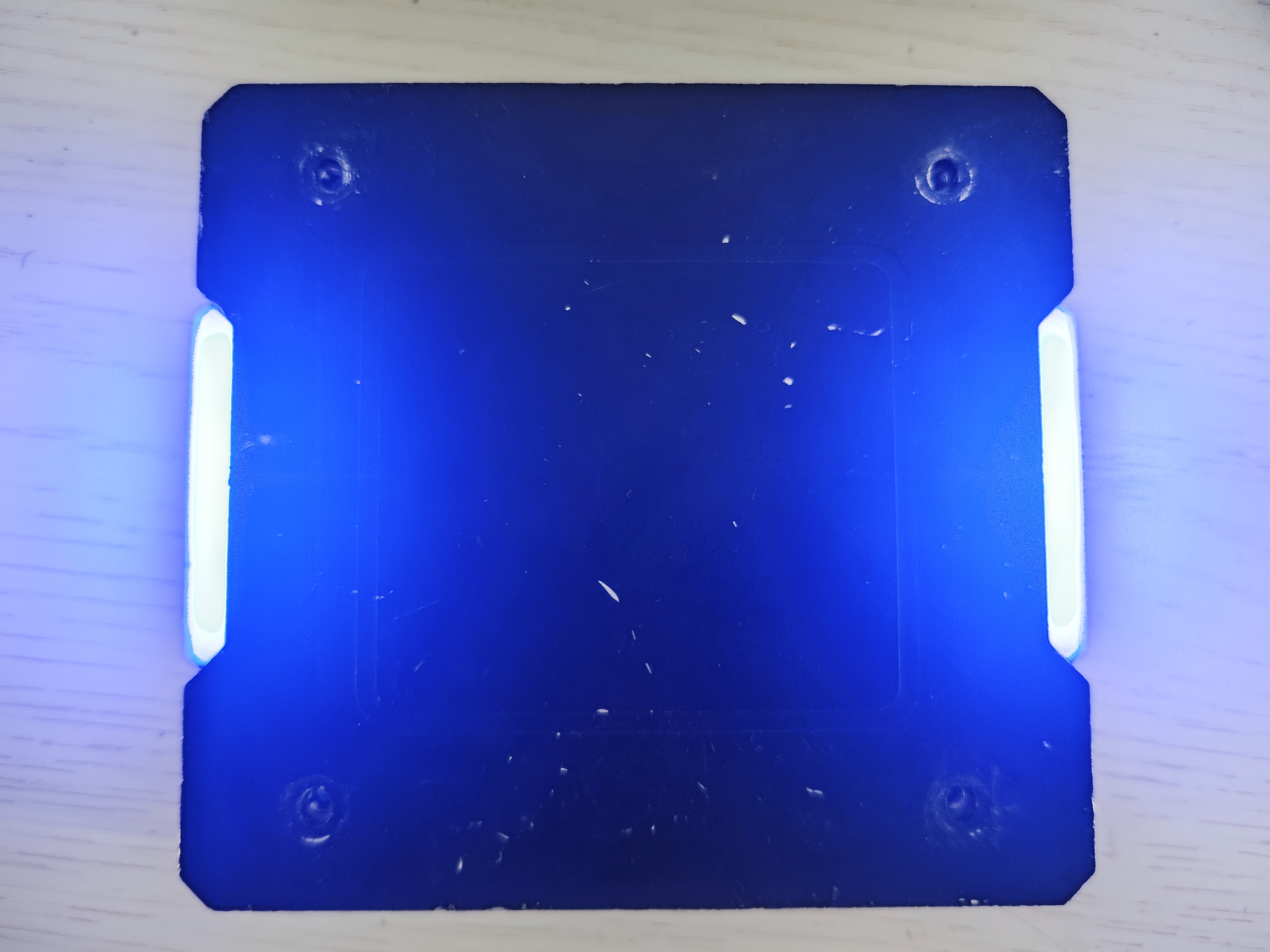
designing a light strip to drive the armor plate of the old RoboMaster referee system. The light strip should be nearly identical in brightness to the official new armor plate. It should be handheld, rechargeable, and simple to use.
The problem analysis
addresses this requirement for the vision team. It necessitates measuring the wiring sequence of the LED strip on the old official referee system. A lithium battery is needed to store power, allowing for handheld use without requiring an external power source.
The overall design scheme includes a block diagram,

schematic diagram, and design description .

The lithium battery charging circuit uses a TP4056 lithium battery charging chip, with green and red LEDs to indicate whether it is fully charged.
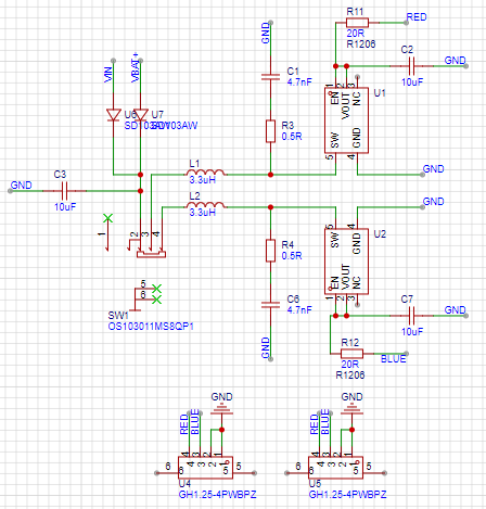
The design concept is based on the fact that only red and blue are used in the game, and these colors are mutually exclusive. Therefore, only two identical voltage regulator circuits are needed, with a switch selecting which regulator circuit to power to achieve color switching.
The circuit design controlling the armor plate brightness uses a PW5100 chip, a 5V boost voltage regulator chip for lithium batteries, capable of outputting a maximum current of 1.5A. In the diagram, SW1 is a 4-pin switch with three positions. Position 1 is used in the off state, where neither of the two voltage regulator circuits receives power and neither operates. Position 2 provides regulated output power to the red LED, and position 3 provides regulated output power to the blue LED. The two rectifier diodes U6 and U7 are to prevent 5V voltage from entering the lithium battery during charging or USB power supply, which could damage the battery.
PCB Design Notes:
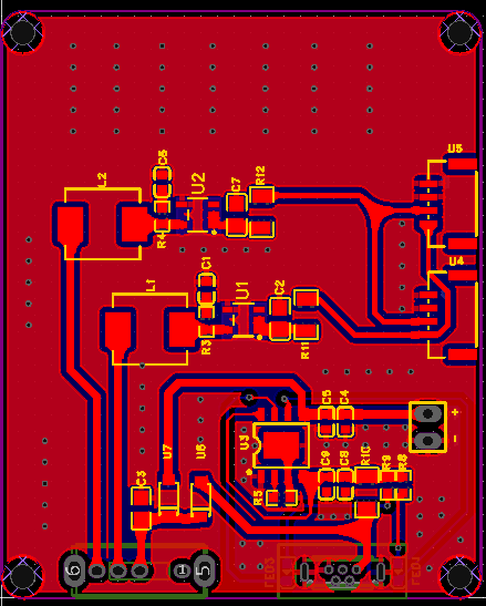
For PCB design, traces requiring current flow are recommended to have a width of 20mil or more. Special attention should be paid to R11 and R12, which are current-limiting resistors for the red and blue LEDs respectively. These need to carry current, so the packages should be changed to 1206. Most resistors will have sufficient power rating. LED brightness can be adjusted by resoldering resistors of different resistance values. In actual testing, using a 20R resistor for current limiting resulted in the LED strip's color difference closest to the official brightness.
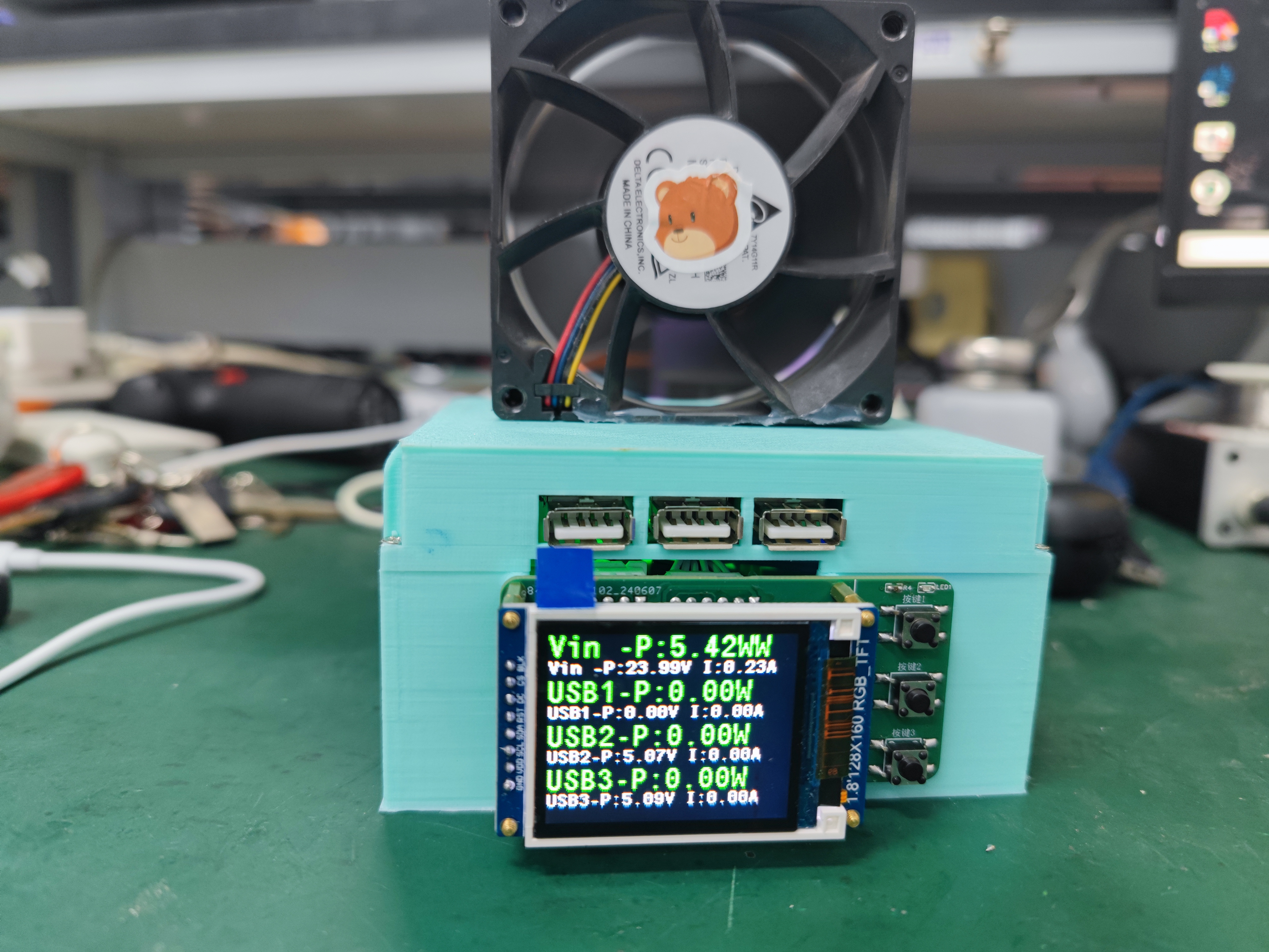
Physical Demonstration: The
PCB

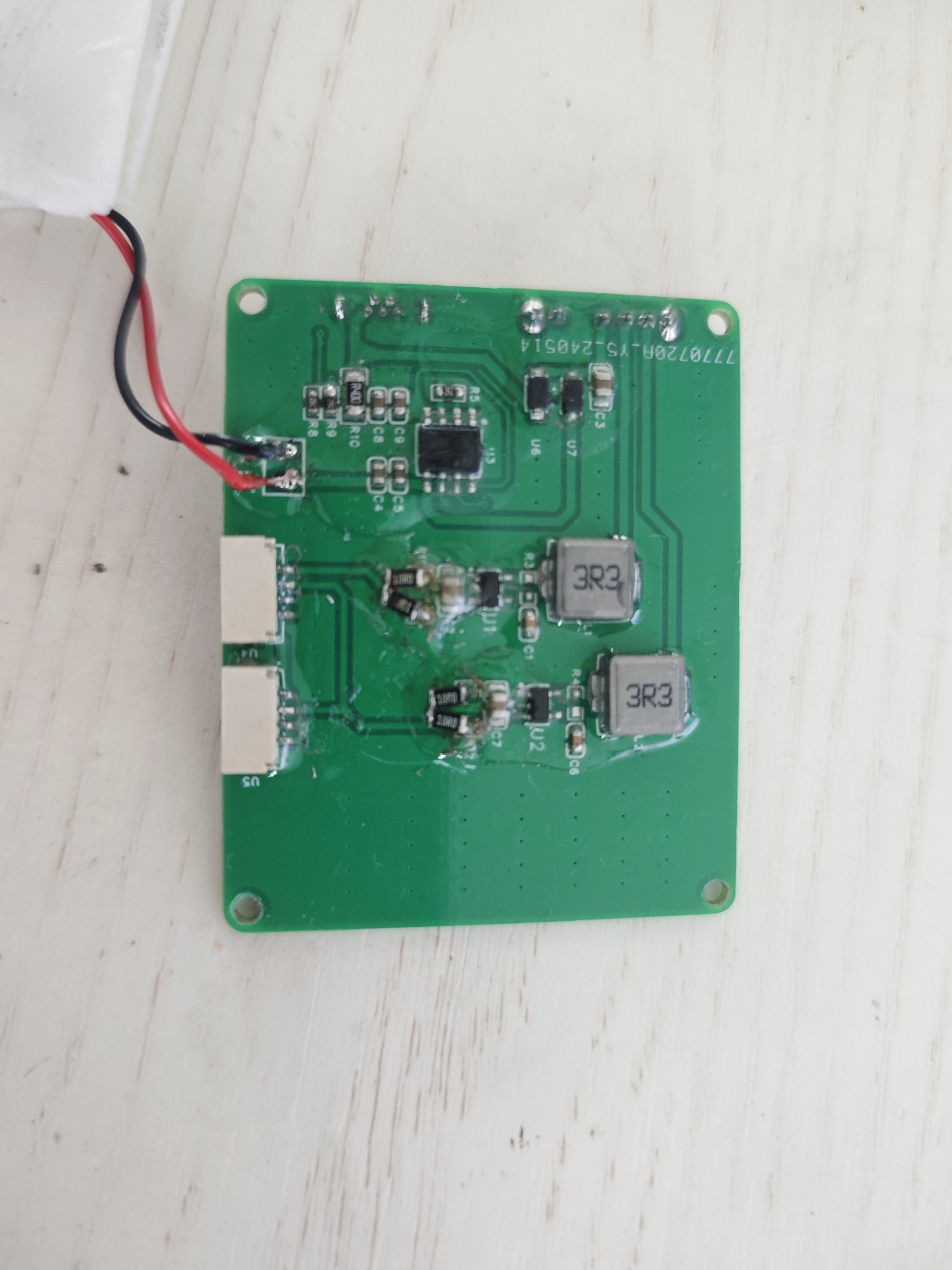
is relatively easy to solder. The smallest resistor and capacitor is only a 0603 package; simply solder them according to the schematic.
The PCB installation diagram

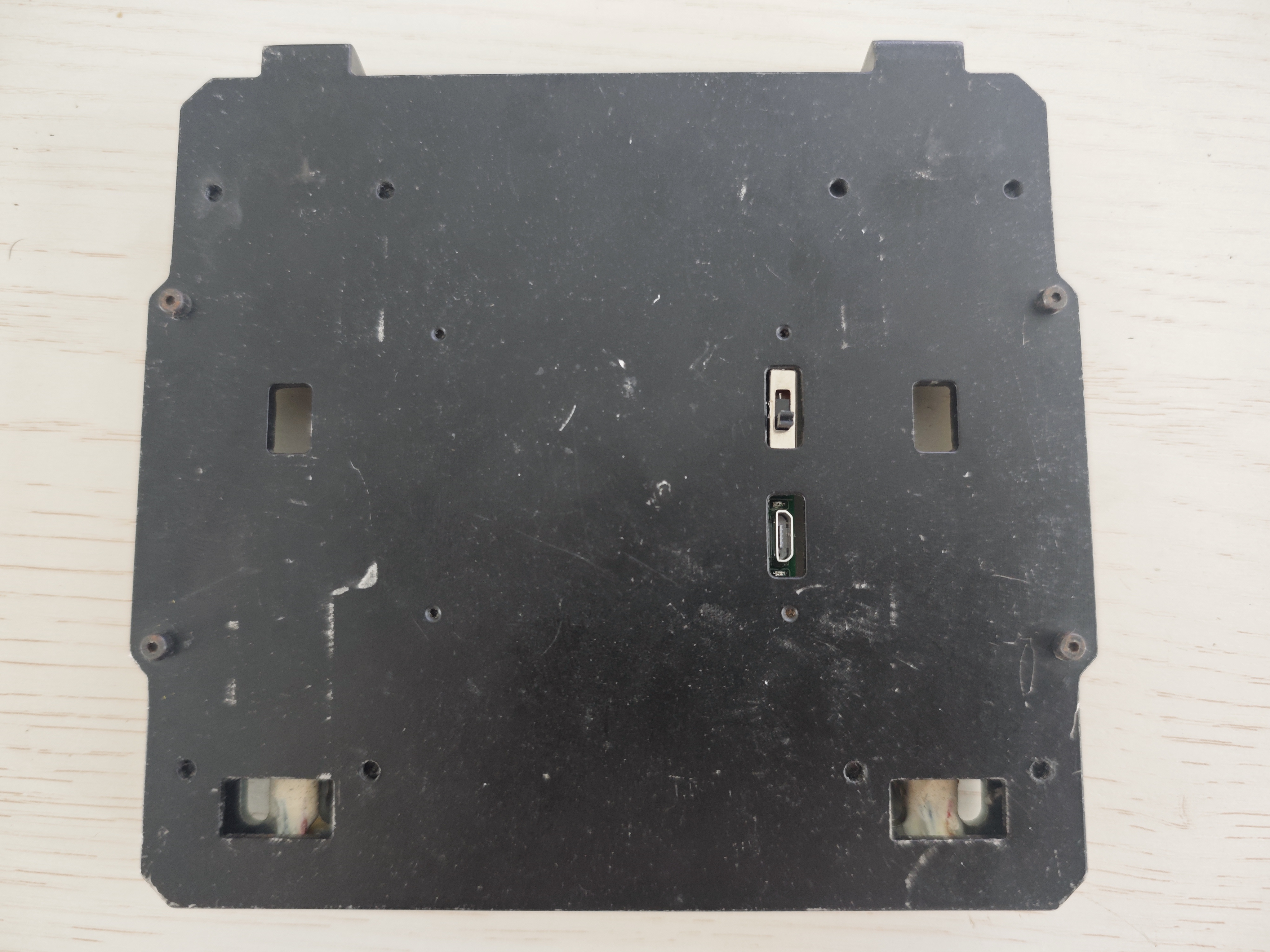
shows the same hole positions as the official original circuit board. In practice, installation simply involves removing the official PCB and replacing it with our custom-made one. Regarding wiring, just connect the two wires of the LED strip to the two GH1.25-4P connectors. Both connectors are identical, and all materials are sourced from the original mounting plate (except for the circuit board).
Important notes

:
After installation, pay attention to protecting the lithium battery and the circuit board.
A demonstration video
is attached.
VID_20240624_105324.mp4
PDF_Armor Plate Drive Board.zip
Altium Armor Plate Drive Board.zip
PADS_Armor Plate Drive Board.zip
BOM_Armor Plate Drive Board.xlsx
94089
electronic
 the PCB body later.
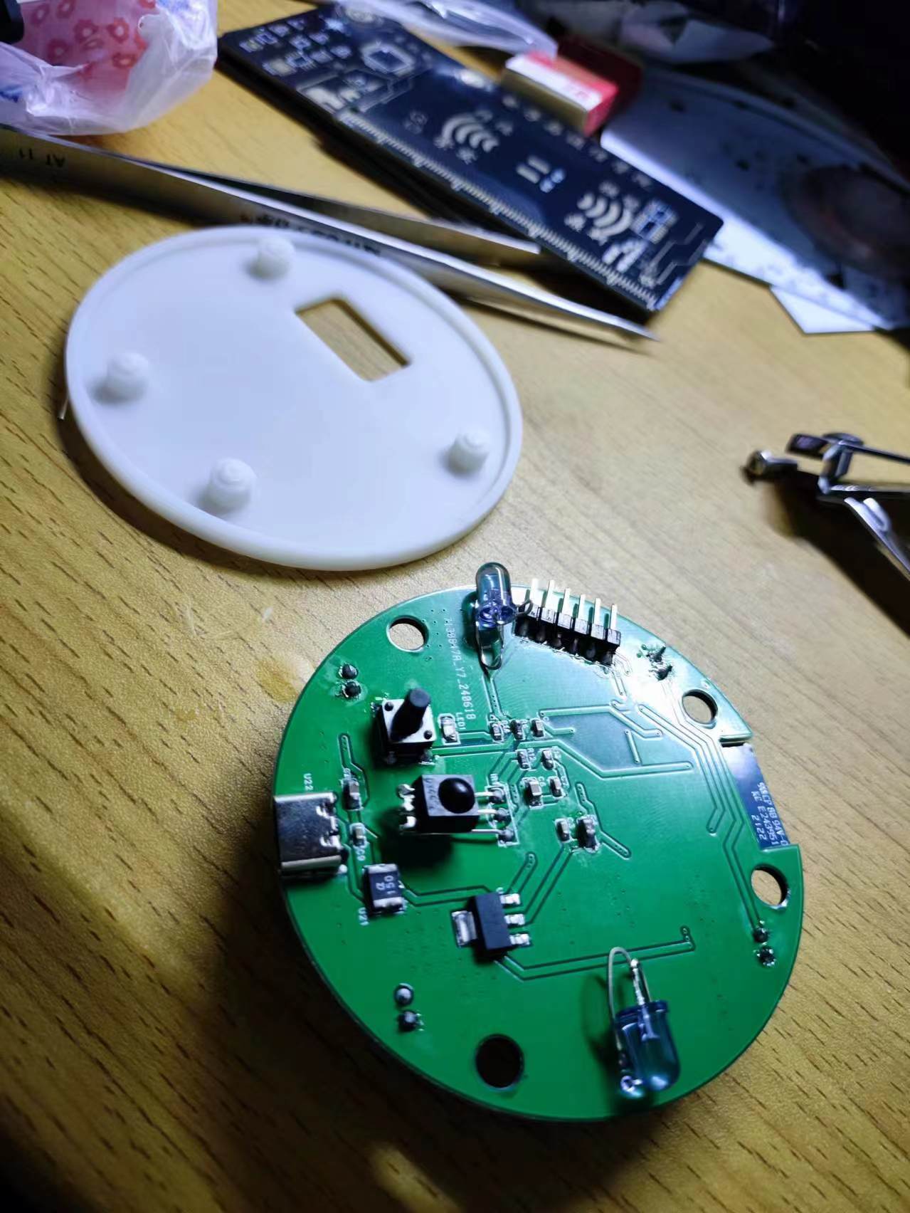


 京公网安备 11010802033920号

 MJSI-08R-11C5-18-6810


