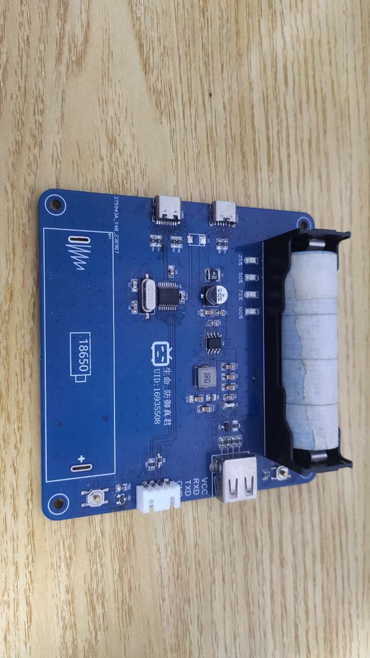
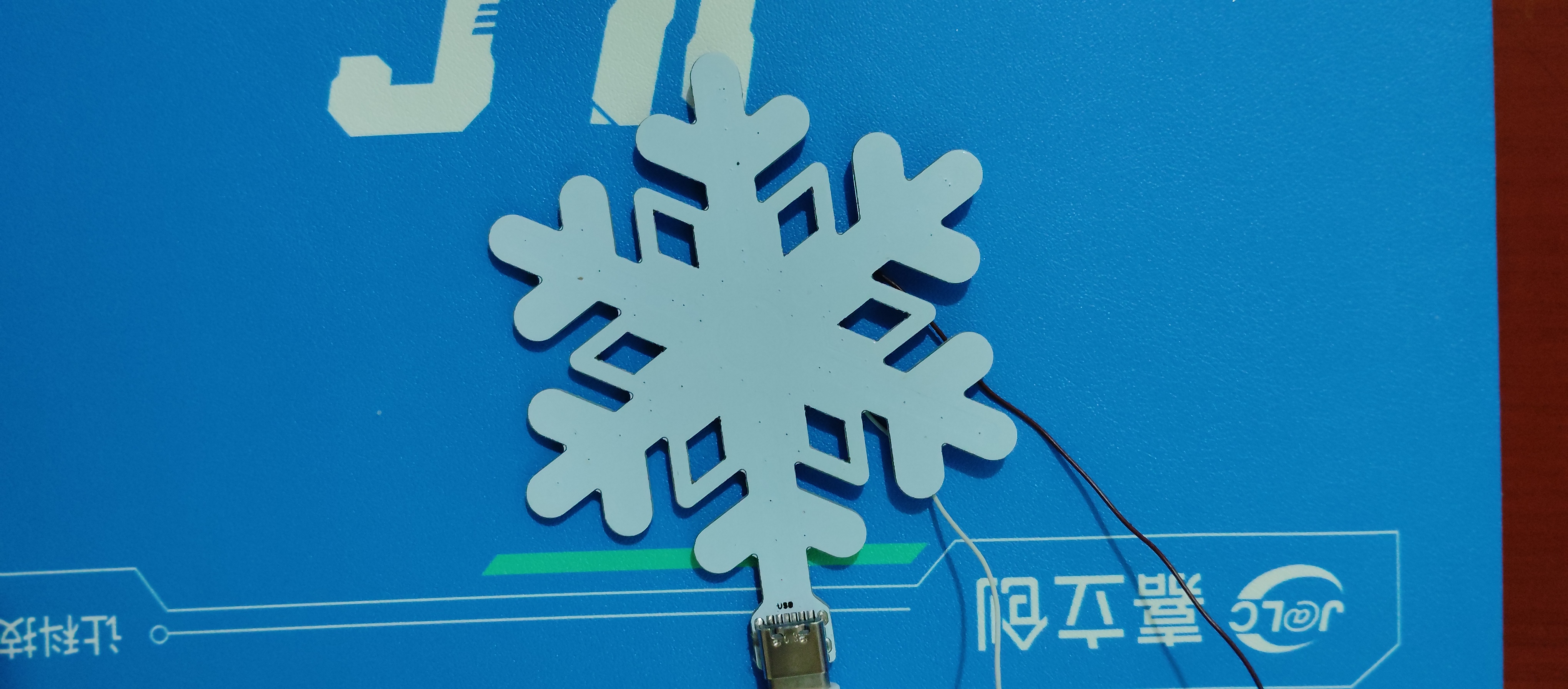
This is a dedicated programmer for serial port screens. Programming serial port screens larger than 4 inches requires an additional power supply, so a 5V power supply has been added to the original programmer.
I. Description:
I recently got my hands on a Taojingchi serial port monitor, but during use, I encountered frequent restarts and failed to program. After consulting the official documentation, I found that the USB-TTL module's power supply was insufficient, causing the screen to restart repeatedly. The inability to program was due to the CH340N chip being counterfeit, resulting in high latency and data loss. The official recommendation is to use the CP2102 or FT232 chip, or even a genuine CH340. Here,
I'm using an IP5306 to power the serial port monitor, eliminating the need for an external power supply. The serial port chip used is the CH340T.
II. Main Functions:
USB to TTL,
supports 2A output power.
When not used for programming, it can be used as a power bank.
An additional backlight circuit allows it to be used as a lighting device.
III. Important
Notes: 1. The serial port chip must be genuine. Chips sold for a few dollars on Taobao have extremely low speeds, resulting in appalling programming speeds!
2. The LED lighting section may have issues; it can be left unsoldered.
3. The resistors and diodes at the programming port do not need to be soldered; soldering is only required when programming the microcontroller.
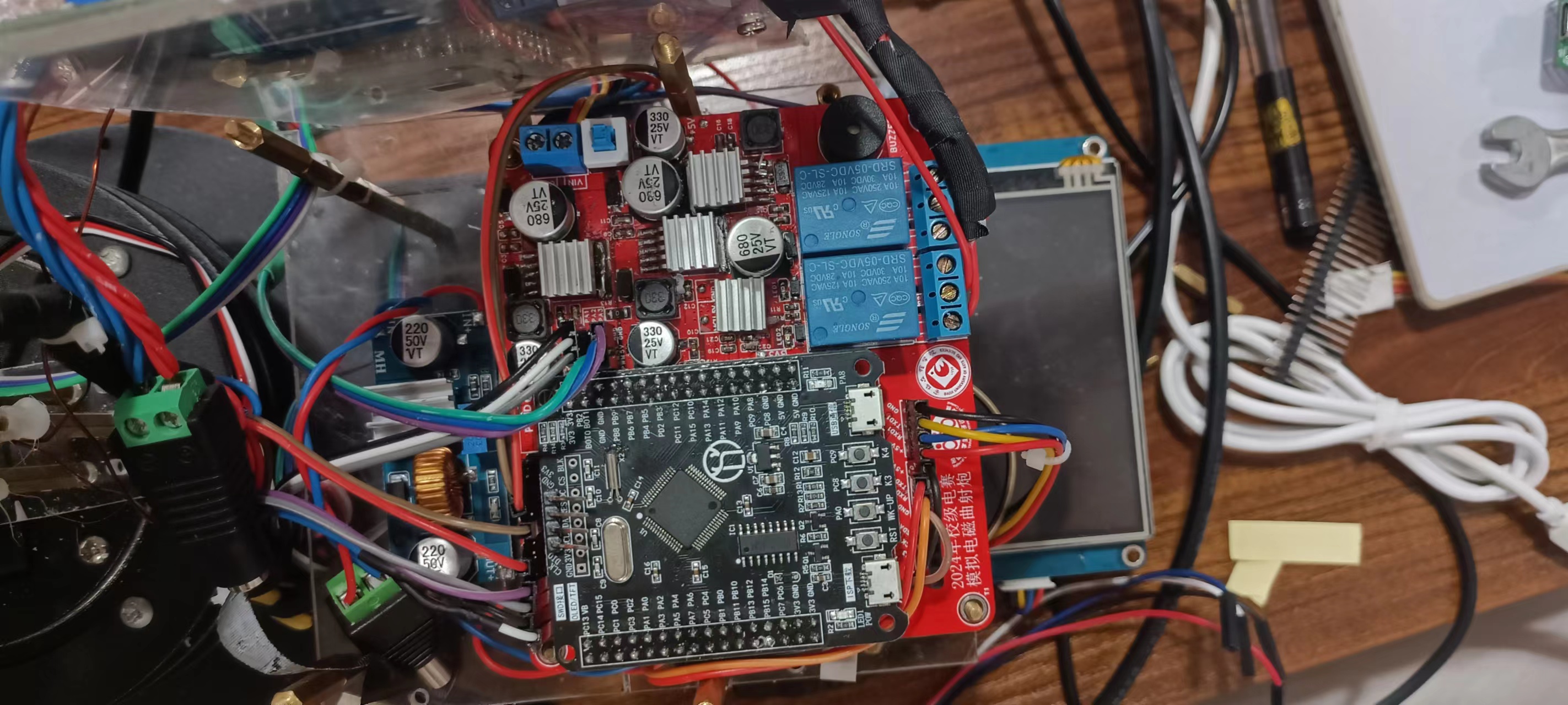
This board was designed by myself to be the main control board for the electromagnetic curved gun simulation problem in the 2019 National Electronic Design Contest. It has three onboard servo interfaces, three independent 5V power supplies, two relays, and three serial ports...
First, note that the 680uf capacitor package on this board is too small. If you're designing your own, be sure to change it!
The protection circuitry on this board uses the MechMaster A-type board protection circuit (essentially just adding capacitors, EDS diodes, and ferrite beads). After testing, it functions perfectly. So far, there have been no issues with insufficient power supply, excessive interference voltage affecting communication, or damage to components. I used this board in the school's electrical engineering competition to complete the simulated electromagnetic curved gun problem and finished the entire competition. Bottom silkscreen image source: Bilibili UP master—幾加乘
PDF_STM32F103RCT6 Extended Version.zip
Altium_STM32F103RCT6 Extended Version.zip
PADS_STM32F103RCT6 Extended Version.zip
BOM_STM32F103RCT6 Extended Version.xlsx
94123
Large-screen smart photography fill light version 2.0
This project is based on the original project, with hardware optimizations, added low-power standby, and overclocking capabilities!
This project is based on the original project, improved and optimized. For the original project, please see -> Original Project Link .
Creating this was not easy, please like, comment, and share! For the latest information, click here -> Little O Creations
. I. Update Log 2024.06.12: Based on the original project, hardware PCB was optimized. Software and hardware optimizations are as follows: 1. Fixed the issue of battery drain during shutdown; 2. Optimized BOM, reducing some components and lowering the difficulty of replication; 3. Fixed the issue of screen flickering upon startup and the issue of excessively low screen brightness; 4. Single-color temperature power increased from 3W to a maximum of 7W. The power was not fully utilized due to software limitations, considering battery and temperature; 5. Optimized button logic, fixing the issue of double-click triggering single-click; 6. Added a triple-click overclocking function;
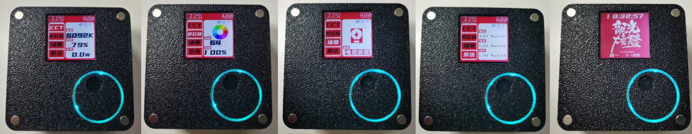
II. Function Introduction
1. UI Design

2. APP Interface Design:

3. Function Description
1). CCT Mode: Color temperature supports adjustment from 2700-13000K, brightness: 0-100%. Single-color temperature 3.25W, dual-color temperature 6.5W.
2) RGB Mode: Supports full-color RGB, HSL: 360°, brightness: 0-100%.
3) Simulated Scenes: 11 scenes: lightning, gradient color, candle, flame, police car, ambulance, high power, TV, club, flash, TV.
4) System: Viewable: maximum voltage, current, power, hardware and software version, serial number; adjustable: LED color temperature, screen off time, discharge voltage, maximum power, maximum current, overload protection.
5) Desktop network clock, automatically switches themes.
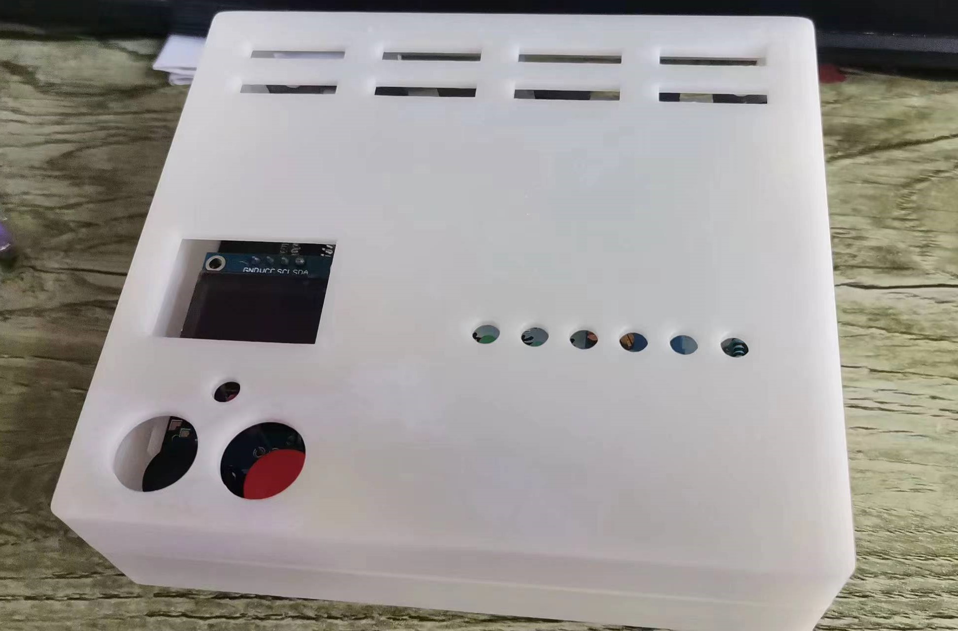
Actual product image below:
3. Boot-up guidance and network configuration
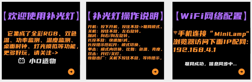
4. UI prompts

III. Soldering Precautions
1. Main Control Board
1. The EC11 knob needs to be centered, otherwise it can easily cause interference during later installation. The keycaps need to be pressed down properly, otherwise the knob may tilt unevenly.
2. Before powering on, measure whether the battery terminals BAT1 and L1 are short-circuited, then power on.
3. Components marked NC do not need to be soldered; it will not affect functionality!

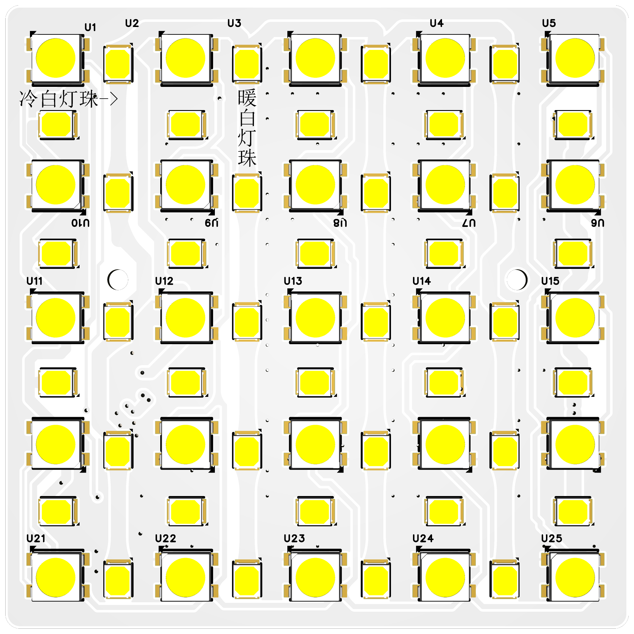
2. Lamp Board
1. Note the soldering direction of the 2835 LED beads: horizontal for cool light and vertical for warm light.
2. Note the pin direction of the 2812; the direction alternates horizontally.
IV. Hardware Introduction and Installation Please refer to the original open-source documentation .
V. User Manual and Software Burning
1. Interface Operation
1) Power On: Press and hold to release -> Offline Mode Press and hold until the prompt appears -> Network Mode.
2) Power Off: Press and hold, rotate left or right.
3) + key: Rotate right.
4) - key: Rotate left.
5) Press and hold: Quickly + or quickly -.
6) Press and hold for 1 second to release: Mode switching.
7) Single click: Switch functions within the mode, such as color temperature, brightness, and scene. 8) Double click
: Turn the light on or off; triple click for overclocking (battery voltage greater than 3.7V is required to trigger).
9) Factory Reset: Press and hold in the settings interface and wait for restart.
2. Settings Interface
1) Color Temperature Setting: Purchase different LED beads and modify the corresponding color temperature (default 2700k-13000k). - Without color temperature calibration, there may be temperature deviation.
2) Screen Off Time: Set the screen off time from 30-300 seconds.
3) Discharge Voltage: Set the minimum battery discharge voltage; the device will automatically shut down if it falls below the set value.
4) Maximum Power: Automatically shut down if the set value is exceeded.
5) Maximum Current: Automatically shut down if the set value is exceeded. (It is best to follow the battery discharge rate, for example, 2000mAh, 1C -> 2000*1/1000=2A) 6
) Overload Protection: YES: Automatically shut down if the set value is exceeded (recommended to enable); NO: Not limited by the set value.
7) Over-Temperature Protection: Automatically shut down if the temperature exceeds the set value.
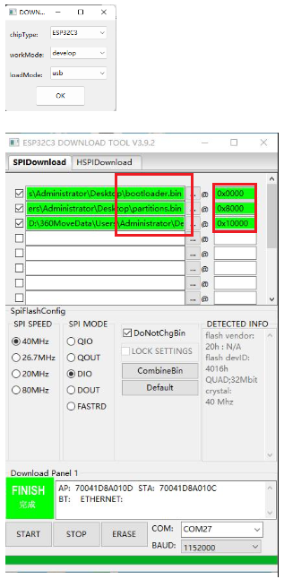
3. Software Burning
1) Software: flash_download_tool_3.9.2.exe -> Select ESP32C3 -> USB.
2) Steps: Set up as shown in the picture [you need to press and hold the knob during the burning process].
VI. APP Download and WIFI Configuration
1. Device Key (Blinker ID) Acquisition Method:
(I). Go to the official website of Lamp Technology to download the APP -> Open the APP on the official website and add the device -> Specific Method
1) Obtain Blinker ID: Open the APP -> Add Device -> Independent Device -> Network Access -> Copy the key (Blinker ID), which is needed for network configuration (you can leave it blank if you are not using the app)

2) Interface Configuration: Open the new device -> Interface Configuration -> Enter the configuration information (copy the text below) -> Update Configuration
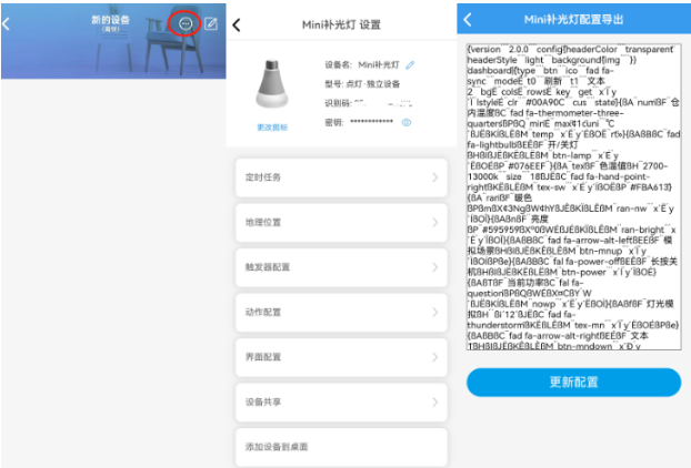
{¨version¨¨2.0.0¨¨config¨{¨headerColor¨¨transparent¨¨headerStyle¨¨light¨¨background¨{¨img¨´´}}¨dashboard¨|{¨type¨¨btn¨¨ico¨¨fad fa-sync¨¨mode¨Ë¨t0¨¨refresh¨¨t1¨¨text2¨¨bg¨Ë¨cols¨Ë¨rows¨Ë¨key¨¨get¨´x´Ï´y´Ï¨lstyle¨É¨clr¨¨#00A90C¨¨cus¨¨state¨}{ßA¨num¨ßF¨innerTemperature¨ßC¨fad fa-thermometer-three-quarters¨ßPßQ¨min¨É¨max¨¢1c¨uni¨´℃´ßJËßKÍßLËßM¨temp¨´x´Ë´y´ÉßO˨rt¨»}{ßAßBßC¨fad fa-lightbulb¨ßEÊßF¨On/OffLight¨ßHßIßJËßKËßLËßM¨btn-lamp¨´x´É´y´ËßOÉßP¨#076EEF¨}{ßA¨tex¨ßF¨ColorTemperature¨ßH¨2700-13000k¨¨size¨¨18¨ßJËßC¨fad fa-hand-point-right¨ßKËßLËßM¨tex-sw¨´x´É´y´ÍßOËßP¨#FBA613¨}{ßA¨ran¨ßF¨warm color¨ßPßmßX¢3NgßW¢hYßJÊßKÏßLÊßM¨ran-nw¨´x´Ë´y´ÍßOÎ}{ßAßnßF¨brightness¨ßP¨#595959¨ßXº0ßWÉßJÉßKÏßLÊßM¨ran-bright¨´x´Ë´y´ÎßOÎ}{ßAßBßC¨fad fa-arrow-alt-left¨ßEÉßF¨Simulate Scene¨ßHßIßJËßKÊßLÊßM¨btn-mnup¨´x´Ï´y´ÌßOÍßPße}{ßAßBßC¨fal fa-power-off¨ßEÊßF¨Long Press to Power Off¨ßHßIßJËßKËßLËßM¨btn-power¨´x´Í´y´ÏßOÉ}{ßAßTßF¨Current Power¨ßC¨fal fa-question¨ßPßQßWÉßX¤CßY´W´ßJËßKÍßLËßM¨nowp¨´x´Ë´y´ËßOÌ}{ßAßfßF¨Light Simulation¨ßH´´ßi´12´ßJËßC¨fad fa-thunderstorm¨ßKËßLÊßM¨tex-mn¨´x´Ï´y´ËßOÉßPße}{ßAßBßC¨fad fa-arrow-alt-right¨ßEÉßF¨text1¨ßHßIßJËßKÊßLÊßM¨btn-mndown¨´x´Ð´y´ÌßOÍßPße}{ßAßTßF¨battery voltage¨ßC¨fad fa-charging-station¨ßP¨#389BEE¨ßWÉßXº0ßY´V´ßJËßKËßLËßM¨num-bat¨´x´Ï´y´ÉßOÉßa»}{ßAßBßC¨fad fa-tv-retro¨ßEÉßF¨Network Clock¨ßHßIßJËßKËßLËßM¨btn-clock¨´x´É´y´ÉßPßeßOÉ}{ßA¨tim¨ßJËßKËßLËßM¨timing¨´x´É´y´Ï}{ßA¨col¨ßF¨Brightness Adjustment¨ßPß1AßJËßKÑßLÑßM¨RGBKey¨´x´É´y´ÑßOÊ}{ßAßBßCßwßEÊßF¨Overload Protection¨ ßHßIßJËßKËßLËßM¨btn-protect¨´x´Ë´y´ÏßOÊßPßQ}÷¨actions¨|¦¨cmd¨¦´b1´‡¨text¨‡´on´¨Open relay 1¨¨off¨¨Close relay 1¨—{ß1N{´b2´´on´}ß1O¨Open relay 2¨}{ß1N{´b2´ß1Q}ß1O¨Close relay 2¨}÷¨triggers¨|÷ßa|ßZß1B÷}
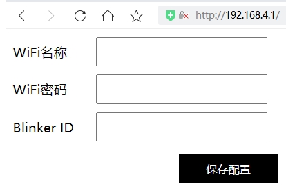
(二).WIFI network configuration:
Press and hold, release after the prompt, and enter the WIFI network configuration.
For the first network configuration, use a mobile phone or computer to connect to "MiniLamp", access the browser: 192.168.4.1, and enter the WiFi account, password, and Blinker ID (see above for how to obtain them).
VII. Replica Instructions
1. Commercial use is prohibited. Reproduction is difficult; the source code is not currently open source, only the BIN file is provided.
2. The main controller is in a QFN package. Beginners should proceed with caution as soldering errors are highly likely. Resistors and capacitors use 0603 packages.
3. The BOM list should be updated to match the actual component list. The BOM is in the attachment.
4. Attachments: Burning BIN file, 3D printing files, PCB and schematic diagram, soldering diagram.
VIII. Function Demonstration
Click here to watch the Bilibili demo video.
Remember to like, comment, and subscribe! Your support is my motivation!
[Latest] PCB Version V1.4.1 Reissue Data Package.zip
PDF_Large Screen Smart Photography Fill Light 2.0 Version.zip
Altium Large Screen Smart Photography Fill Light Version 2.0.zip
PADS Large Screen Smart Photography Fill Light Version 2.0.zip
BOM_Large Screen Smart Photography Fill Light Version 2.0.xlsx
94124
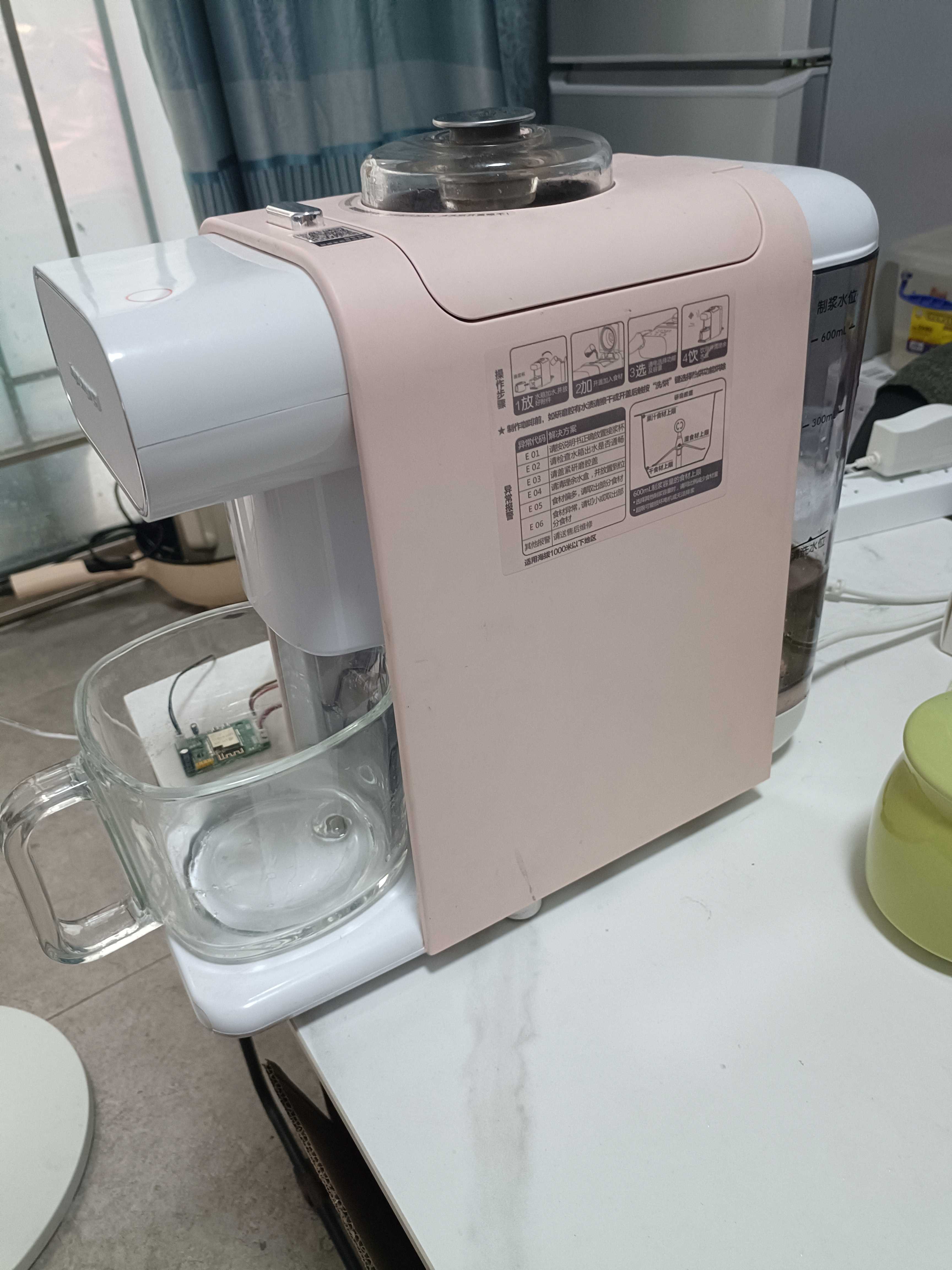
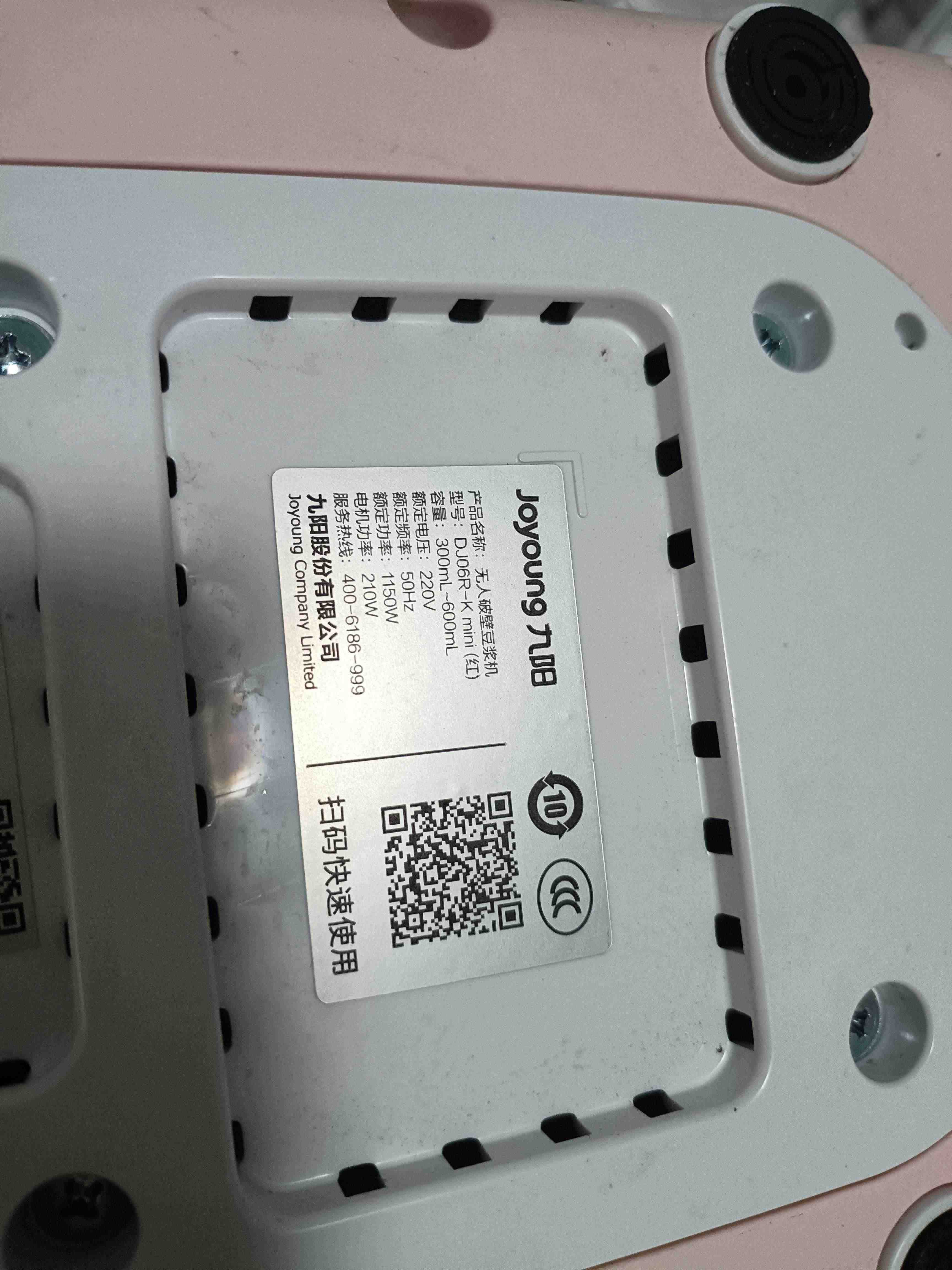
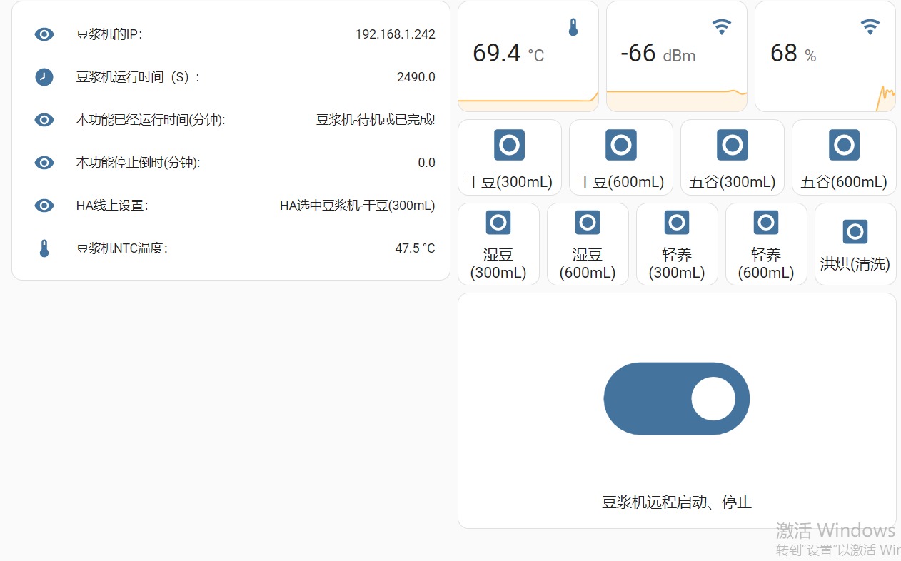
Joyoung's unmanned high-speed blender soy milk maker (automatic cleaning) can be seamlessly connected to HA (ESPHome).
Joyoung's unmanned high-speed blender soy milk maker (automatic cleaning) can be seamlessly connected to HA (ESPHome).
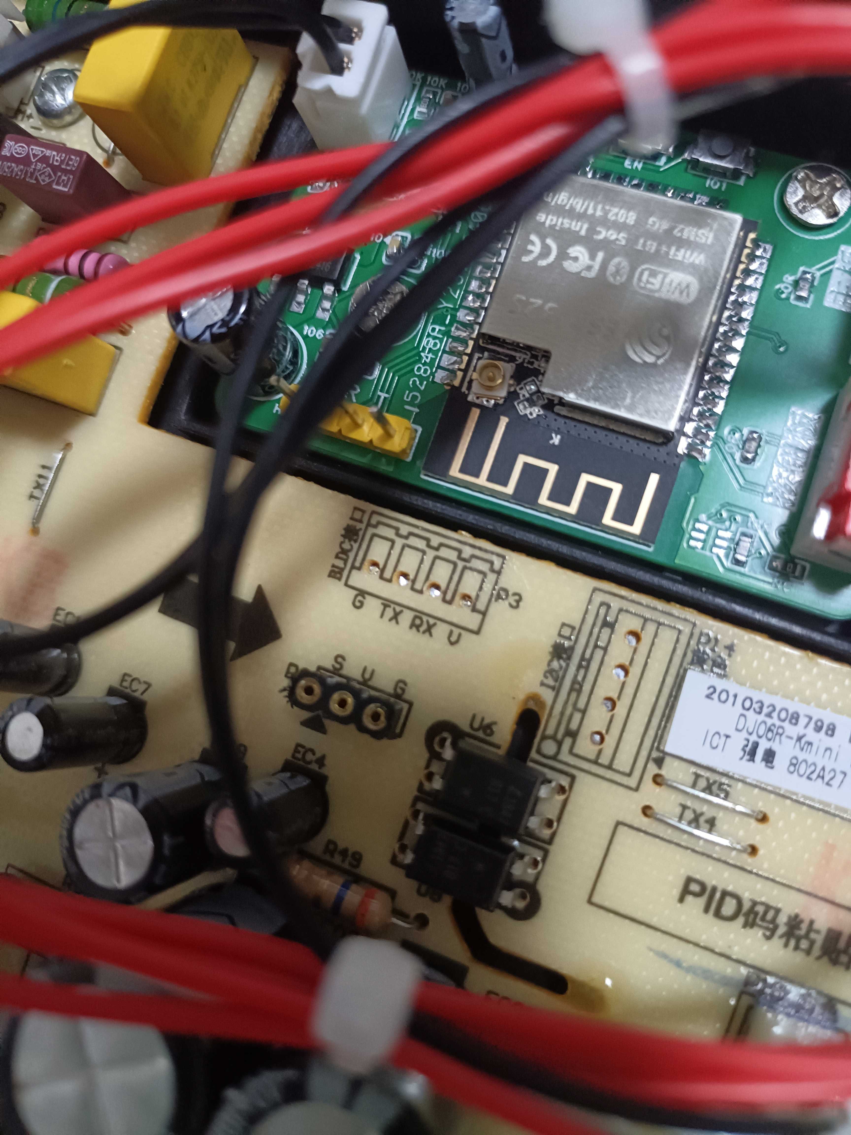
This model doesn't have Wi-Fi control (it costs around 400 RMB online, which I think is pretty awesome). I connected an ESP32 module between the LCD (control board) and the motherboard, processed the data received from the control board, and then forwarded it to the motherboard. It works almost perfectly (except for the fault alarm and timer functions, which I'll work on later). I disassembled the device countless times during the process. The software is poorly written, mostly just CTRL+C and CTRL+V. But the verification function works, right? The entire process was completed without damage, as follows: 0- System structure diagram and self-made modules:

1- Soy milk maker appearance
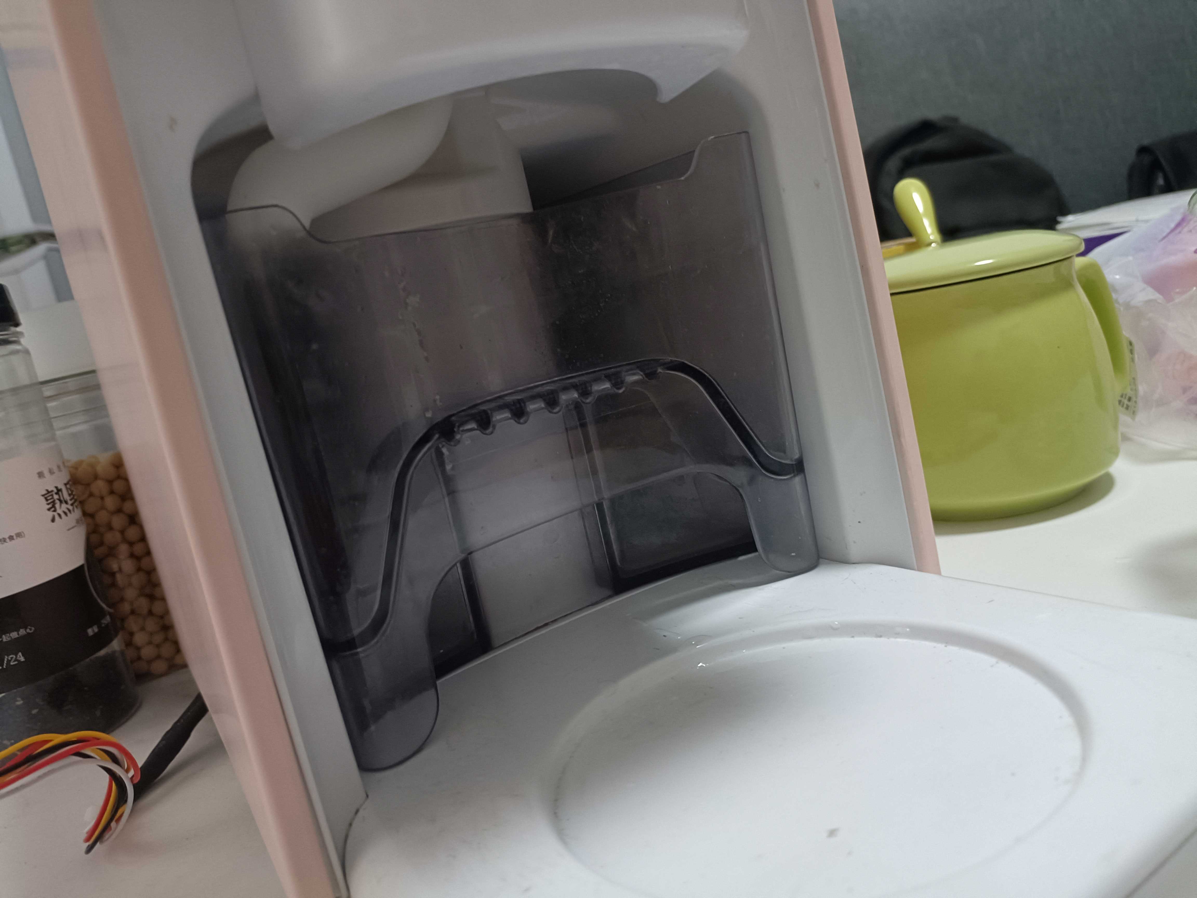
2- Soy milk and cleaning water switching port
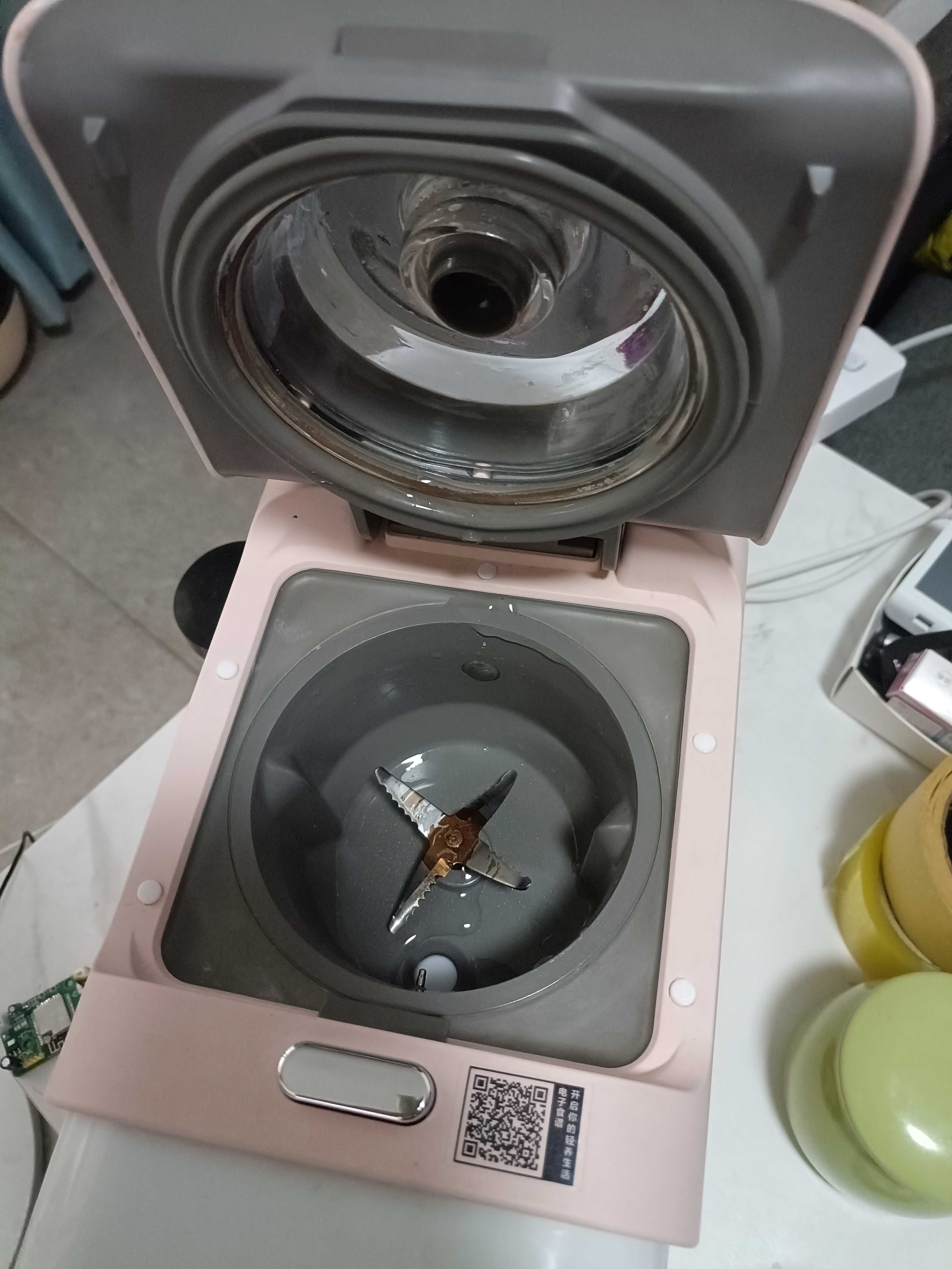
4- Soy milk working cup
5- Pure water tank
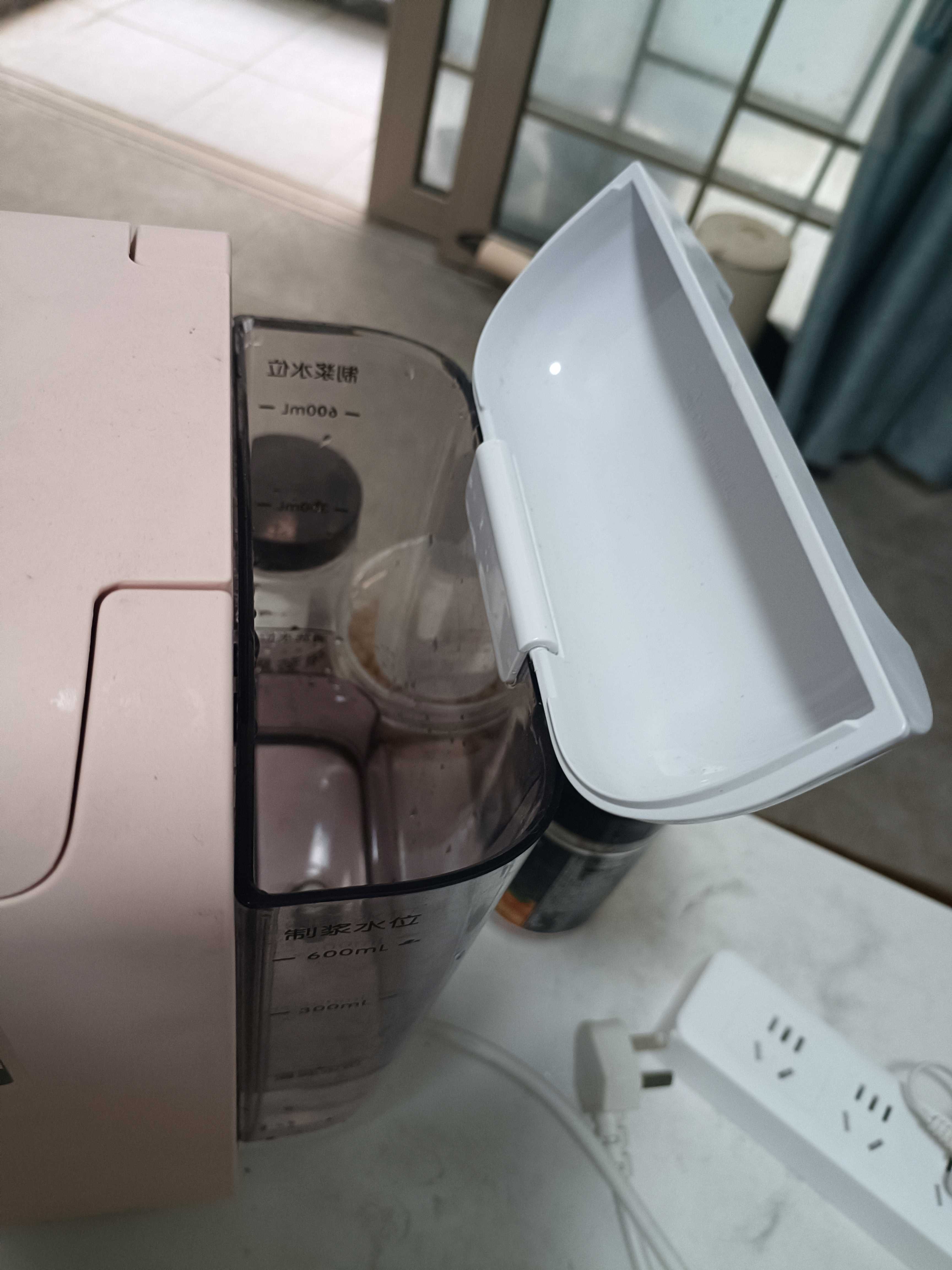
6- Soy milk cup (also has a strong magnetic sensor), 7- Cleaning water also has a sensor


8- Soy milk working cup lid is removable for easy cleaning

9A- Start removing bottom screws

12- Internal

16- Internal (two ceramic thermal fuses, one controls the main board power supply and the other controls the motor)

17- Main board
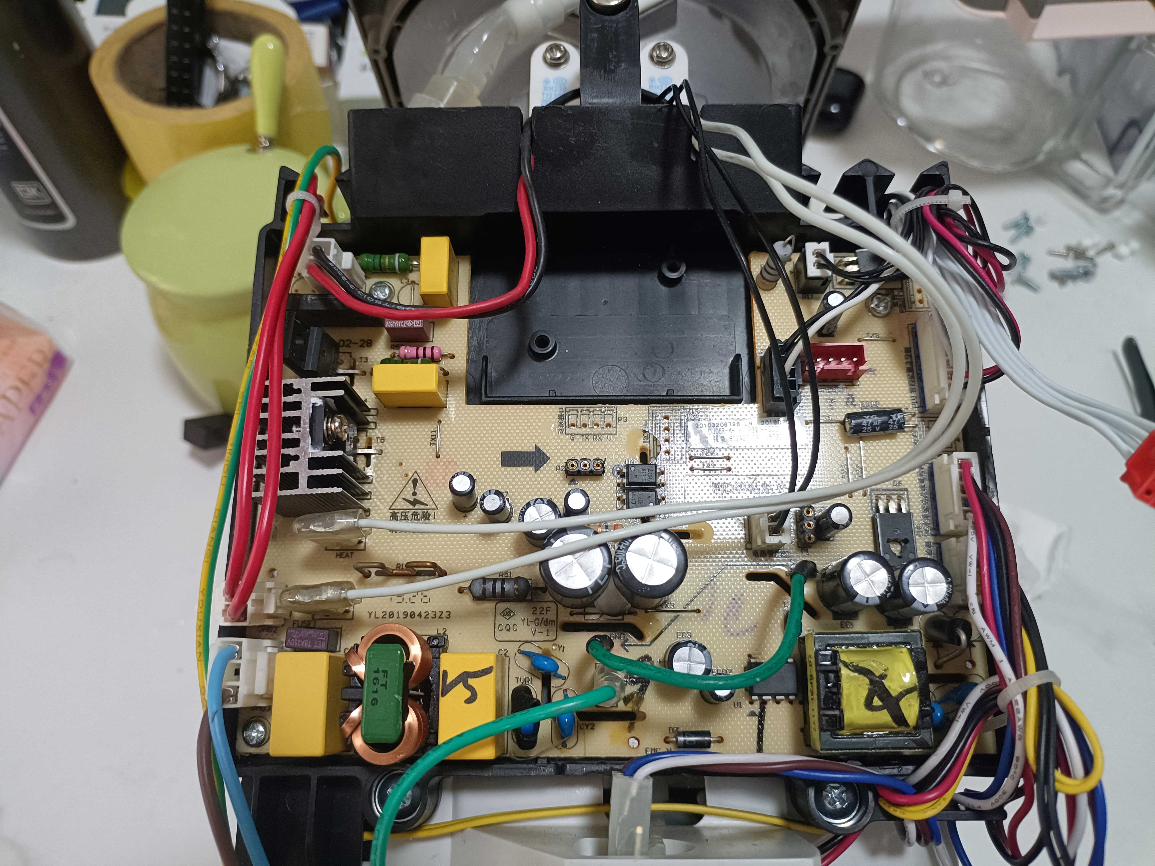
18- After installing my own modules on the main board, it looks great

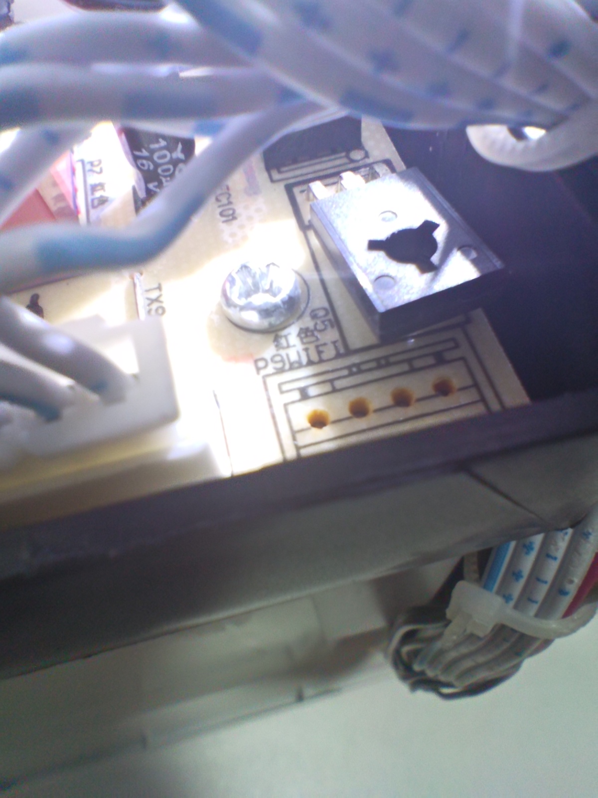
19- There is also a WIFI interface, but it may not have a communication protocol; it seems to be a serial port
20- There are other interfaces
21- Finally, the soy milk model
22- Home Assistant control panel; I'll find time to make a dedicated card for it to look even cooler
Soy milk maker (communication protocol).rar
dj06r.yaml.rar
PDF_Joyoung Unmanned High-Speed Blender Soy Milk Maker (Automatic Cleaning), with Non-destructive Connection to HA (ESPHome).zip
Altium_Joyoung Unmanned High-Speed Blender Soy Milk Maker (Automatic Cleaning), with seamless HA (ESPHome) connection.zip
PADS_Joyoung Unmanned High-Speed Blender Soy Milk Maker (Automatic Cleaning), with seamless HA (ESPHome) integration.zip
BOM_Joyoung Unmanned High-Speed Blender Soy Milk Maker (Automatic Cleaning), with seamless HA (ESPHome) connection.xlsx
94125
A modified network radio player!
Using ESP32, a seemingly simple tape recorder toy was transformed into an internet radio.
During Children's Day, a food delivery app and several fast-food chains ran a promotion where customers who spent over 61 yuan could redeem a mini radio toy.
These toys were so cute and fun, including a limited edition Snow King version, that I didn't hesitate to participate. I ended up with three radio toys that could record and play audio.
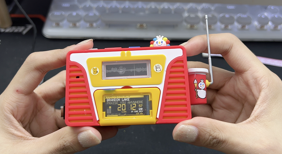
Although they could only record for 15 seconds before playing back, the casing was quite nicely made, felt good in the hand, and the colors were attractive. Plus, the radio's shape inexplicably resembled a Poké Ball radio I'd made before. So, to make the most of the casing, I decided to disassemble it and modify it into a network radio.
The firmware for this modification came from YoRadio, an open-source project by a Russian DIY enthusiast. It only required adjusting the screen resolution and driver to adapt to various hardware.
Source code download: Link: https://pan.baidu.com/s/1Bz4BZtFb9Mb8L0u38tXwhQ?pwd=pksx Extraction code: pksx -- Shared by Baidu Cloud Super Member V5.
Hardware parameters to note:
1.14-inch LCD color screen,
1 soft-pack lithium battery (model 702050)
, 1 small speaker that came with the original toy (can be replaced depending on your modifications).
Other components are standard; refer to the parameters in the project file or BOM.
Video: https://www.bilibili.com/video/BV1D4421Q7oh/
PDF_A Modified Network Radio Player! .zip
Altium - A Modified Network Radio Player! .zip
PADS - A Modified Network Radio Player! .zip
BOM_A Modified Network Radio Player! .xlsx
94126
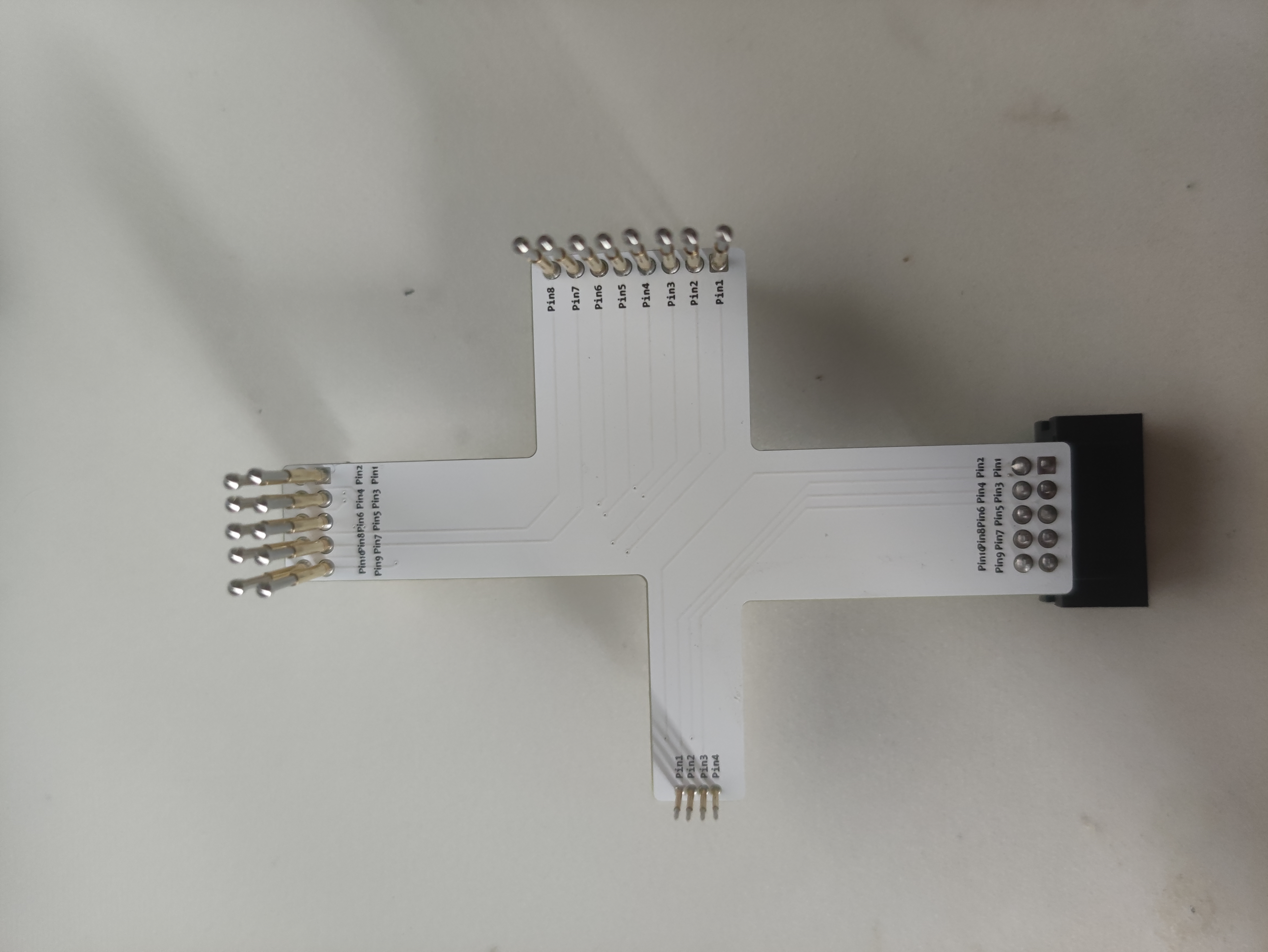
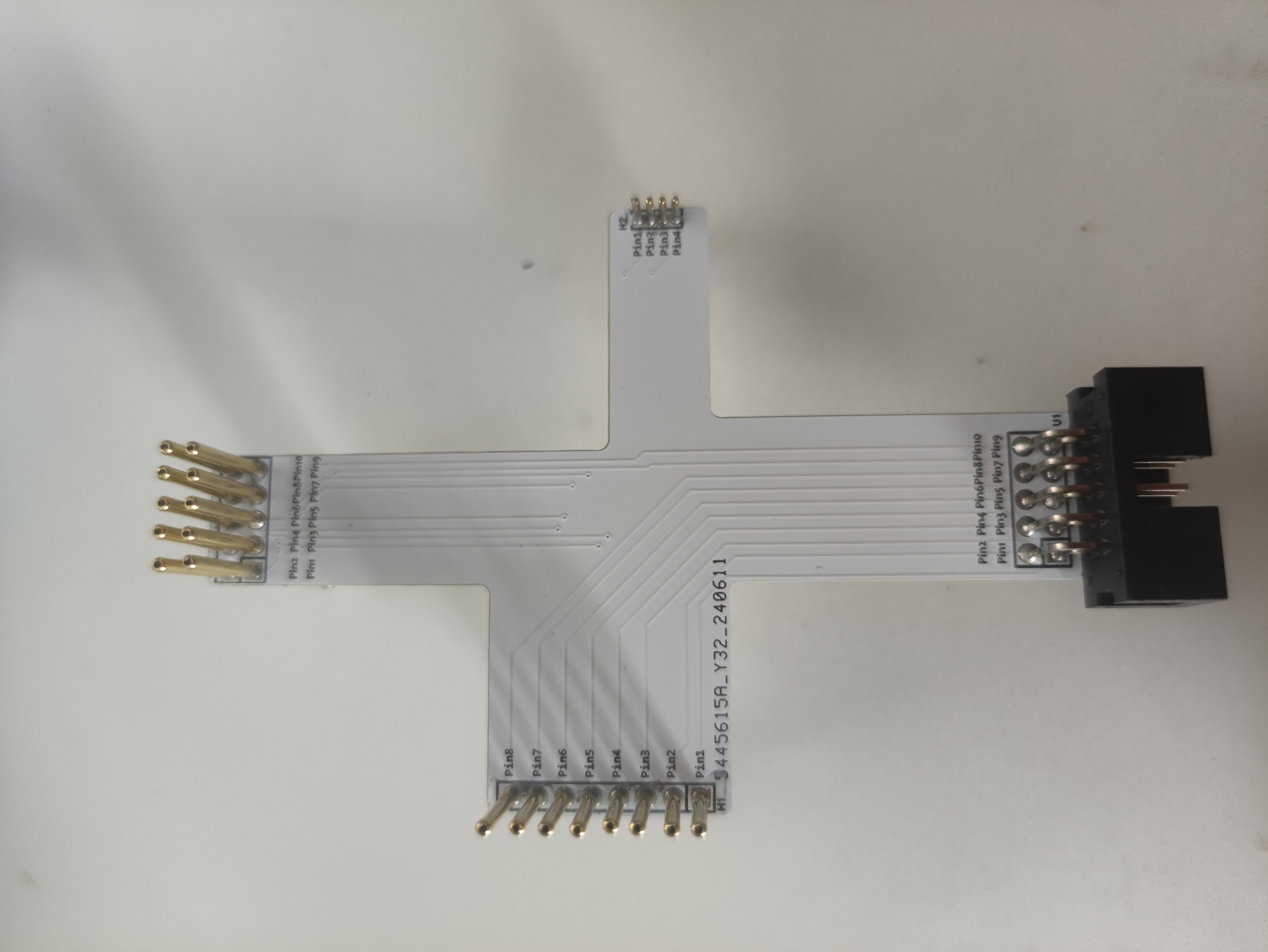
Programming probes - commonly used pitch 2.54mm and 1.27mm for 4-pin probes.
To save on pin headers and simplify the 3D casing design, I drew a probe for firmware burning. Don't ask why the PCB design is so bad; I can't even understand the circuitry.
I modified the probe hole size to perfectly fit the
10-pin probe with a 2.54mm pitch,
the 4-pin probe with a 1.27mm pitch , and the 8-pin probe with a 2.54mm
pitch .
Materials (Youxin Electronics)
total price 8.55 yuan.
Buy 2 packs of P100-E2 probes (90-degree umbrella tip), you'll need 18.
Buy 1 pack of P50-B1 probes (0# pointed tip), you'll need 4. One
DC3-10PL bent pin is needed, 5 cents each.
Finished product display.
Other instructions:
Tried it and successfully burned the Skystar GD32.
PDF_Probe for Programming - Commonly Used 2.54mm Pitch and 1.27mm Pitch for 4 Pins.zip
Altium programming probes - commonly used 2.54mm pitch and 1.27mm 4-pin pitch.zip
PADS Programming Probes - Commonly Used 2.54mm Pitch and 1.27mm Pitch for 4 Pins.zip
BOM_Probe for Programming - Commonly Used 2.54mm Pitch and 1.27mm Pitch for 4 Pins.xlsx
94127
electronic

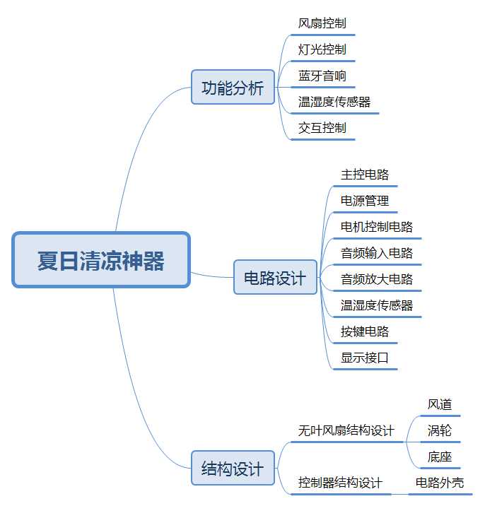 Figure 1 Design Concept
  3.1.2 Battery Management
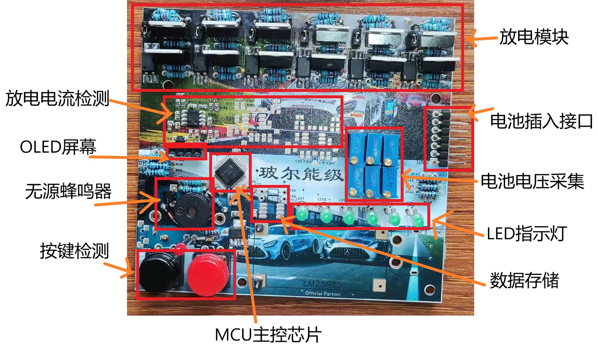
  3.1.3 Motor/Lighting Control Circuit
 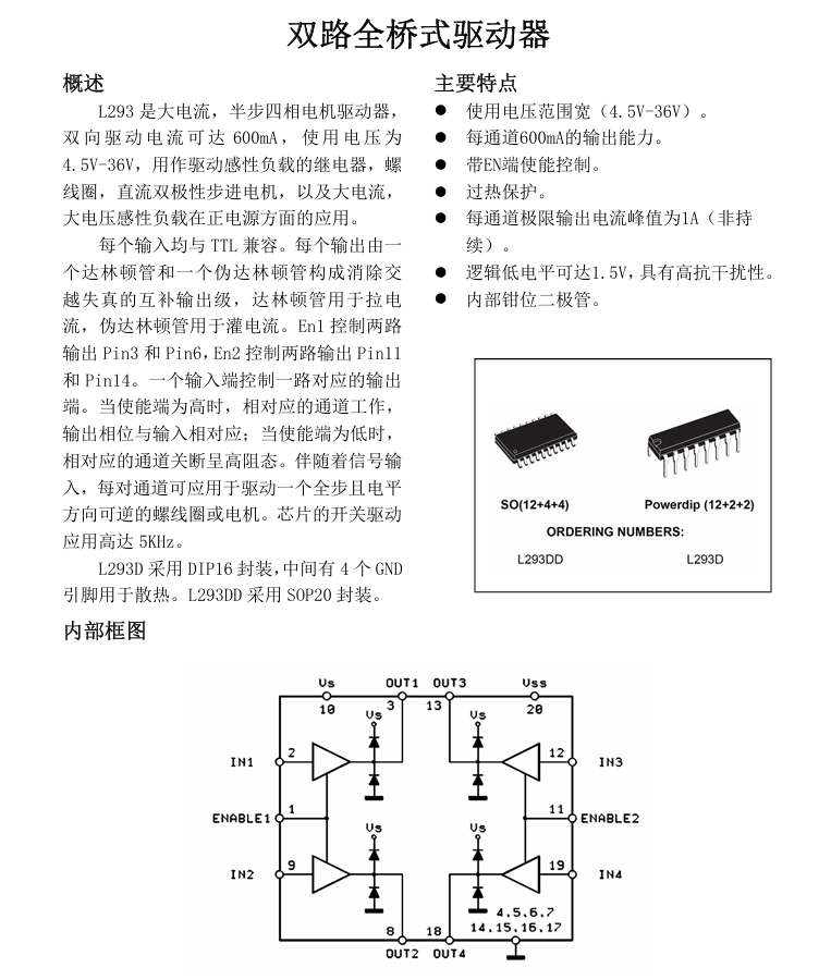 The circuit diagram can be drawn according to the manual.
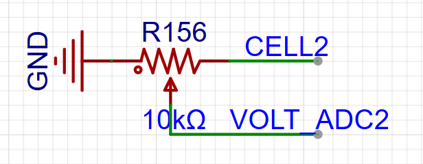
 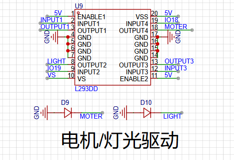 3.1.4 Audio Input and Output
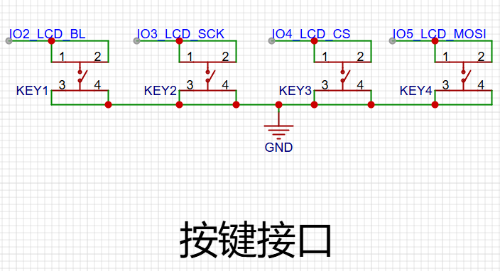
 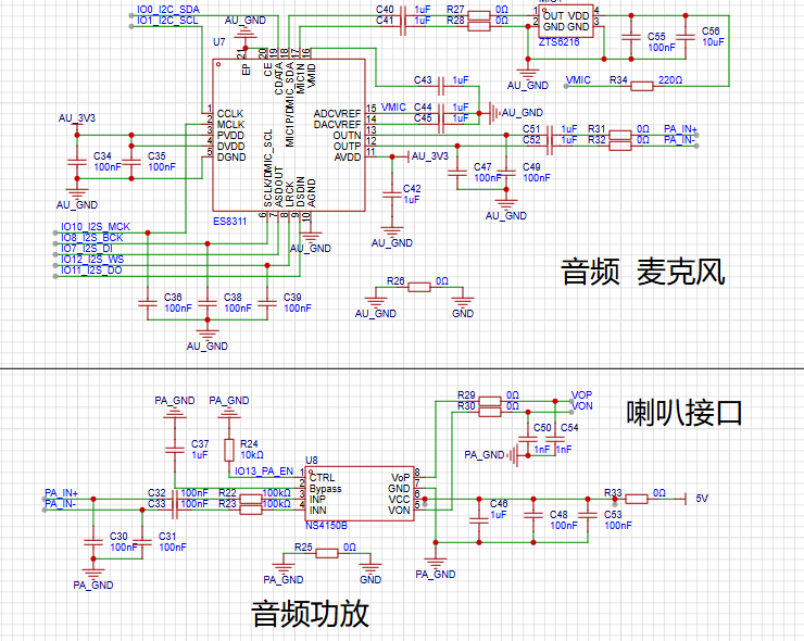 3.1.5 Temperature and Humidity Sensor, Display Interface, Button Circuit
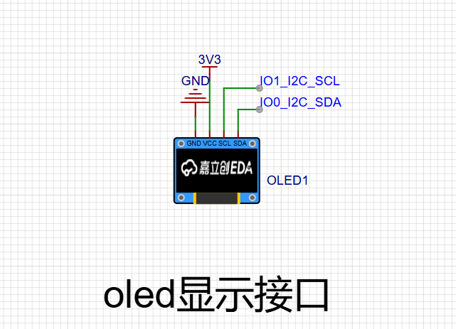

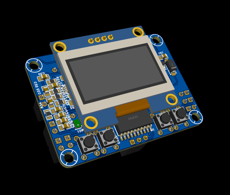
 3.1.6 PCB Design
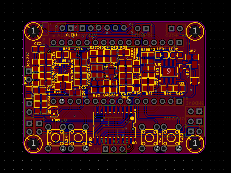
 3.2 Structural Design
 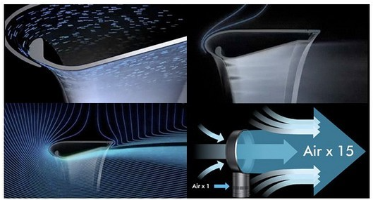 Design is carried out based on the principle reference:
 3.2.2 Controller Structure Design
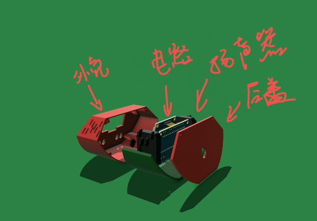

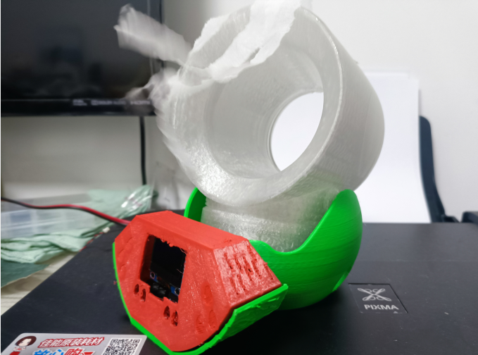
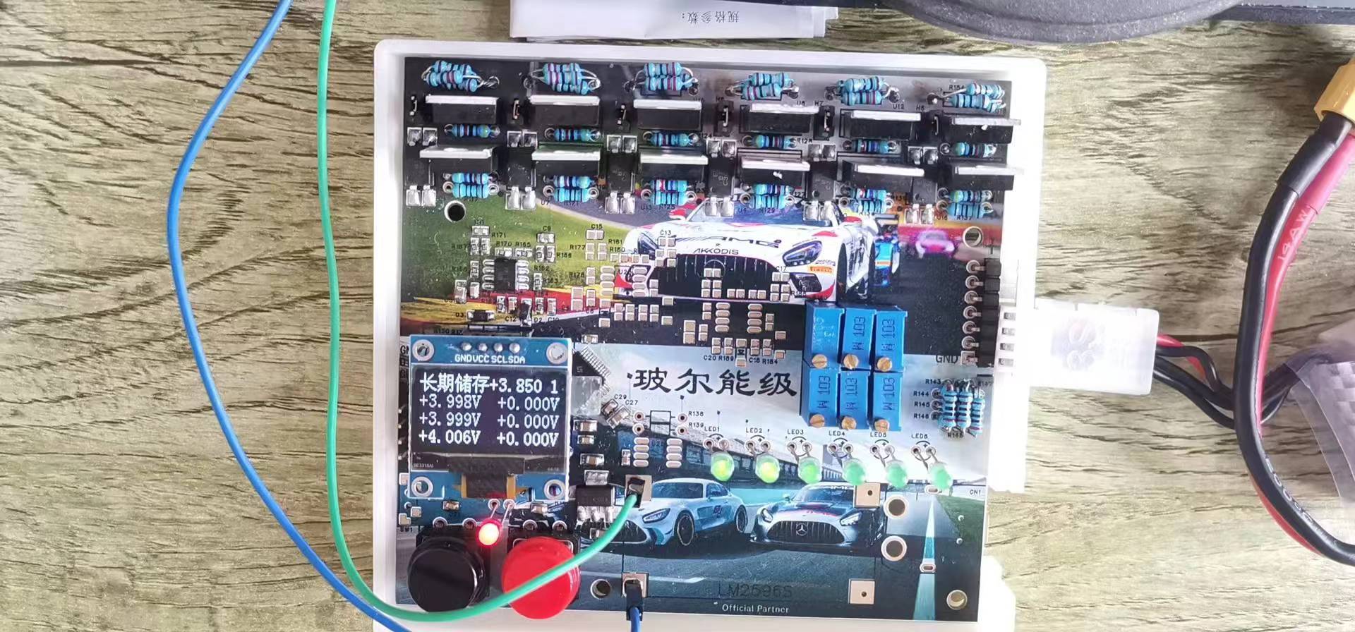
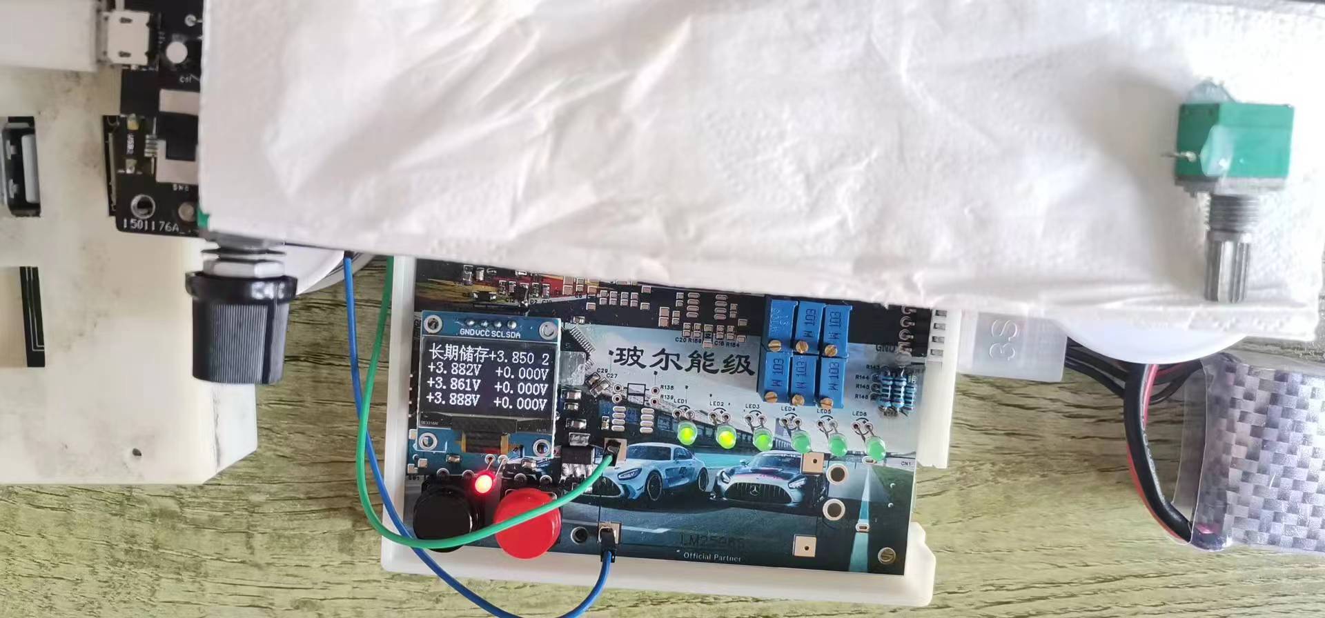
 IV. Assembly and Fabrication
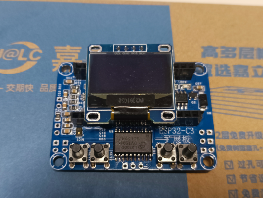
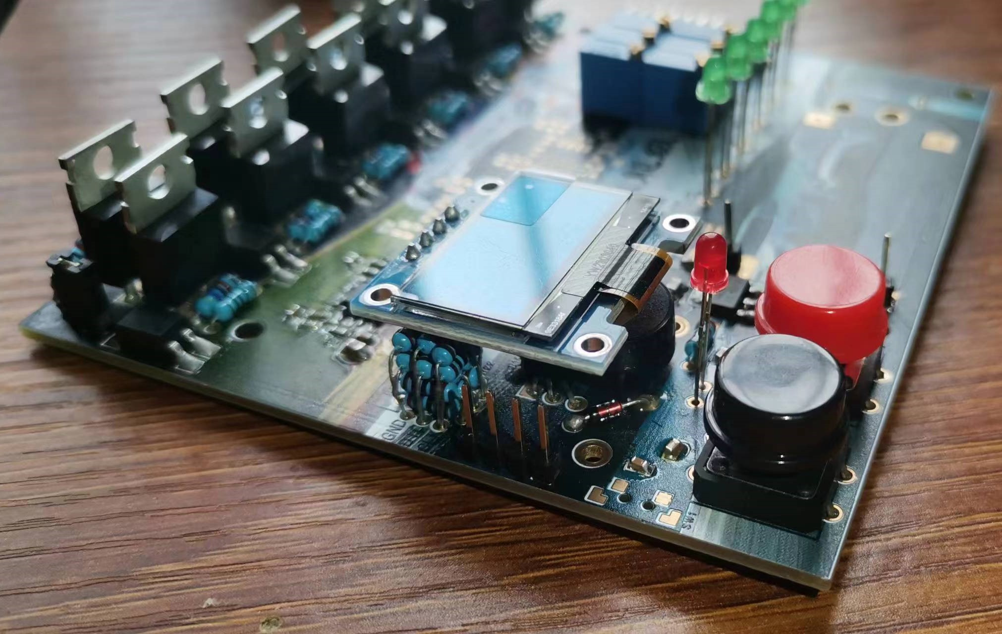


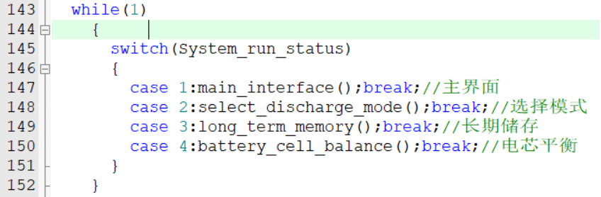


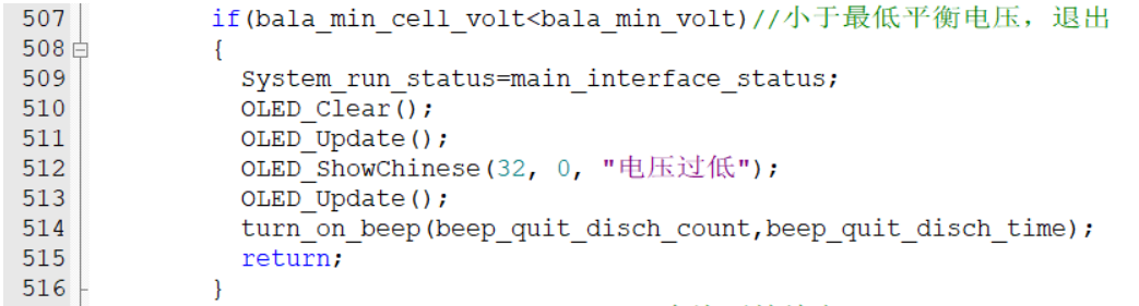


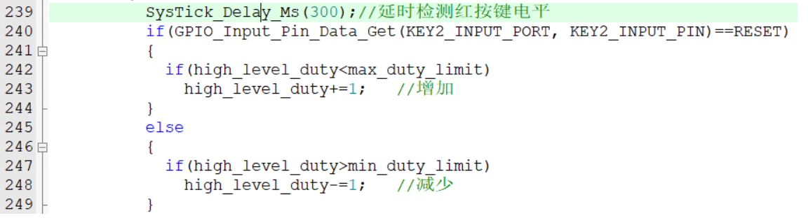 The discharge speed is adjusted using a single button, with options to increase and decrease the speed. To differentiate between these two, a long press increases the speed, and a short press decreases it. Specifically, after an interrupt is generated when the button is pressed, there's a delay of approximately 300 milliseconds, then the GPIO pin level is read. If the level is low (indicating the button is still pressed), the value of `high_level_duty` is incremented; if it's high (indicating the button is released), the value is decremented.
 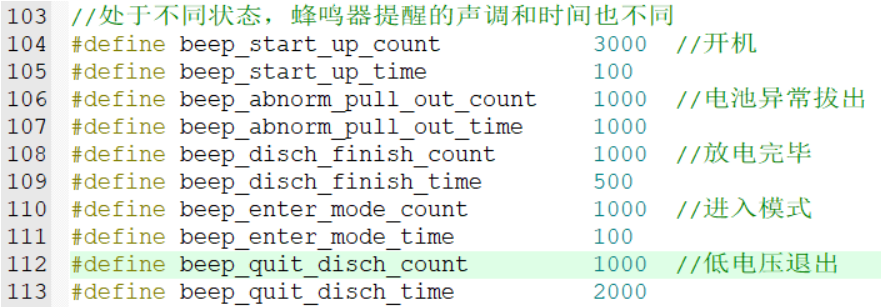 here, allowing users to adjust the tone and duration of the buzzer. This project, except for the OLED code which is ported from the author Jiangxie Technology, is entirely original in terms of algorithm and hardware design. You may use it in your personal development projects, but commercial use is strictly prohibited. The


 京公网安备 11010802033920号

 EVD50P1FZT2S


