Because the laptop fan was too small, causing the laptop to overheat, and since I had a spare case fan, I made a PWM speed-controlled
fan power supply that doesn't use a speed control circuit; it just goes through the circuit board. Therefore, the fan size it can power depends on your power supply.
This circuit uses an operational amplifier (op-amp) relaxation oscillation circuit, specifically the LM393. The generated PWM duty cycle is adjustable from 0% to 100%.
Compared to some dedicated PWM generators, this circuit is low-power and low-cost, making it an excellent choice.
3D-printed casing. (Casing link)
Designed specifically for the AIoT market, it supports 2.4 GHz Wi-Fi and Bluetooth 5 (LE), boasts powerful AI computing capabilities, and secure encryption mechanisms.
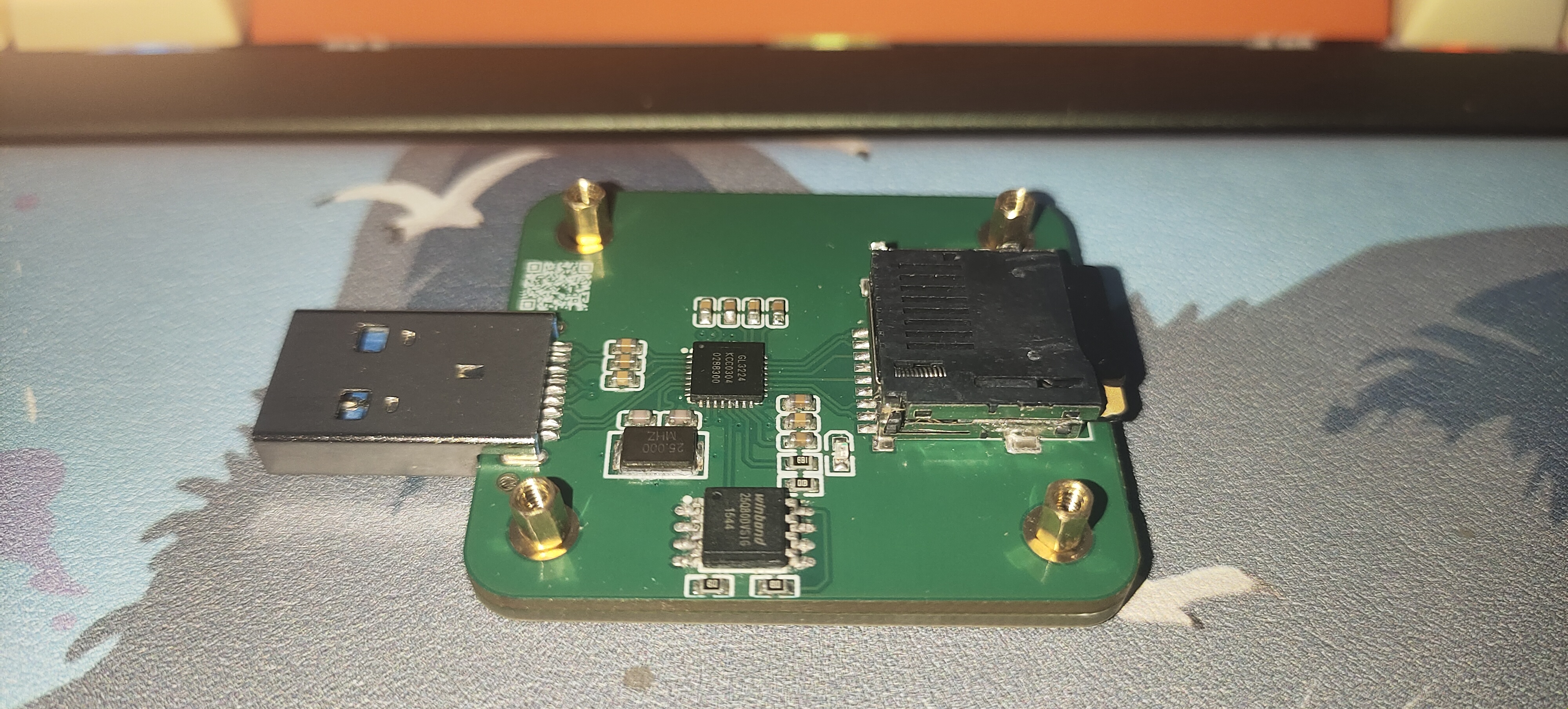
Xilinx's JTAG adapter board supports 14-pin standard JTAG and various interfaces.
Xilinx devices use a JTAG interface for downloading, but the interfaces of various FPGA development boards are not compatible. Various interfaces are commonly available, such as 6-pin JTAG, 14-pin JTAG, and 10-pin JTAG.
This adapter board implements a 6-pin JTAG (compatible with Milink), an 8-pin JTAG (compatible with mining boards), a 14-pin JTAG (compatible with Digilent and official evaluation boards, as well as most development boards), and a 10-pin
JTAG interface used by some low-cost DIY programmers and some development boards from Xiaomeige. Essentially, the board does not contain any active components. I also tried using an Altera USB-Blaster 10-pin JTAG jumper for downloading, which still worked normally (not guaranteed for every board, and no guarantee for Xilinx). All the development boards and programmers I have can recognize the devices and download normally. This includes ISE, Vivado, Zynq 7000 series, and Spartan 6 series; other devices have not been tested. The programmer is a simple FT232 programmer.
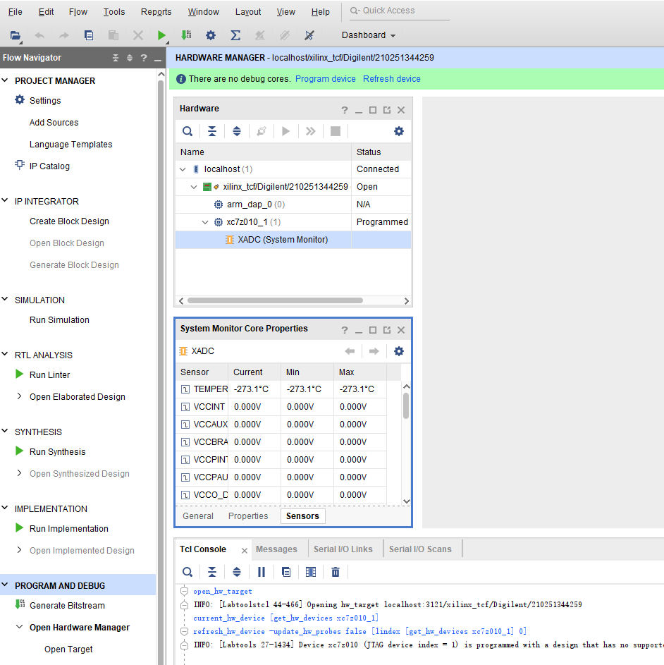
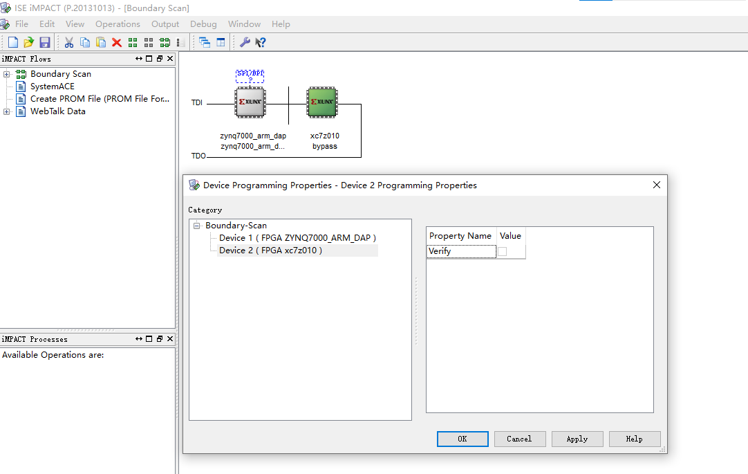
See the attached screenshots. In my setup, only one of ISE and Vivado can recognize the device; one driver cannot run both software programs simultaneously. I've also attached the drivers for both downloaders here.
![Vivado Recognition]
![ISE Recognition]
install_digilent.exe
Screenshot 2024-06-19 161855.png
Screenshot 2024-06-19 162309.png
Screenshot 2024-06-19 163514.png
install_digilent.exe
IMG_20240619_161937.jpg
IMG_20240619_162253.jpg
IMG_20240619_164043.jpg
PDF_Xilinx-JTAG-Debugger-Converter.zip
Altium_Xilinx-JTAG-Debugger-Converter.zip
PADS_Xilinx-JTAG-Debugger-Converter.zip
BOM_Xilinx-JTAG-Debugger-Converter.xlsx
94162
Summer outdoor camping cooling and storm-proof fan (6108724A)
Not only can it quickly cool you down, but its unique shape also allows it to be quickly deployed to intimidate others in case of danger, scaring them out of their wits. Hence, it is called a riot control fan.
In the sweltering summer, outdoor camping requires an essential item for quick cooling and heat dissipation, thus the Summer Outdoor Camping Cooling and Heat Protection Fan was born.
Production Statement: This project is an entry for the "Summer Electronic Fun Project." Due to the tight deadline, some parts of the fan shell were 3D printed and then manually modified. Therefore, the 3D model of the shell will be updated and uploaded after all details are perfected. This is
my first attempt, so please provide guidance!
Materials needed: Modified high-voltage brushless ducted motor, homemade ducted motor control board, homemade motor PWM speed controller, DC-DC boost board, 3D printed shell, limit switch, 18650 battery, voltmeter, LED indicator.
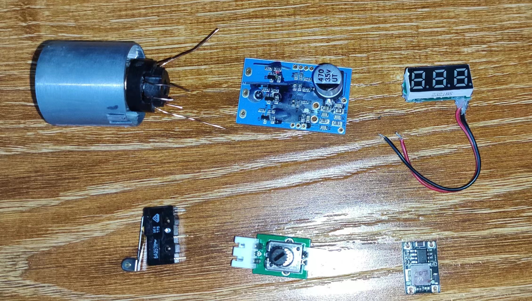
Fan Motor: A 110V high-voltage brushless ducted motor with a 100,000 RPM purchased online was disassembled and painstakingly rewound with 0.5mm enameled wire to convert it into a 12V low-voltage brushless ducted motor for this project's fan.

Ductless Motor Control Board: I researched and learned about brushless ESCs online, drew the brushless ESC MOS circuit, and arranged the components to the minimum possible size for easy installation within the housing.
Motor PWM Speed Controller: Provides PWM output signals to the ductless fan control board for airflow regulation.
DC-DC Boost Board: Due to limited housing space, it was impossible to place four 18650 batteries to power the fan. Initial testing with two 18650 batteries at 7.4V showed insufficient airflow. After consideration, I purchased a DC boost circuit module to boost the 7.4V to 12V, improving airflow.
Battery: Two 18650 batteries were connected in series to form a 7.4V battery. 3D Printed Housing: I studied SolidWorks tutorial videos and modified existing housing prototypes from foreign model websites to complete the modeling and printing of the fan housing. After manual secondary cutting, it was adapted to fit the assembly of the internal fan components.
test.mp4
Violent Fan Gun.3mf
PDF_Summer Outdoor Camping Cooling and Stormproof Fan (6108724A).zip
Altium_Summer Outdoor Camping Cooling and Stormproof Fan (6108724A).zip
PADS_Summer Outdoor Camping Cooling and Stormproof Fan (6108724A).zip
BOM_Summer Outdoor Camping Cooling and Stormproof Fan (6108724A).xlsx
94163
2023 Electronic Design Contest, Problem J: [Automatic Line Fault Detection System] - Equal Length Difference Team
2023 National Electronic Design Contest, Problem J: [Automatic Circuit Fault Detection System] - This project utilizes common components, a simple structure, and low cost to meet the requirements of the problem.
I. Introduction to
the 2023 National Electronic Design Contest, Problem J: [Automatic Circuit Fault Detection System]
This work entered the national finals, but was stopped at the second level due to a program bug
. This bug has now been fixed.
This work uses common components and fulfills all the requirements of the problem. Power supply only requires a Type-C USB connection, making it low-cost to manufacture and suitable for replication and reproduction.
II. Problem Requirements
Basic Requirements:
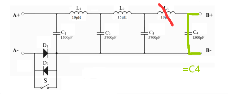
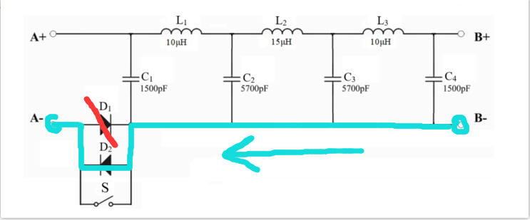
In Figure 1, switch S is closed. Only one inductor or capacitor is faulty in the circuit network.
After pressing the start button, the system automatically detects and displays the faulty component number and fault type (open circuit or short circuit).
Advanced Section:
Switch S is open.
One diode in the circuit network has an open circuit fault. Simultaneously, one inductor or capacitor is faulty. After pressing the start button, the system automatically detects and displays the faulty component number and fault type.
The circuit network may be fault-free, or only one inductor or capacitor is faulty, or one diode has an open circuit fault while another inductor or capacitor is faulty.
After pressing the start button, the system automatically detects and displays the system status (whether there is a fault), and the faulty component number and fault type when a fault is present.
Other.
III. Design Summary:
The overall structure is simple, using common components, and fulfilling the requirements of the problem at low cost.
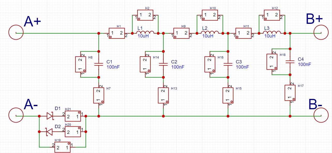
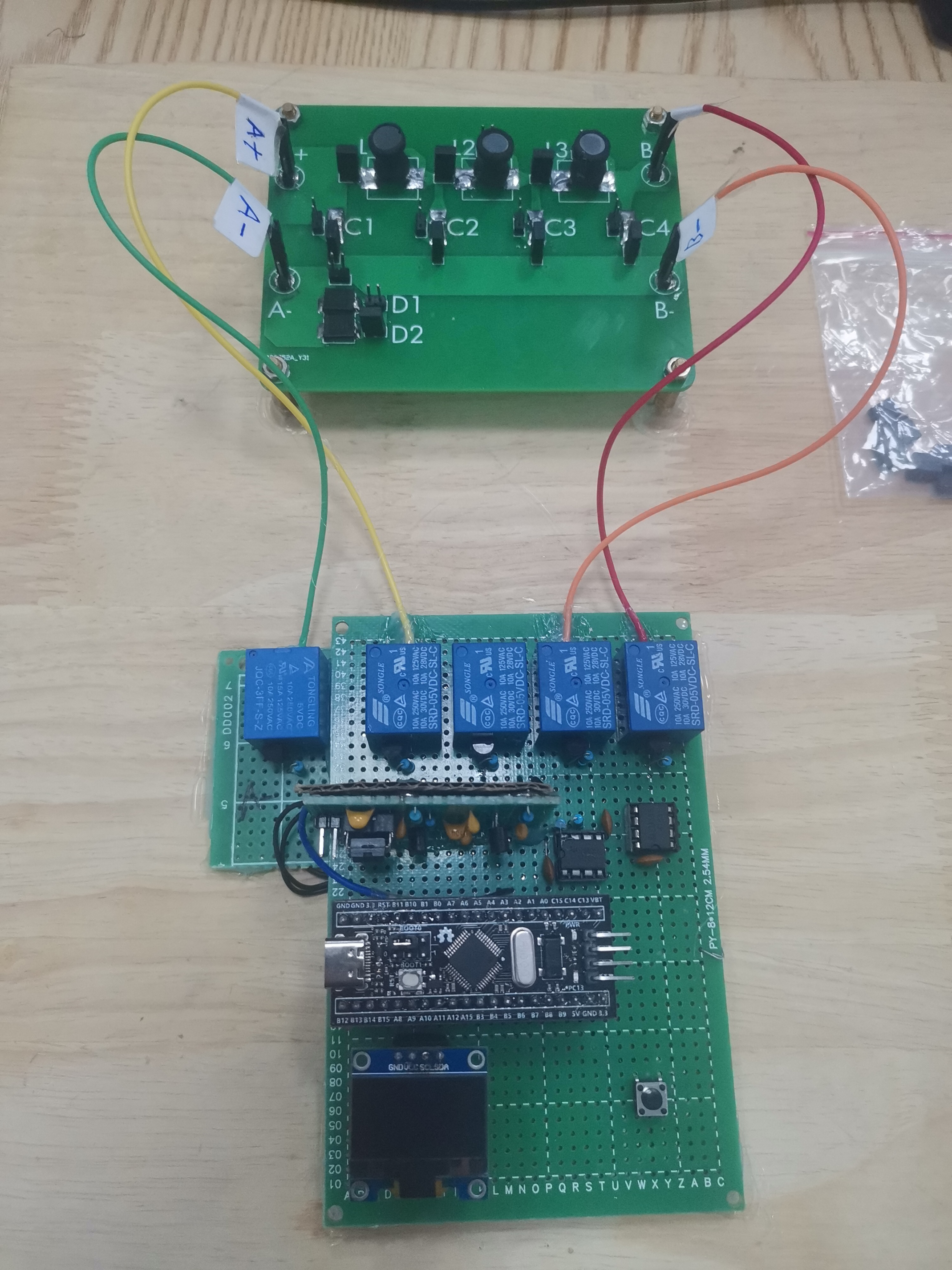
This system uses the STM32F103 as the control core of the entire design. The entire system consists of the main control chip system circuit, signal buffer circuit, ADC sampling circuit, relay control multiplexing circuit, capacitance measurement circuit, resistance measurement circuit, keypad circuit, and display circuit.
Two measurement methods are combined in the design. The first is the resonance method, where a 720kHz square wave signal is generated by the microcontroller's timer and sent to the circuit under test. ADC sampling is performed at the output, i.e., the digital value of the output voltage of the sampling circuit. Repeated testing is conducted to establish a sample model, which is then compared and judged in actual testing.
The second is the measurement method, which substitutes the corresponding circuit under test into the capacitance and inductance measurement circuits to compare the values of some fault points, judging and displaying the fault location and type of the circuit under test.
Combining these two detection methods, the fault location and type of the circuit under test are accurately determined and displayed. After multiple debugging sessions, the expected functions of the measurement system are achieved.
It is recommended to use surface-mount capacitors (accuracy: ±10%) and I-type inductors (accuracy: ±10%) connected in series and parallel to meet the requirements of the problem.
Since there are inherent errors in the manufacturing of capacitors and inductors, the frequency of the injected square wave signal needs to be adjusted according to your own board, approximately 600kHz~900kHz. The output signal will differ at different frequencies. Multiple frequencies can be used for multiple measurements to increase accuracy.
The measurement of capacitors and inductors does not require deducing the exact value; only the approximate values under various conditions need to be compared to infer the fault location and type.
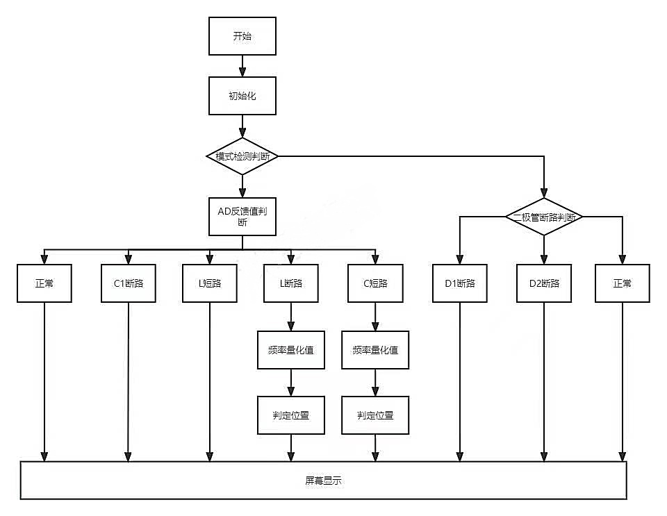
Fourth, the measurement flowchart:

First, inject a 720kHz square wave through A+, output through B+, ground through B-, buffer the signal, and then sample it with the ADC. By comparing the peak-to-peak values of the signal, a short circuit in the inductor and an open circuit in the capacitor can be determined.
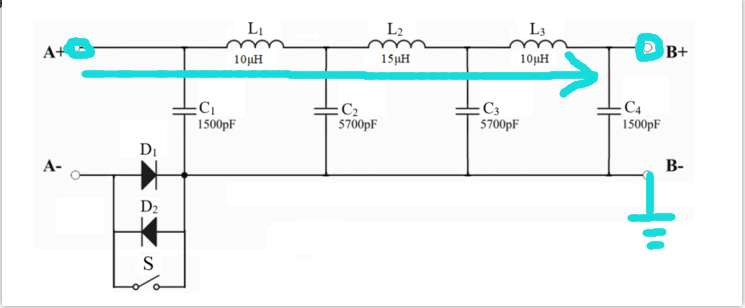
If the ADC feedback is 4096, it indicates no signal at the B+ terminal, and the capacitance measurement stage begins: turn off signal generation, measure the total capacitance from B+ to B-, and deduce the location of the open circuit in the inductor.

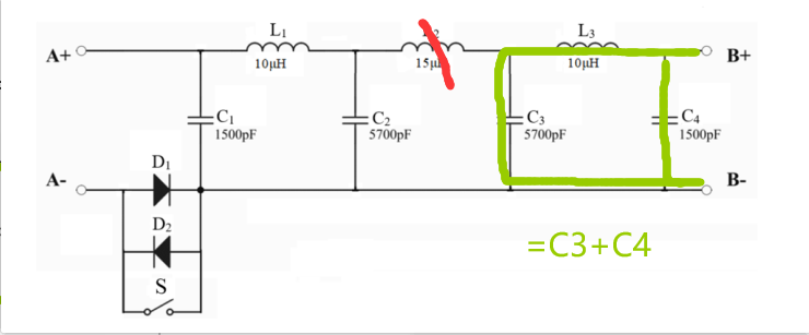
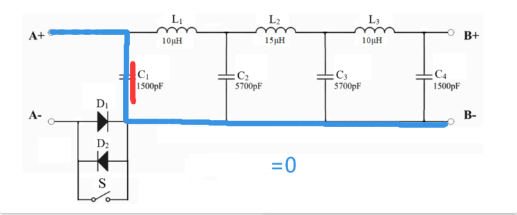
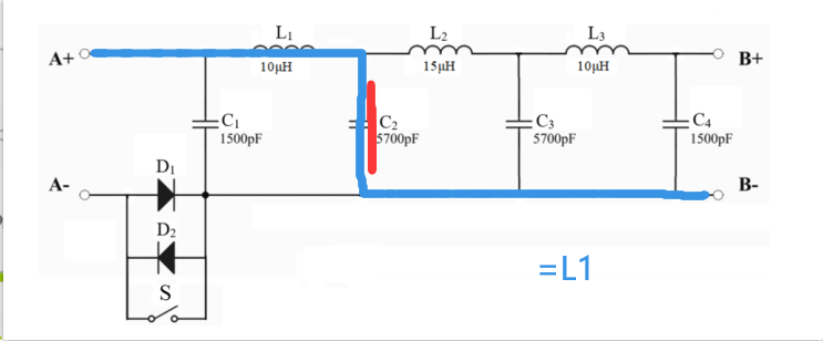
If the ADC feedback is 0, it indicates that B+ is grounded, and the inductance measurement stage begins: Signal generation is turned off, A+ is connected to 3.3V, and B- is connected to the inductance measurement circuit. By comparing the inductance values, the location of the capacitor open circuit can be deduced.


For diode testing: Signal generation is turned off, A- is pulled high, and the B- level is measured to infer whether D1 is faulty; then B- is pulled high again, and the A- level is measured to infer whether D2 is faulty.

Fifth, Problem Analysis:
The problem is an automatic fault detection system for equivalent network circuits of signal transmission lines, which must be related to signals. According to the equivalent model, it is highly likely related to parameters such as impedance.
By observing the circuit diagram, multiple measurements of different parameters can be used to infer the fault location and type.
Another method is to measure the voltage difference and current phase, which should be feasible, but I have not verified it.
Sixth, Hardware Circuit Composition

: The measurement system mainly consists of a microcontroller minimum system, a multiplexing circuit, a capacitance measurement circuit, and a capacitance measurement circuit.
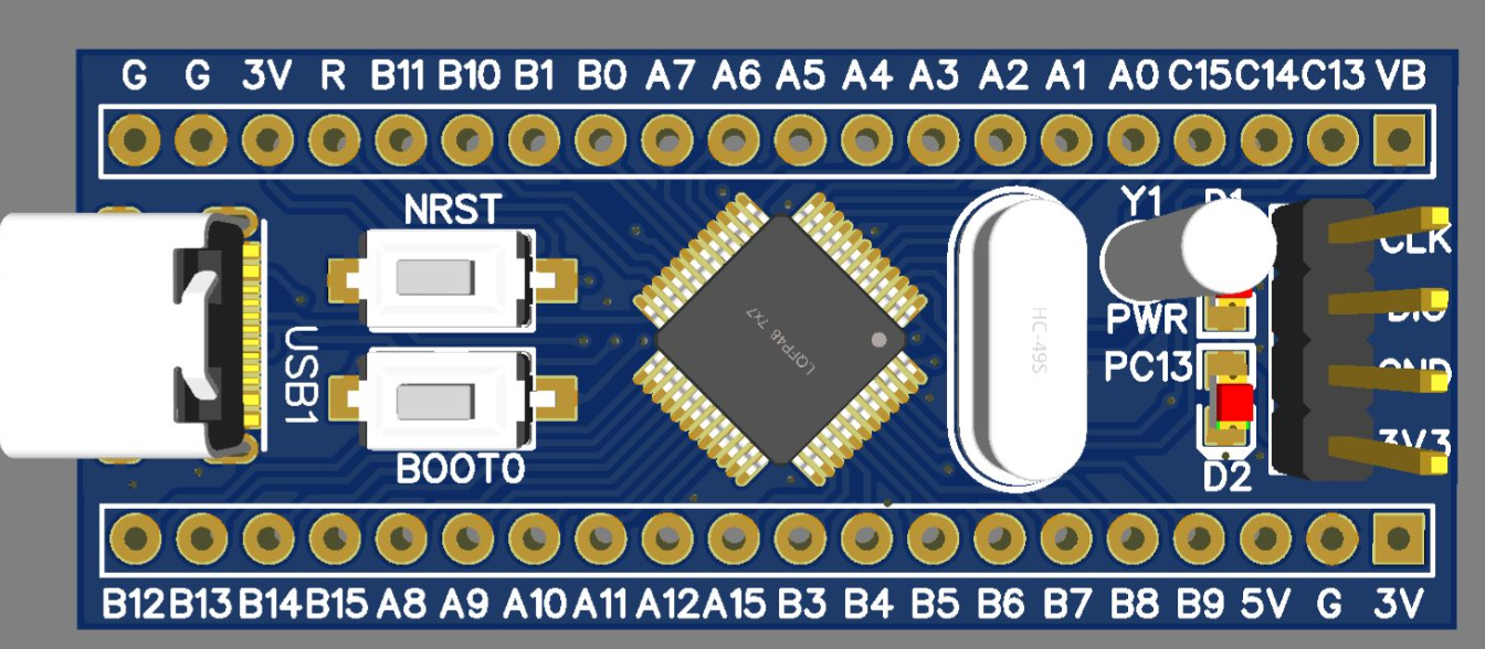
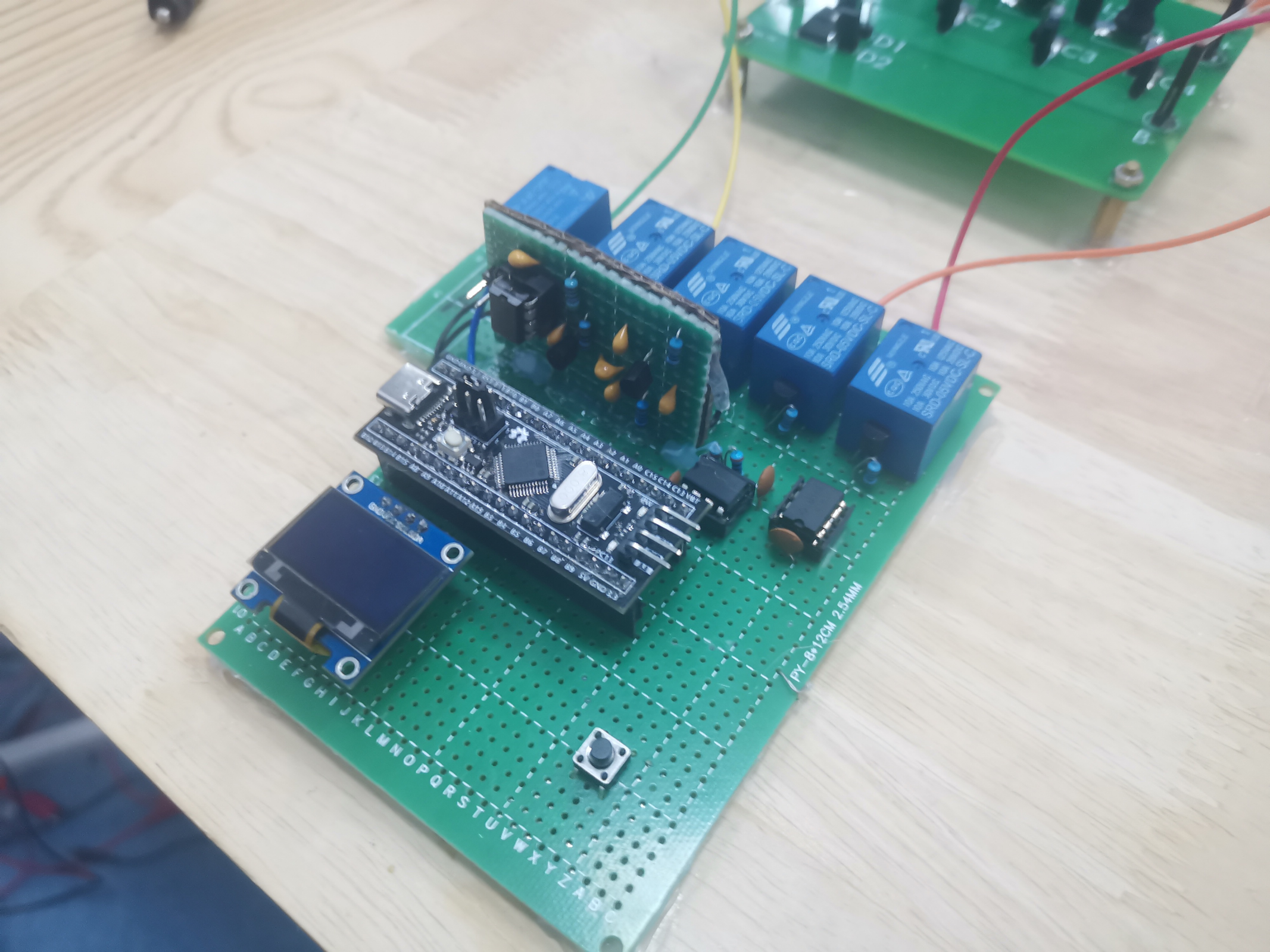
The microcontroller minimum system is a BluePill board
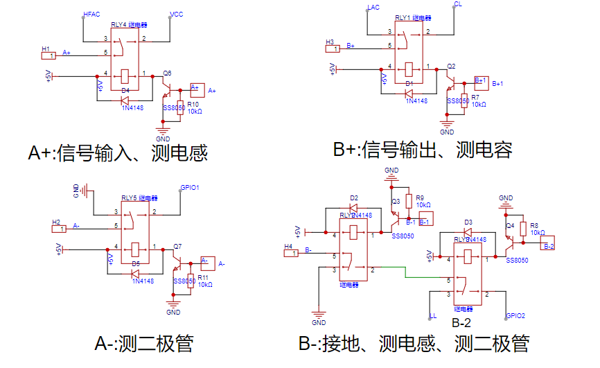
that uses relays to implement multiplexing
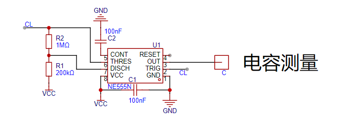
and a multivibrator NE555. The frequency of the output square wave is used to infer the capacitance of the line.
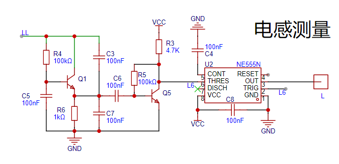
Using a three-point resonant circuit, the NE555 is used as a Schmitt trigger, and the output frequency is used to inversely determine the inductor value.
Seven, Program Flowchart; Eight
, Physical Demonstration

; Nine, Attachments
: Attachment 1: Program Source Code (Keil with STM32CubeMX); Attachment 2: Demo Video.
source code.zip
VID_20230905_091443.mp4
PDF_【2023 Electronic Engineering Contest】2023 Electronic Engineering Contest Problem J【Automatic Line Fault Detection System】.zip
Altium_【2023 Electronic Engineering Contest】2023 Electronic Engineering Contest Problem J【Automatic Circuit Fault Detection System】.zip
PADS_【2023 Electronic Engineering Contest】2023 Electronic Engineering Contest Problem J【Automatic Line Fault Detection System】.zip
BOM_【2023 Electronic Engineering Contest】2023 Electronic Engineering Contest Problem J【Automatic Line Fault Detection System】.xlsx
94164
19pad numeric keypad
A numeric keypad made using an APM32F103CBT6, with a 3D-printed casing and gasket structure.
A numeric keypad was made using an APM32F103CBT6 microcontroller. The outer shell and gasket structure
positioning plate were 3D printed. Cotton strips/silicone pellets were used.
The crystal oscillator in the BOM was replaced with an 8MHz
oscillator with an SH1.0 interface. The wiring sequence can be found in the schematic/PCB diagram.
real21_vial.bin
New version of positioning plate.step
New version of top cover.step
New version of bottom cover.step
Gerber_PCB1_2024-04-13.zip
PDF_19pad Numeric Keypad.zip
Altium_19pad numeric keypad.zip
PADS_19pad numeric keypad.zip
BOM_19pad numeric keypad.xlsx
94165
electronic


 3. Other


 京公网安备 11010802033920号

 A15-0007-201


