Design Rationale:
Originally, I wanted to utilize an idle fan to create a miniature version for easy assembly with fan blades. However, considering the potential for battery drain with an embedded battery, I opted for a Type-C input for power, compatible with power banks. Two versions were designed: a simplified version without an MCU and requiring no programming, and an optimized version using an Air001 to generate PWM for driving and adding other peripheral functions, allowing for more comprehensive functionality. Both versions support adjustable fan speed and can be used for tasks like welding smoke extraction, cooling in summer, etc. The Air001 version can power LEDs for illumination or UV curing (the UV LEDs are external and not yet implemented; only control code is added). The
simplified version works as follows:
First, a 5V voltage is connected and boosted to 12V via an MT3608 to power the fan. Simultaneously, the 5V voltage powers a GP9101. A variable resistor is used to change the PWM duty cycle of the GP9101, thus adjusting the fan speed. The fan is a 4-wire PWM fan,
version Air001.
The 5V is stepped down to 3.3V via an LDO to power the Air001, and simultaneously boosted to 12V to power the fan. The Air001 emits PWM to control the fan speed. Each button press increases the duty cycle by 20%,
returning it to 0% after reaching 100%. The indicator light brightness changes with the duty cycle to indicate fan speed. A WST3400 is used to control the external UV lamp (which is not soldered).
Attached are demonstration videos for both versions, as well as the code for the Air001 version.
Several problems were encountered during the construction process. It was discovered that the 100k resistor in the package purchased online was incorrect; it was labeled 100k but was actually 100R, which could not be used for proper voltage boosting. A 0603-sized resistor was found and reinstalled. However, the GP9101 chip in the simplified version was faulty and could not adjust the speed. After purchasing a new one, it finally worked. However, due to repeated soldering and my desire for simplicity, the soldering time on the heating plate was too long. Several potentiometers were damaged (melted). There was also another issue: initially, I didn't understand fan rotation direction control and mistakenly thought adjusting the PWM duty cycle to be complementary would suffice. In reality, a 4-wire PWM fan cannot easily change direction; only a 2-wire fan can change direction by swapping VCC and GND. Therefore, the initial direction-changing function was removed from the project. I didn't even solder the direction-switching switch on my board.
The Air version also encountered many difficulties.
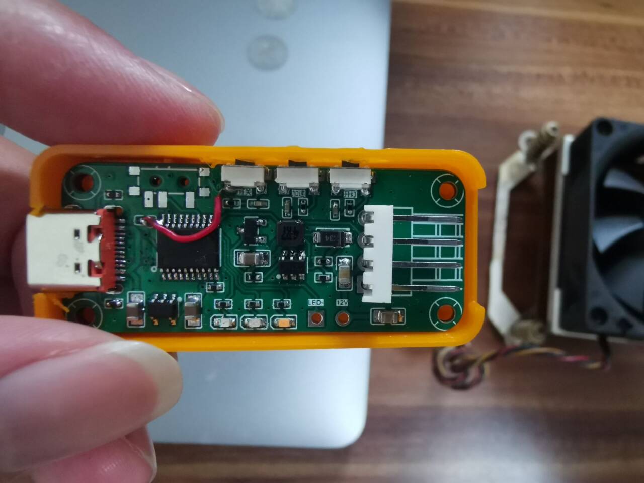
After soldering, I discovered the circuit was drawn incorrectly, and the main controller lacked 3.3V power, requiring jumper wires to solve the problem (the schematic and PCB have been corrected in the project). With the hardware issues resolved, the software was also stuck for a long time. I studied the PWM code extensively and felt it was correct. The only problem was the LEDs not lighting up (during development, I used LED brightness as a duty cycle indicator). After investigation, I found that the LEDs wouldn't light up when the brake was activated. Therefore, I disabled the brake function. The PWM successfully drove the fan. I also added a breathing light effect, etc., all in the code project.
[Image of the simplified version] [
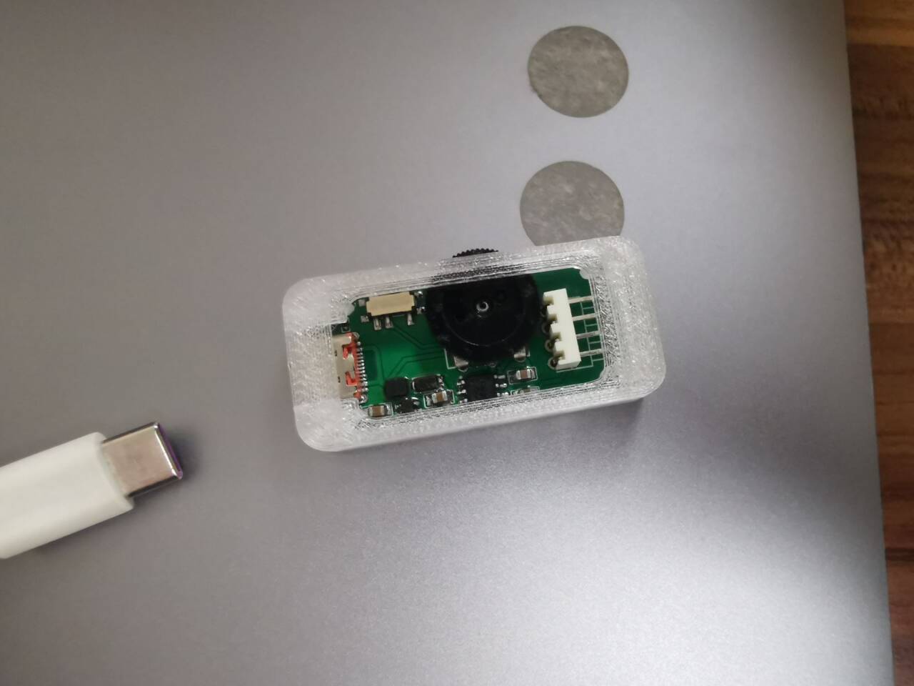
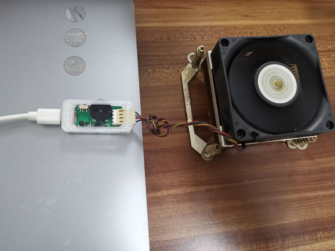
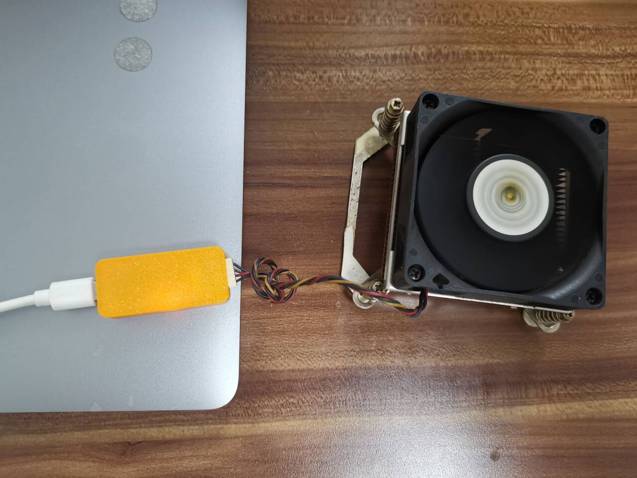
Image of the Air001 version]

QQ Video 20240618015715.mp4
QQ Video 20240618015723.mp4
PWM Fan Controller.zip
PDF_Portable Fan Driver Module.zip
Altium_Portable Fan Driver Module.zip
PADS_Portable Fan Driver Module.zip
94210
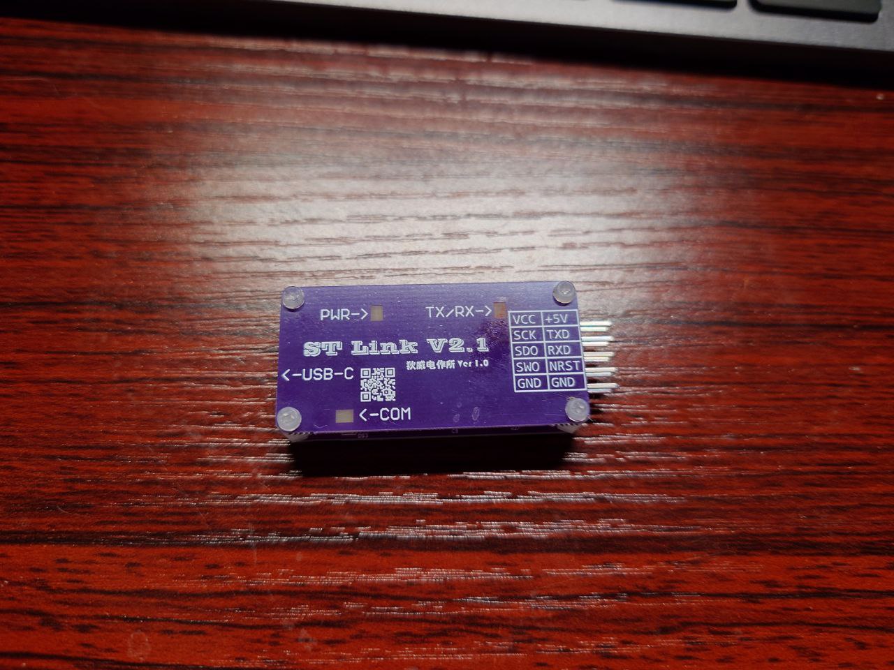
DIY STLinkV2.1
A self-made ST-Link V2.1 development tool for ST microcontroller development, debugging, and serial port connection.
Project Description:
This project is a self-made ST-Link V2.1 project, primarily designed to address the developer's (my) needs for ST-Link tools. Key development goals included:
ensuring the debug output interface arrangement conformed to the developer's (my) preferred configuration;
enabling connection to a PC via the USB-C port
; and providing a serial port to minimize the need for additional serial port connections.
Based on these requirements, the developer (myself) decided to redesign the circuitry based on the ST-Link V2.1 hardware design to create a custom ST-Link device. Project Demonstration:
The schematics and PCB layout for this project have been uploaded to LCSC and can be viewed directly.
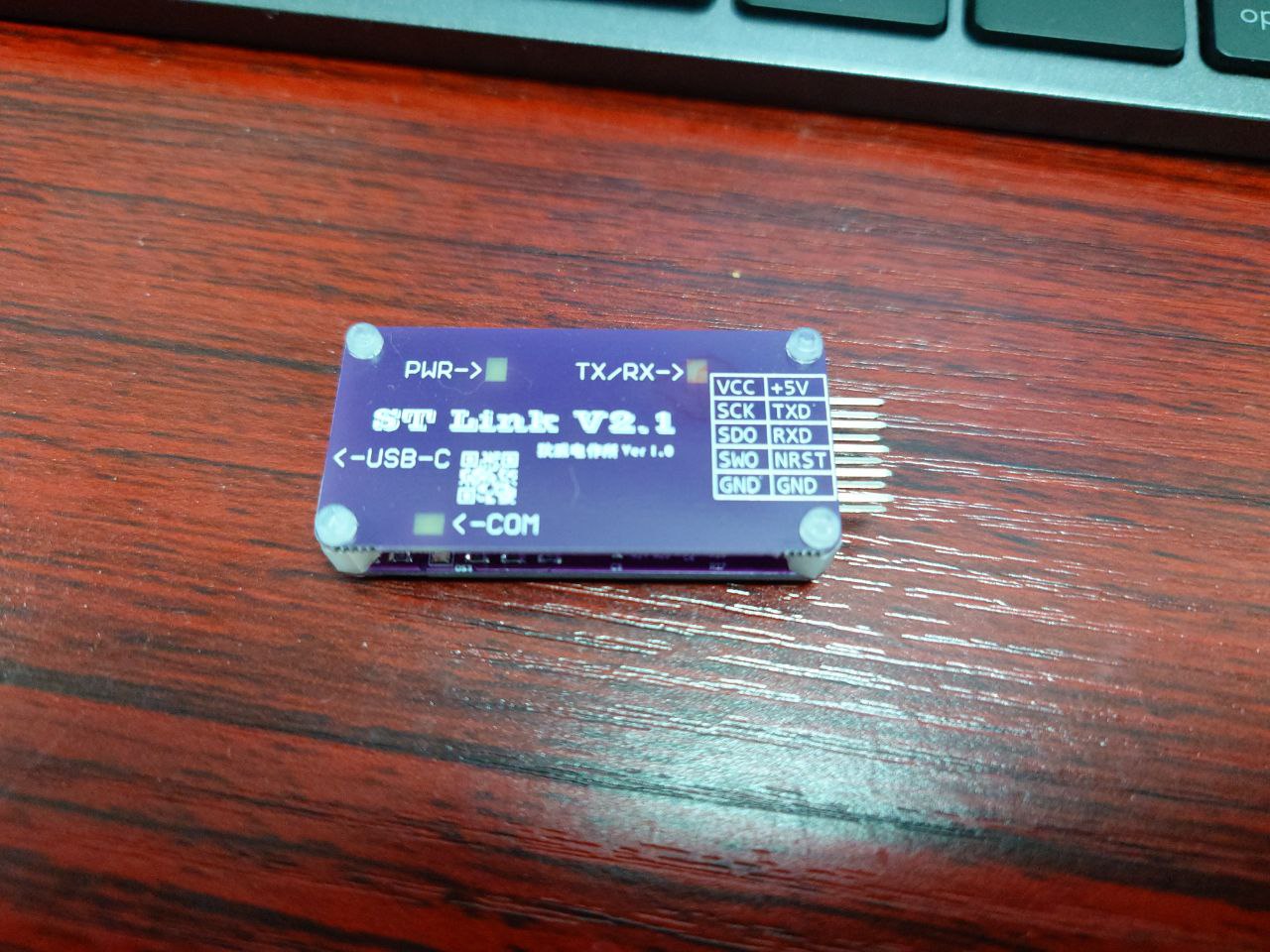
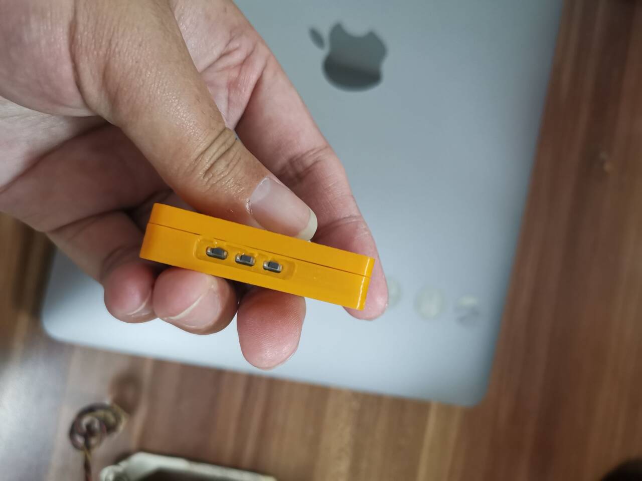
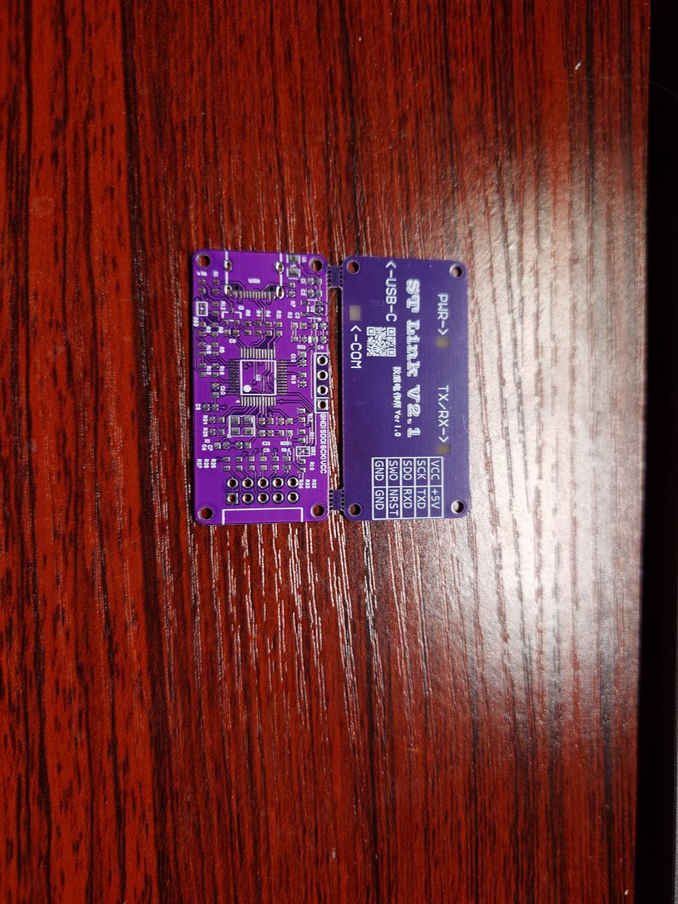
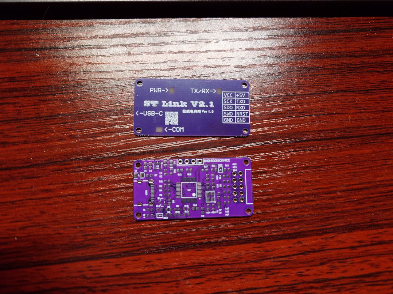
The above shows the assembled state. The
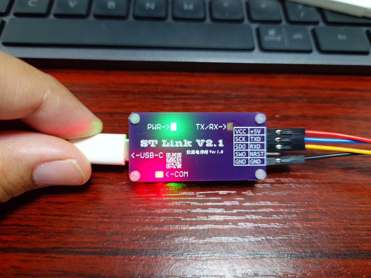
above also shows the intended state in use. The LED design has slight flaws
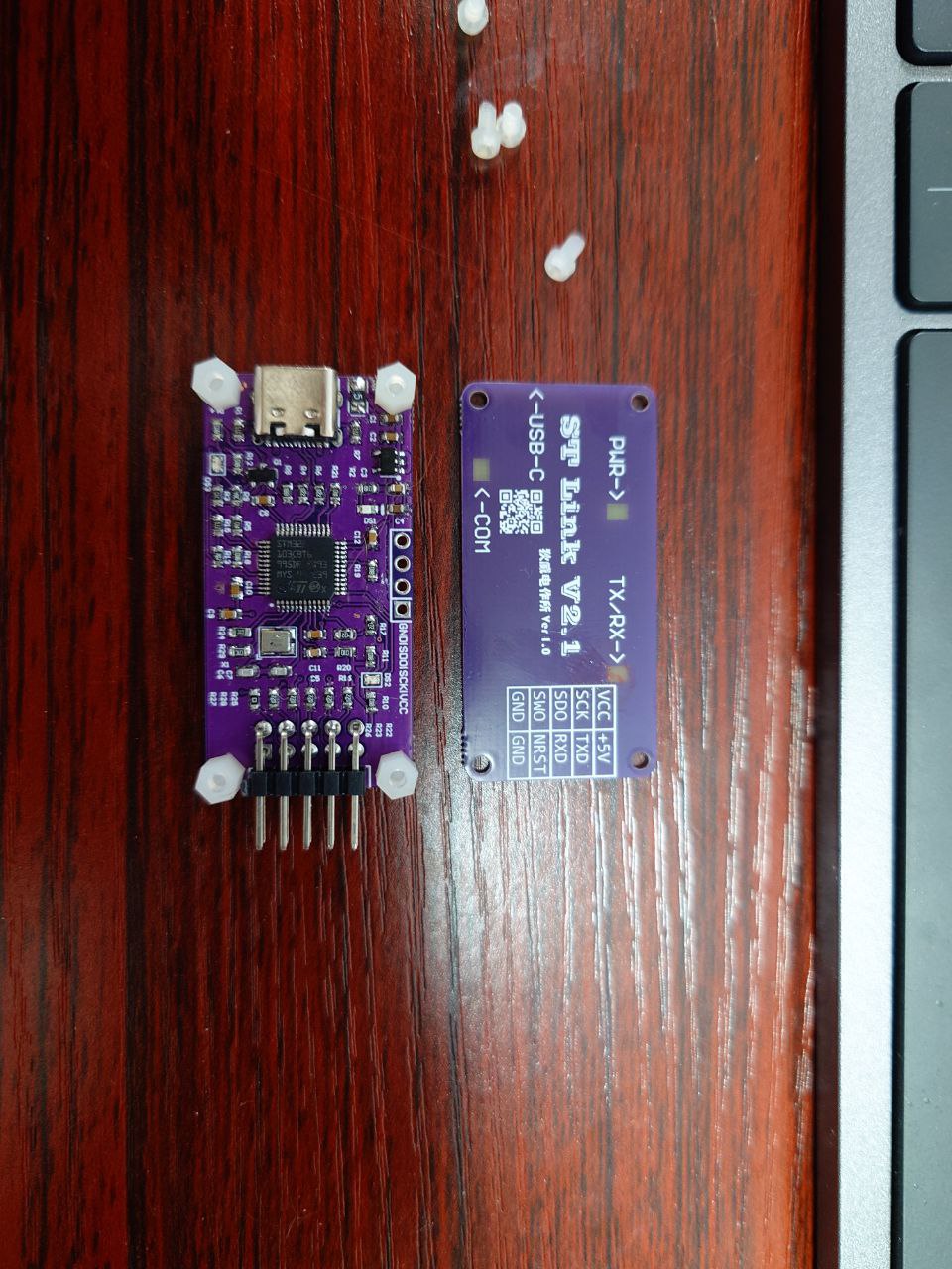
. The above shows the board and internal components.

The diagram also connects to the STM32's SWD debugging and serial port, reducing wiring complexity.

Serial port debugging is used
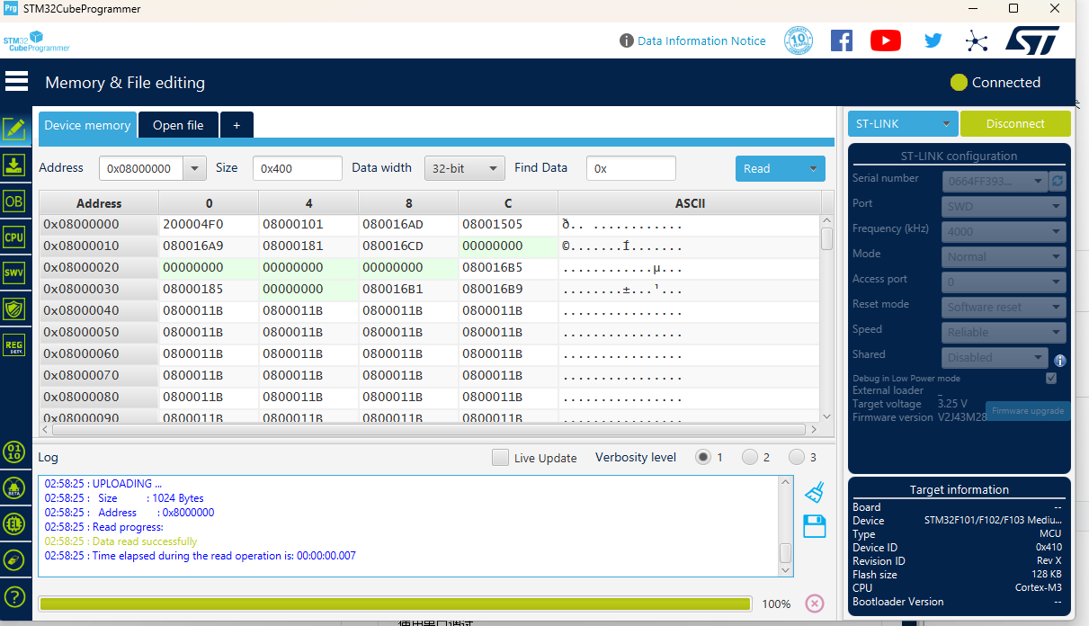
via the cube programmer.
Project creation (Simplified)
was done by obtaining the pre-made PCB from JLCPCB.
The PCB was disassembled and
components were soldered.
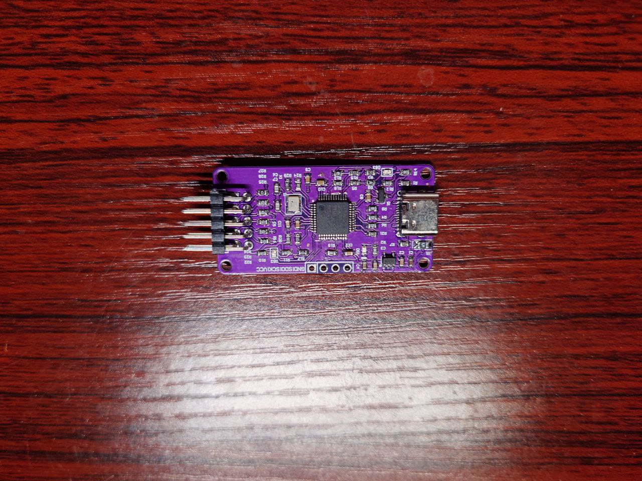
Eight M24 nylon screws and four M26 nylon studs were prepared and

assembled .
The firmware in the attachment was burned using an existing ST-Link. The author's evaluation : After board testing, all hardware functions were normal (SWD debugging and virtual serial port). The

corresponding firmware allows for drag-and-drop burning from a USB flash drive, basically meeting the designer's (my) requirements. The firmware used is in the attachment and needs to be burned via an existing SL-Link or other methods through the SWD interface.
STLinkV2.J28.M18_Firmware.zip
PDF_DIY STLinkV2.1.zip
Altium_DIY STLinkV2.1.zip
PADS_DIY STLinkV2.1.zip
BOM_DIY STLinkV2.1.xlsx
94211
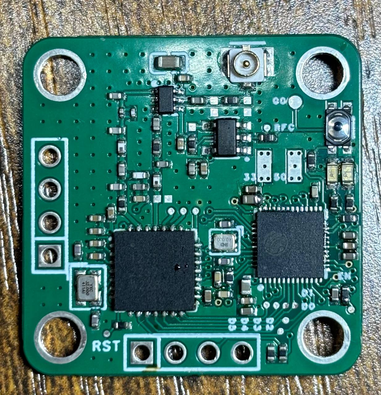
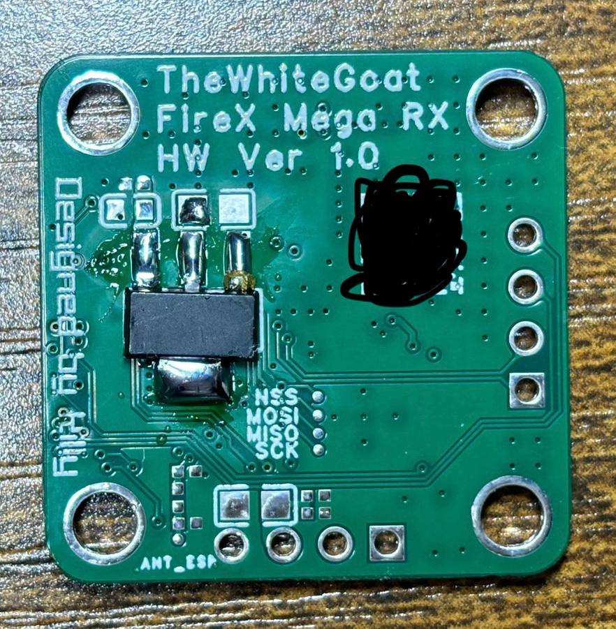
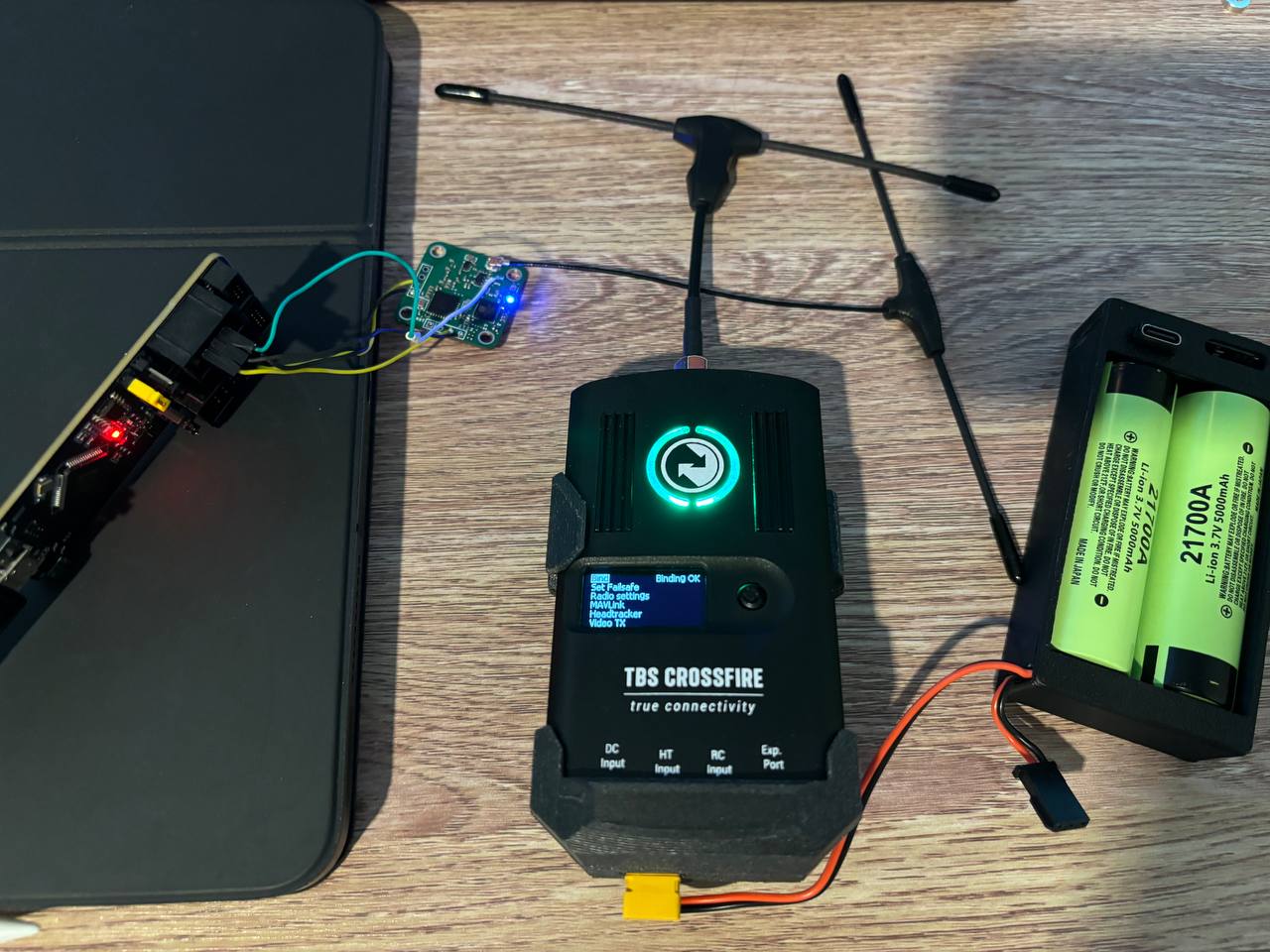
ESP32+SX1272 915MHz LoRa ELRS Development Board
This is a LoRa RF development board based on ESP32 and SX1272 , operating at 915MHz and compatible with the ELRS protocol. It has no connection to BlackShell TBS Crossfire.
This is an RF LoRa development board based on ESP32 and SX1272. It has no connection to the BlackShell TBS Crossfire and
is theoretically compatible with ELRS, but requires custom firmware compilation and configuration modifications. The design purpose is solely for learning RF circuits and microcontroller development; only the hardware is open-source, not the software.
The protocol is based on the Public Domain; feel free to modify it as you see fit, and the author assumes no responsibility.
Accordingly, for legal reasons, the author will not provide any BlackShell software or firmware, although reverse engineering is not difficult. The specific process cannot be provided due to legal reasons, nor can I provide the key or related procedures, but there are methods for decryption that are relatively simple. Readers can extract the firmware themselves from various resources, including the ESP32 datasheet and reference materials.
In short, the new BlackShell receiver uses an ESP32 for control and an SX1272 for the RF front-end, handling 915MHz band transmission and reception activities. The hardware is very similar to the ELRS 915 series.
Devboard based on ESP32 & SX1272, HAVE ABSOLUTELY NO CONNECTION WITH TBS CROSSFIRE.
The design purpose is only for learning RF circuity and MCU development, only hardware is open-sourced, and no software will be provided.
The agreement is based on Public Domain. Please feel free to modify and play with it. The author does not take any responsibility for any form of the project.
Accordingly, the author will not provide any form of software and firmware support, but it is not difficult to figure out or write your own.
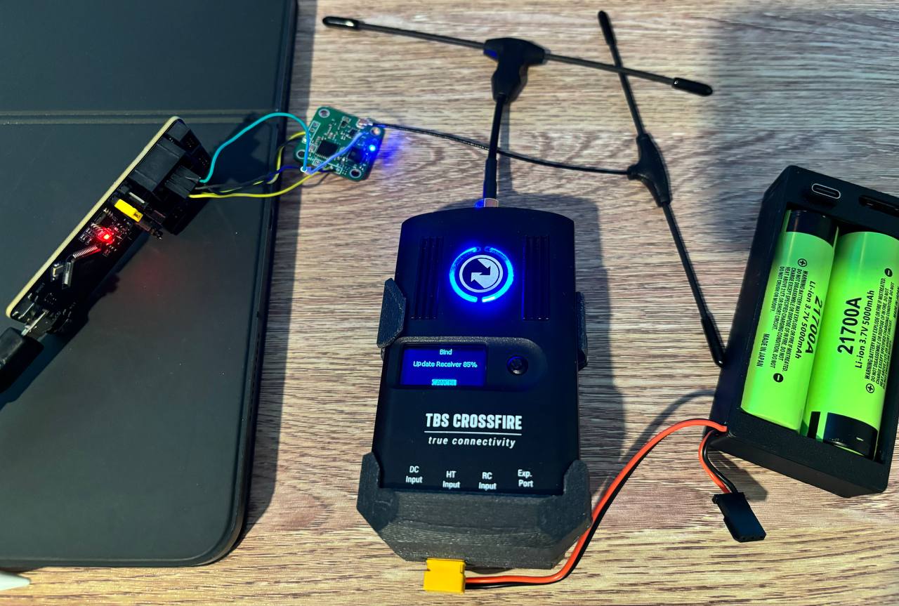
Successfully tested and flashed, updated firmware.
PDF_ESP32+SX1272 915MHz LoRa ELRS Development Board.zip
Altium_ESP32+SX1272 915MHz LoRa ELRS Development Board.zip
PADS_ESP32+SX1272 915MHz LoRa ELRS Development Board.zip
BOM_ESP32+SX1272 915MHz LoRa ELRS Development Board.xlsx
94212
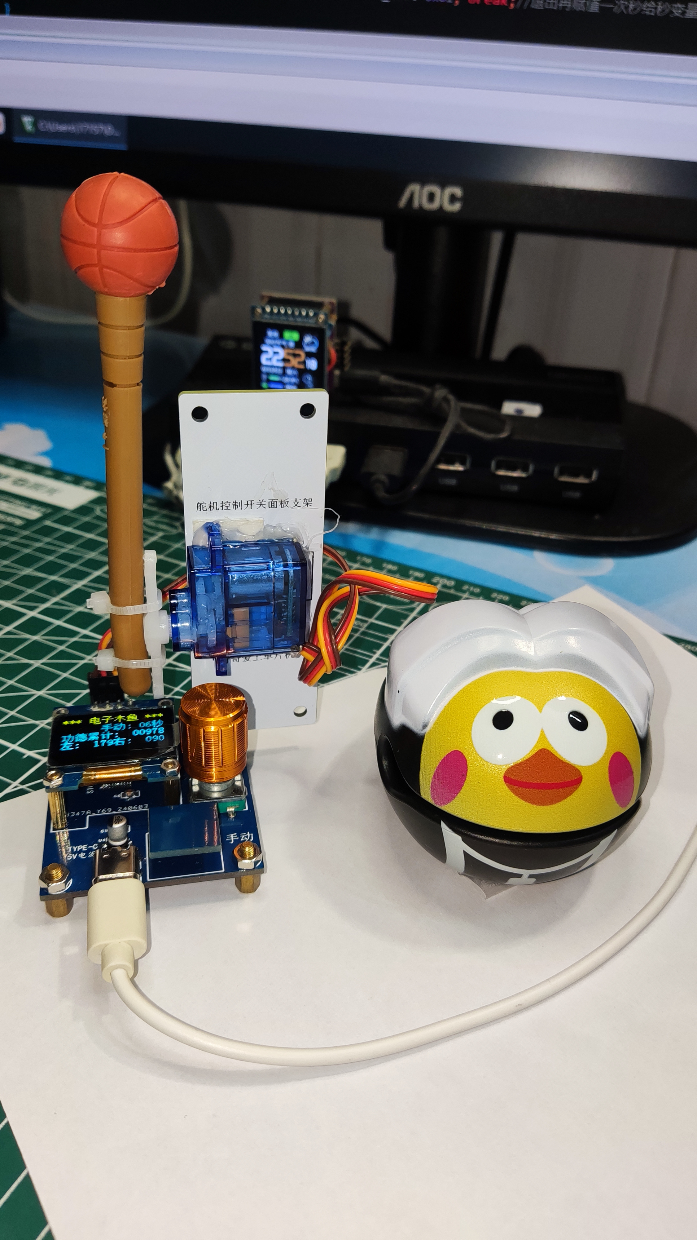
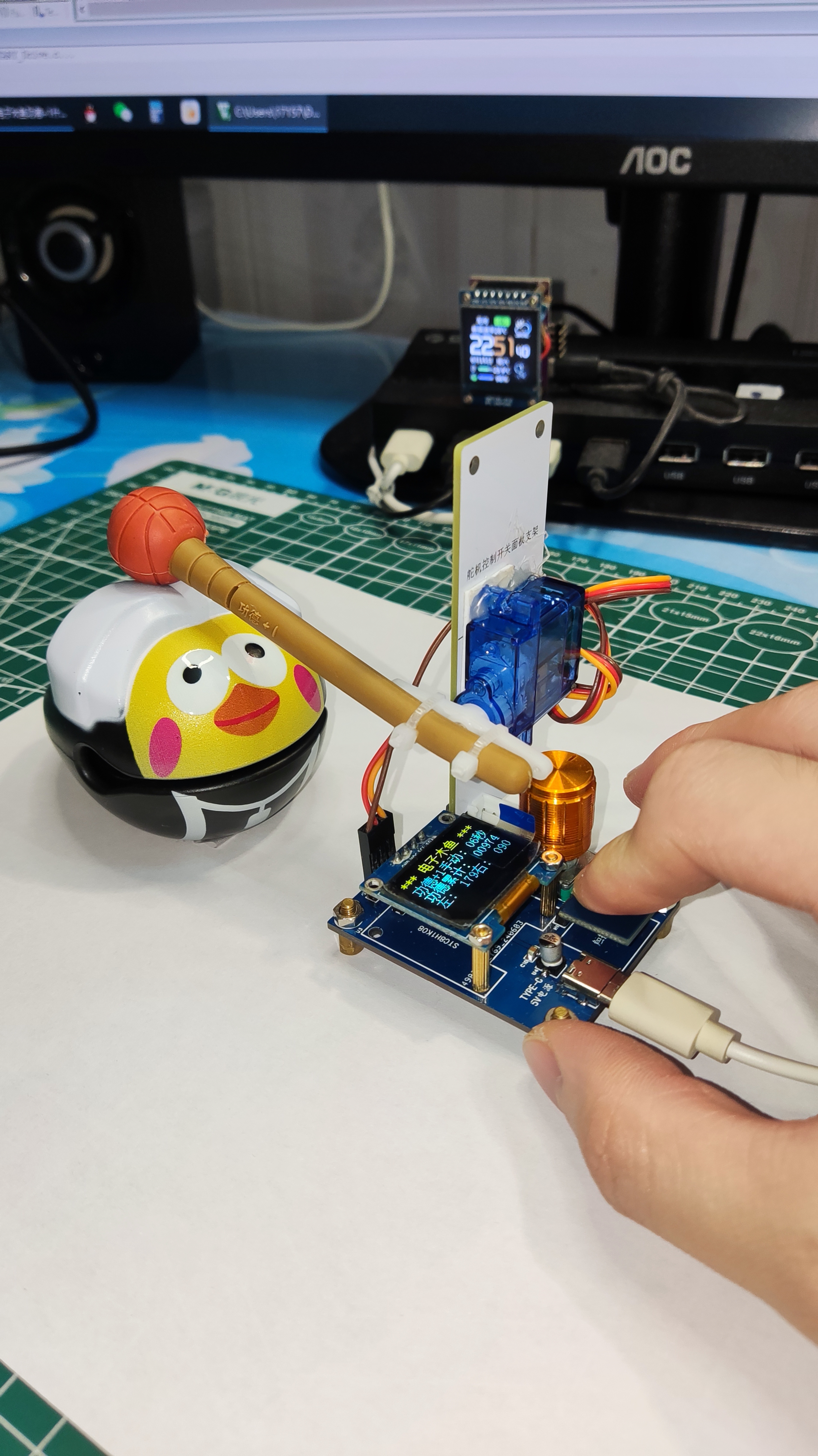
Electronic wooden fish
SG90 servo motor + STC8H1K08
As a microcontroller enthusiast, I often encounter compilation errors, so I've decided to contribute to the microcontroller community through simple typing.
The solution uses an SG90 servo motor and an STC8H1K08 microcontroller, featuring automatic and manual modes, a menu function, real-time fine-tuning of the servo motor's angle, and EEPROM power-off memory .
A short press of the rotary encoder switches between manual and automatic modes, while a long press enters the menu. The first step adjusts the automatic timer, the second adjusts the angle value on the left side of the servo motor, and the third adjusts the angle value on the right side. The data can be adjusted by turning the knob left and right, and a long press exits the automatic mode. The automatic timer range is 0-99 seconds. The servo motor angle range is 0-200 degrees.
The code is written in 51C language and includes a system adjustment menu—it's quite fun.

//The source code and PCB layout for the above projects are publicly available. Search for the username "Qiqi Loves Microcontrollers" on the "LCSC Open Source Hardware Platform".//Microcontroller model: STC8G1K08 1. When programming, be sure to select built-in IRC=30MHz. 2. Set the reset pin to the IO port. 3. Uncheck the option to erase the user EEPROM area when downloading the user program
. /*No technical support provided, just sharing for fun. This is an open-source blogger's work; it is for use only and not for commercial purposes. Questions can be discussed in the comments section below. Designer of this solution: Qiqi
Douyin: The Cutest Qiqi in the Universe Kuaishou ID: Qiqi Loves Microcontrollers Bilibili: Qiqi Loves Microcontrollers QQ: 1715755109 (For custom microcontroller programs and PCB designs, add as a friend and indicate your purpose; paid design, serious inquiries only). QQ Group: 499067314 (Welcome all microcontroller enthusiasts to join the group; group files are available for free download.) */
Electronic Wooden Fish.zip
Single-chip microcomputer electronic wooden fish presentation video.mp4
IMG_20240615_225140.jpg
IMG_20240615_225218.jpg
PDF_Electronic Wooden Fish.zip
Altium_Electronic Wooden Fish.zip
PADS_Electronic Wooden Fish.zip
BOM_Electronic Wooden Fish.xlsx
94213
electronic


 京公网安备 11010802033920号

 2SA1464


