Note: The fan casing uses a cheap lithium battery portable fan available on Taobao. If the appearance is similar, the internal control board may be interchangeable. These fans are easy to buy.
For a demonstration video, please see https://www.bilibili.com/video/BV1g142117bJ/
Background:
Two years ago, one evening, a portable fan that was working normally suddenly started smoking...
Upon inspection, it was found that the MOSFET and diode were burnt out. Fortunately, it was discovered in time, and the dormitory smoke alarm wasn't triggered!
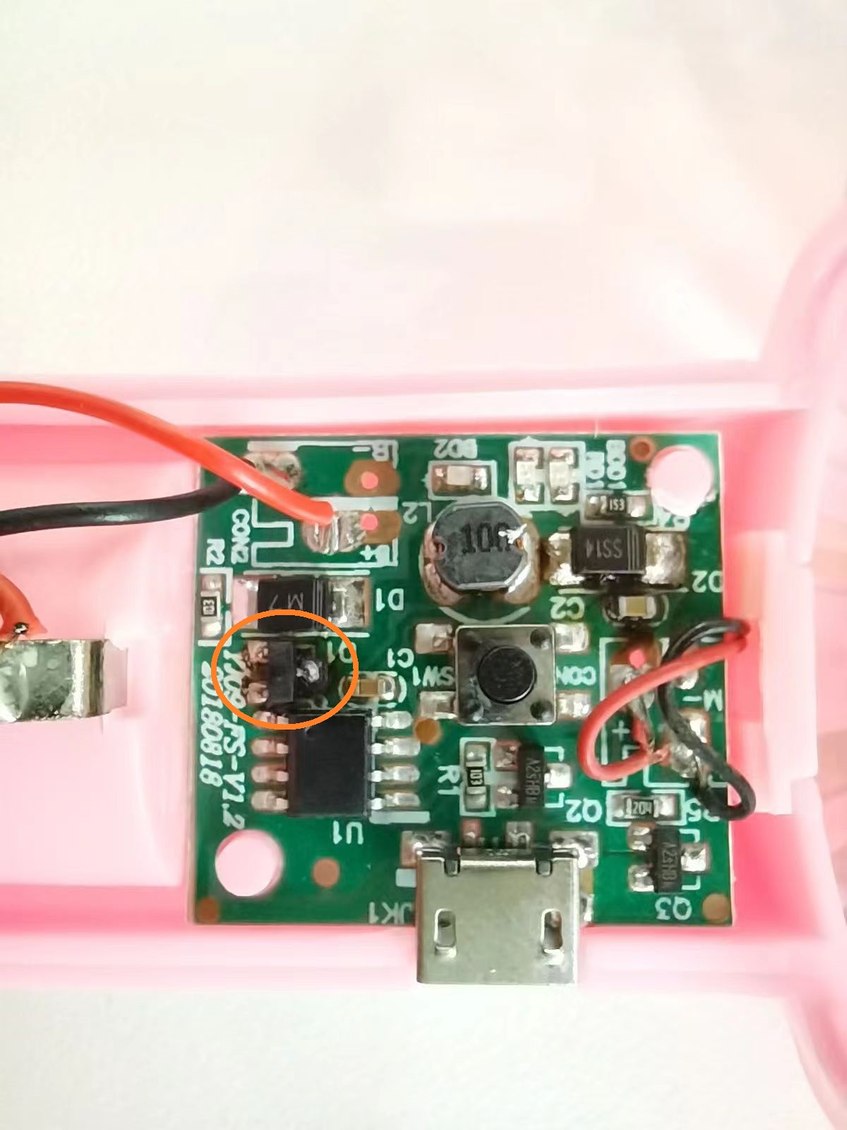
So, I decided to make a reliable control board myself using a cheap FM5010 chip. However, the first version was not only double-sided surface mount, but also had significant dimensional deviations, and it malfunctioned after a period of use, unable to control the fan's start and stop. Therefore, the fan was discarded and ended up in the electronic waste pile.
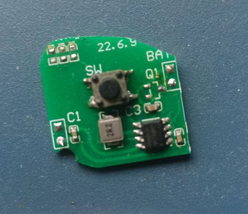
Two years later, using the same chip solution, I redesigned the driver board, and this time it was successful. The discarded fan was put back into use.

Project Introduction:
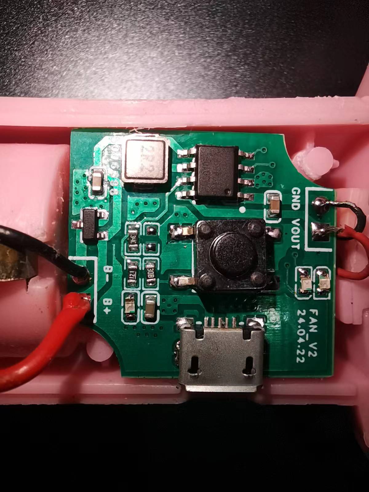
This project uses a 3.7V 18650 battery for power and uses a common portable fan casing, motor, and fan blades.
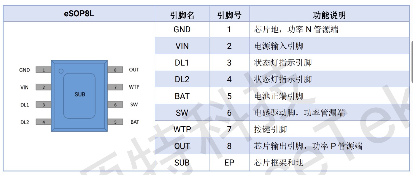
This project is based on the FM5010F chip. This chip is an integrated power IC for portable fans, integrating lithium battery charging management, three voltage output levels, and LED indicators for response status. The FM5010F discharges to drive the fan at output voltages of 4.7V, 5.5V, and 6.5V. The FM5010F features multiple protection designs, including overcurrent protection, soft-start protection, input overvoltage protection, output short-circuit protection, and chip temperature protection. It also incorporates high-performance ESD protection circuitry at the chip ports, ensuring high reliability. Therefore, the FM5010F meets the basic requirements of this project: driving the fan motor and providing multiple safety protection mechanisms to prevent malfunctions.
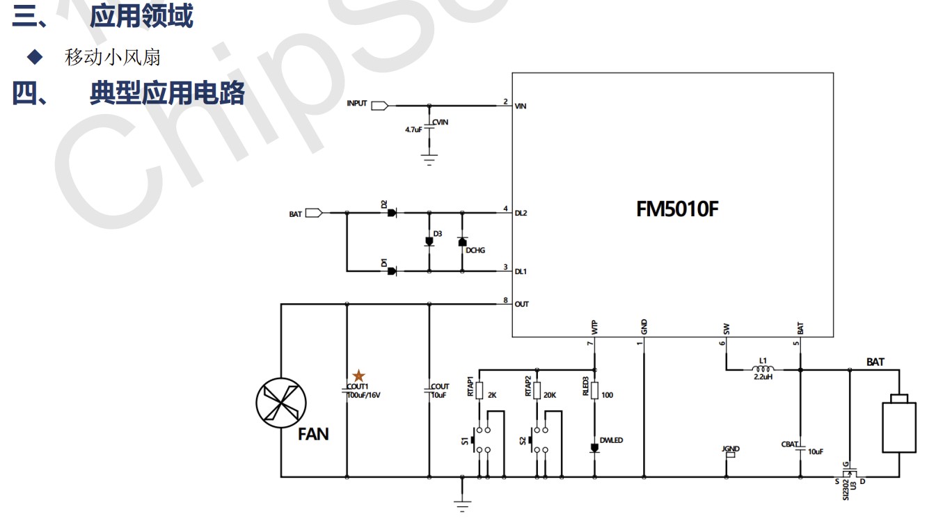
The FM5010F pin definitions and typical application circuit are as follows:
In actual use, the default function state and 2-LED display mode are adopted to simplify circuit design, reduce component costs, and shorten soldering time.


Precautions:
0. Please pay attention to the positive and negative terminals of the motor and battery during soldering!
The resistors RTAP2 and NC in the schematic diagram do not need to be soldered.
During normal operation, the indicator lights on the control board will flash.
The USB port is slightly misaligned, so directly charging the 18650 battery using this driver board is not recommended. It's suggested to use a dedicated charger instead.
The inability to achieve single-sided board wiring makes this project's cost somewhat high...


 京公网安备 11010802033920号

 PSD813F2V-12J


