① Voltage measurement + threshold judgment: the threshold level can be set according to requirements to meet different logic level scenarios, and retains the useful traffic light indication function of the "simple logic level test pen";
② Continuity measurement: the threshold resistance can be adjusted according to requirements;
③ Diode measurement: lights up a diode;
④ PWM output: provides a known quantity for system testing in some scenarios, and can also be used to test passive buzzers, etc.;
⑤ PWM input: can measure frequency;
⑥ DC output: simulates a required DC level for testing.
0916906dbe0d848aebdb2ae302377eb.jpg
PDF_Multifunctional Test Pen.zip
Altium Multi-functional Test Pen.zip
PADS_Multifunctional Test Pen.zip
BOM_Multifunctional Testing Pen.xlsx
97051
STM32 Oscilloscope
STM32 Oscilloscope - Open Source Project for Oscilloscope Expansion Boards Based on AFE03
Project Functions:
Dual-channel signal measurement: This oscilloscope can simultaneously measure signals from two channels, allowing for simultaneous observation and analysis of two different signals.
Internal DAC output: The oscilloscope features an internal DAC (digital-to-analog converter) that can output a single signal. The DAC's output range is 0-3.3V. This allows the oscilloscope to be used not only as a tool for observing and analyzing signals but also as a signal generator.
Use of expensive op-amp chips: To improve accuracy, this project uses expensive op-amp chips from TI (Texas Instruments). Operational amplifiers play a crucial role in many electronic systems, amplifying and modulating signals. Using high-quality op-amp chips improves measurement accuracy and stability.
PDF_STM32 Oscilloscope.zip
Altium_STM32 Oscilloscope.zip
PADS_STM32 Oscilloscope.zip
BOM_STM32 Oscilloscope.xlsx
97052
VGA signal generator
The VGA signal generator produces seven pure color signals for screen testing.
VGA Signal Generator - Early Version
(More features will be added gradually)
Update Log
2023/11/21 Updated V0_2:
Modified to use a timer to generate the vertical sync signal, avoiding errors in the vertical sync signal that cause some monitors to not recognize the correct resolution.
Added button support: M key to switch between automatic/manual mode; up and down keys to change the displayed solid color image.
IRC frequency modified to 25.175MHz.
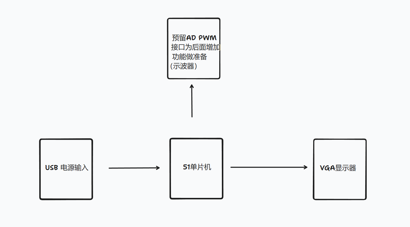
Note: Overall design scheme block diagram:
Schematic design description:
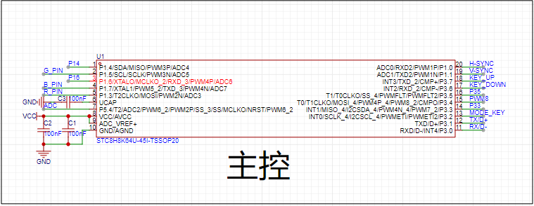
The main controller uses a cheap
and easy-to-use STC8H8k64U (
later upgraded to STC32G12K128).
The pins of the two are fully compatible.
If you only want to implement a simple VGA signal generator, you can use the former.
The latter is for later advanced applications.
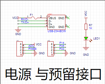
USB interface for convenient use with chargers, etc. Actual

test: R4, R5, and R6 do not need to be soldered. Monitors with a voltage greater than 0.7V will display the highest RGB color.
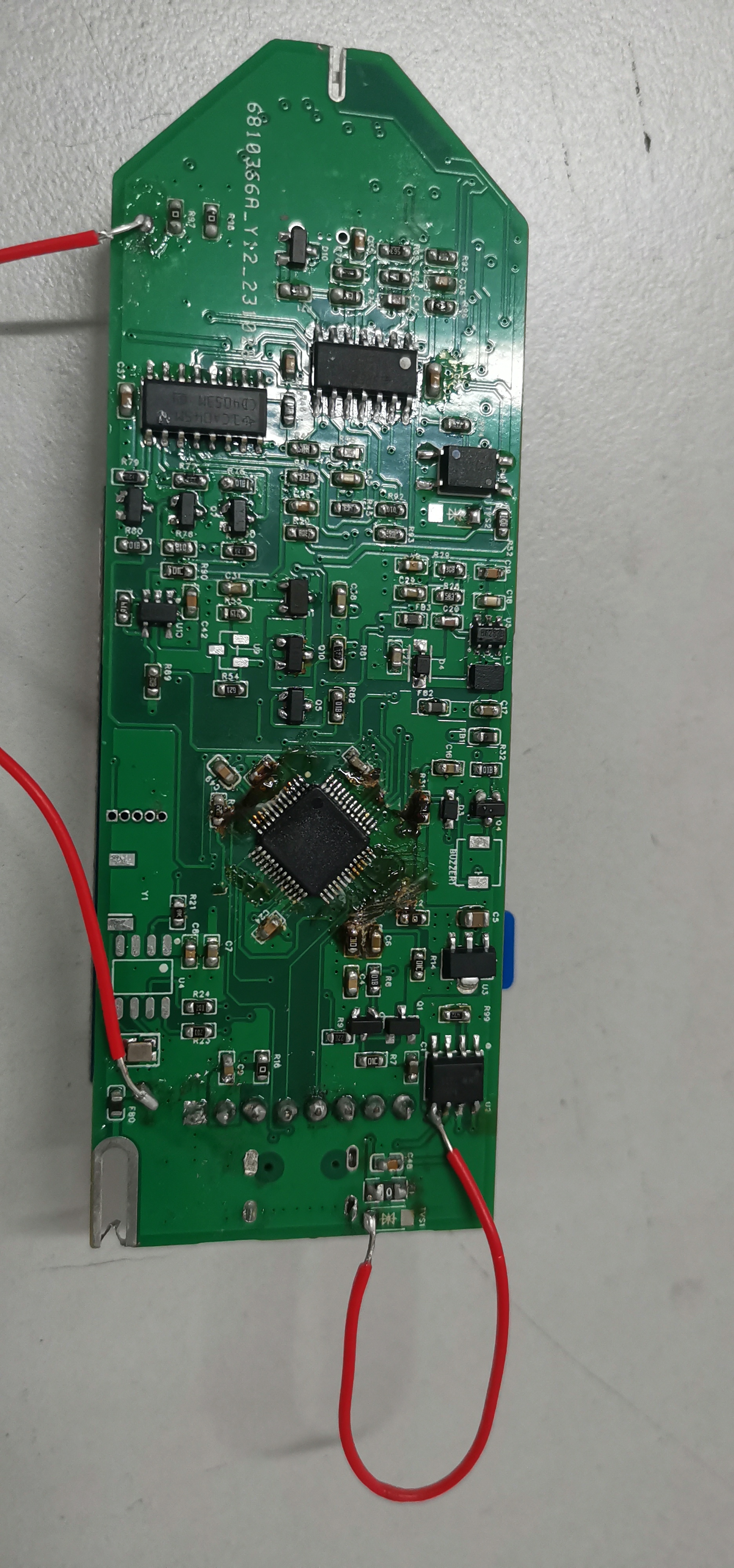
PCB design description:

Because I have an STC-USB LINK1D tool, I did not reserve a power switch.
If you do not have a similar tool, you need to add a switch, otherwise it will be difficult to burn
the software. Description:
PWM 1P generation Horizontal synchronization signal. The RGB signal 2N 3N 4N used for testing changes color every 1000ms during task scheduling (implemented by switching 2N 3N 4N).
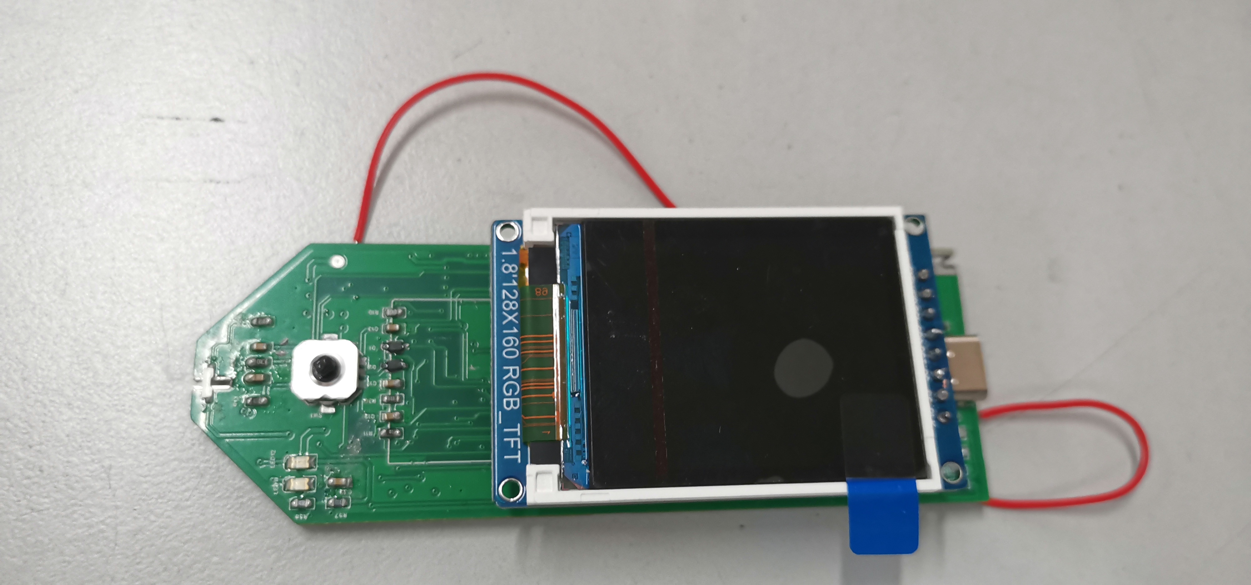
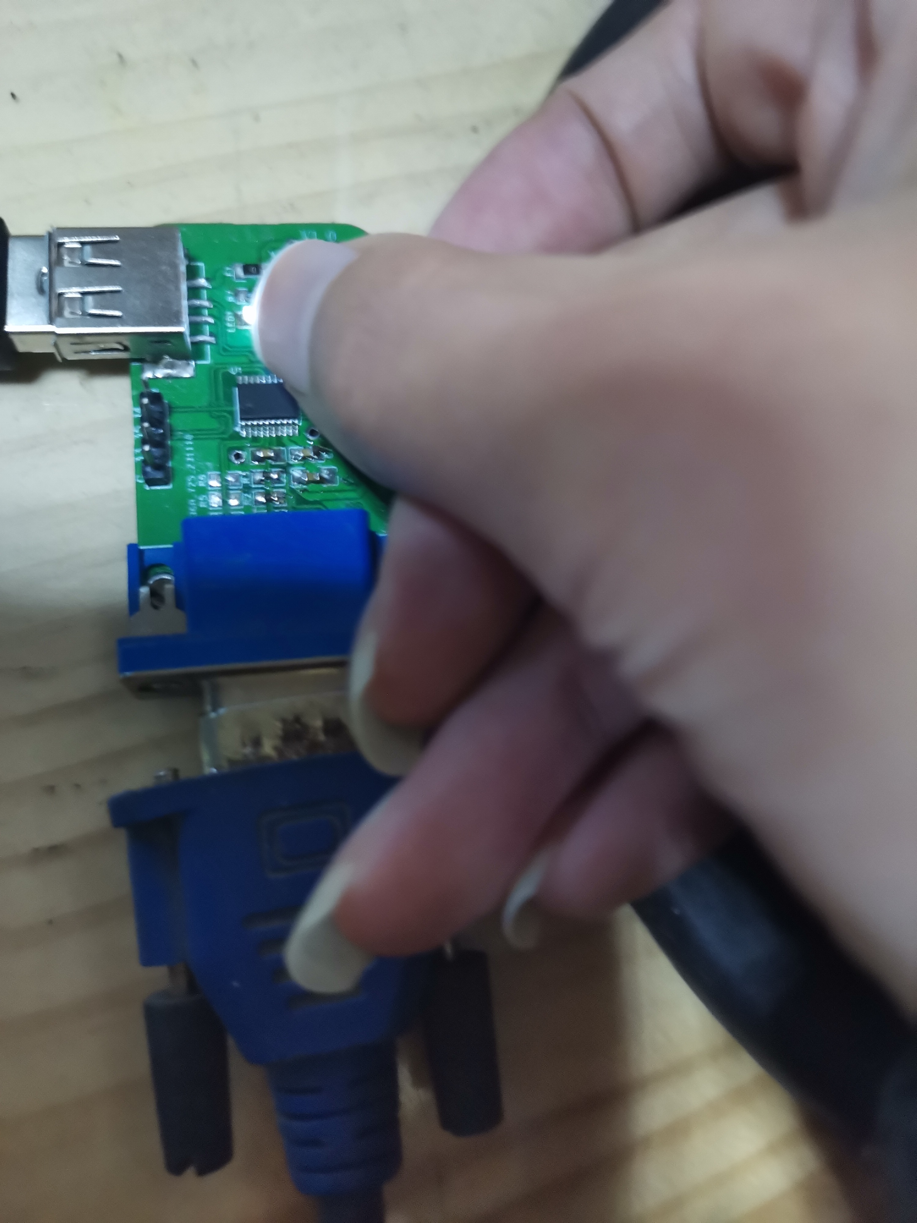
Physical demonstration: Outputting a solid color close-up high-definition image

via VGA. The LED has a cold solder joint; it only lights up when pressed. (´・ω・) Notes: Demonstration video (breadboard version)

(32G)VGA_V0_2.hex
32G_VGA V0.2.7z
PDF_VGA signal generator.zip
Altium_VGA signal generator.zip
PADS_VGA signal generator.zip
BOM_VGA signal generator.xlsx
97053
electronic


 京公网安备 11010802033920号

 DTR-1250-SM-GB-H8-C550-I


