Background:
When upgrading my smart home system, I discovered that the only pre-installed network cable on the ceiling was insufficient.
I have surveillance cameras and a smart home gateway,
so I needed to split one network port into multiple PoE power supply ports.
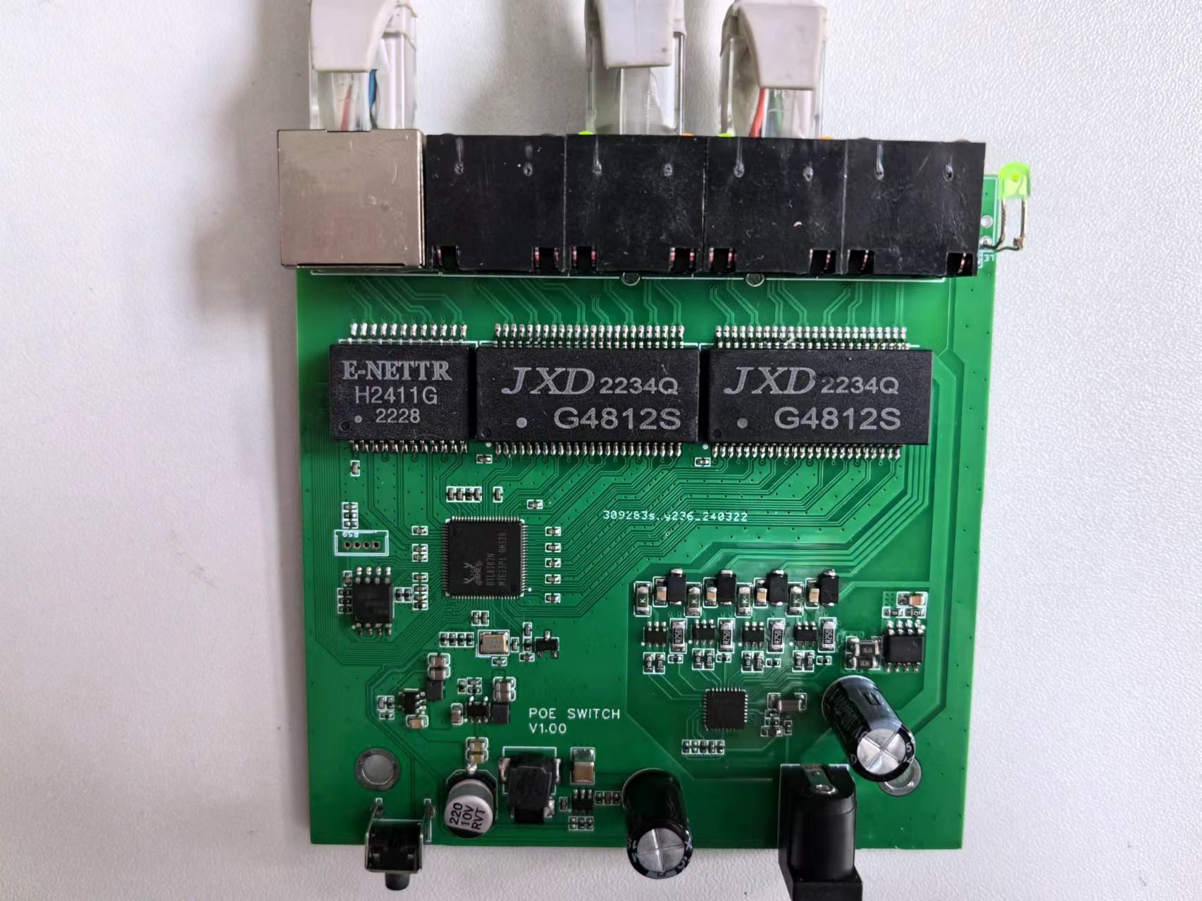
Therefore, I built a PoE power receiving and supply integrated (cascaded) gigabit switch.
Considering that my surveillance cameras and smart home devices are on different VLANs, this design supports VLAN management. I
designed a casing on the LCSC EDA, but unfortunately, I'm not good at structural design, so it's just a makeshift solution. Please don't criticize me, structural experts.
I have to complain about the LCSC EDA here: firstly, some packages have problems, so you must check them carefully during the design process; secondly, it's very laggy. It doesn't have the smooth feel of Alibaba's EDA.
Error correction: Do not use the part number shown in the schematic for the varistor RV1. You need to choose one with a higher operating voltage. I actually used TVM5B820K601RY, and you can choose a similar model from the LCSC online store. If it's for home use, you can omit the varistor and TVS.
The design scheme
uses the commonly used RTL8367N switching chip, which is very inexpensive on Taobao. Any
Flash chip with 16Mb or higher can be used.
The PD chip is the XS2100S, supporting 30W at standard power supply. (SD4923, TPS2378, etc. are also options.)
The PSE chip is the MAX5980GT, supporting 4-channel at standard power supply; the main peripherals are simple and can be hardware controlled. (Very inexpensive on Taobao.) For
the switch section's power supply, the 48V to 5V buck converter uses the TD1466, and the two power supplies for the RTL both use the SY8088.
The entire board's PoE power supply section uses the 30W at standard, with all four power ports providing at standard output support (of course, the total power cannot exceed this). I connected three IPC cameras and a Xiaomi central gateway downstream, and the power supply was sufficient (less than 10 watts).
20240402: Added version V1.10, which adds a maximum power alarm; when the output reaches the maximum power under the at standard power supply, the indicator light will illuminate.
20240422: Added version V1.20. This version modifies version V1.00 to use BT standard class 8 power supply, i.e., BT 90W power supply.
Debugging and testing:
1. The MAC address and serial number need to be modified manually. The default MAC address and serial number are: CC:CC:CC:CC:CC:CC and 3MX8888888D8. Modify the address to 0x001FC000.
2. The RTL chip gets extremely hot after enabling the MCU. Pay attention to heat dissipation.
3. There are several heat sources on the board that need attention: RTL chip, rectifier bridge, PD chip, and high-voltage buck.
4. This design does not use a PoE dedicated network transformer; I used a regular one. If you need to replace it, you can choose one with the same package.
5. The network cable is strictly differential and not designed for equal length and impedance. If needed, calculate the impedance and fine-tune it yourself.
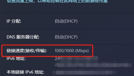
6. One lit network port indicator light indicates 10M/100M, two lit lights indicate 1000M.
7. Default login address: 192.168.0.239
8. Long press the button to initialize.


MAX5980GTJ+T.PDF
XS2100S.PDF
PDF_5-Port PoE Powered Managed Gigabit Switch - RTL8367N.zip
Altium 5-Port PoE Powered Managed Gigabit Switch - RTL8367N.zip
PADS 5-Port PoE Powered Managed Gigabit Switch - RTL8367N.zip
BOM_5-Port PoE Powered Managed Gigabit Switch - RTL8367N.xlsx
94300
Multifunctional Tester Based on STM32
Simple multi-functional tester:
Uses INA226 for current and voltage parameter acquisition;
utilizes the STM32 built-in ADC for resistance measurement;
and employs MAX6675 and type K thermocouples.
Supports serial port data upload.
The schematic design describes
the acquisition of voltage and current signals using an INA226 microcontroller.

Temperature is acquired using a MAX6675 microcontroller and a K-type thermocouple.

The software
cyclically prints the acquired parameters, and users can select data to upload to the serial port via buttons.
Code block:
int main(void)
{
uint16_t cur,temp;
// Clock initialization
SysTick_Init();
uart_init(115200);
// Screen initialization
TFT_Init();
// ADC initialization
Adc_Init();
// INA226 initialization
INA226_Init();
// MAX6675 initialization
MAX6675_Init();
// Key pin initialization
Init_Key_GPIO();
// Fill black
TFT_Fill(0,0,160,128,BLACK);
// Initialize static UI
TFT_StaticUI(&TestTools);
while(1)
{
// Key scan processing function
Key_Handle(&TestTools);
// Parameter display UI
TFT_ShowUI(&TestTools);
TestTools.InaVoltage=INA226_GetVoltage(WRITE_ADDR)/8;
cur = INA226_GetShuntCurrent(WRITE_ADDR); // Get current value
if(cur&0x8000)cur = ~(cur - 1); // Negative current // Because the negative terminal needs to be grounded, reverse current measurement is not allowed. Negative values are actually not allowed.
TestTools.InaCurrent=cur;
TestTools.ResAdcValue=Get_Adc(4);//Get the resistance measurement ADC value
TestTools.BatAdcValue=Get_Adc(2);//Get the battery charge ADC value
temp=readMAX6675();
TestTools.TempConnection=temp&0x4;//0x4 is disconnected, 0 is connected to the thermocouple
temp= temp<<1;//Get bits 3~14
temp= temp>>4;
TestTools.temperature=temp;
if(TestTools.showmode==1)
printf("Voltage:%.2f
",TestTools.InaVoltage/100.0f);
if(TestTools.showmode==2)
printf("Current:%.3f
",TestTools.InaCurrent/1000.0f);
if(TestTools.showmode==3)
printf("Temperature:%.1f
",TestTools.temperature*0.25f);
delay_ms(300);
}
}
Physical demonstration instructions
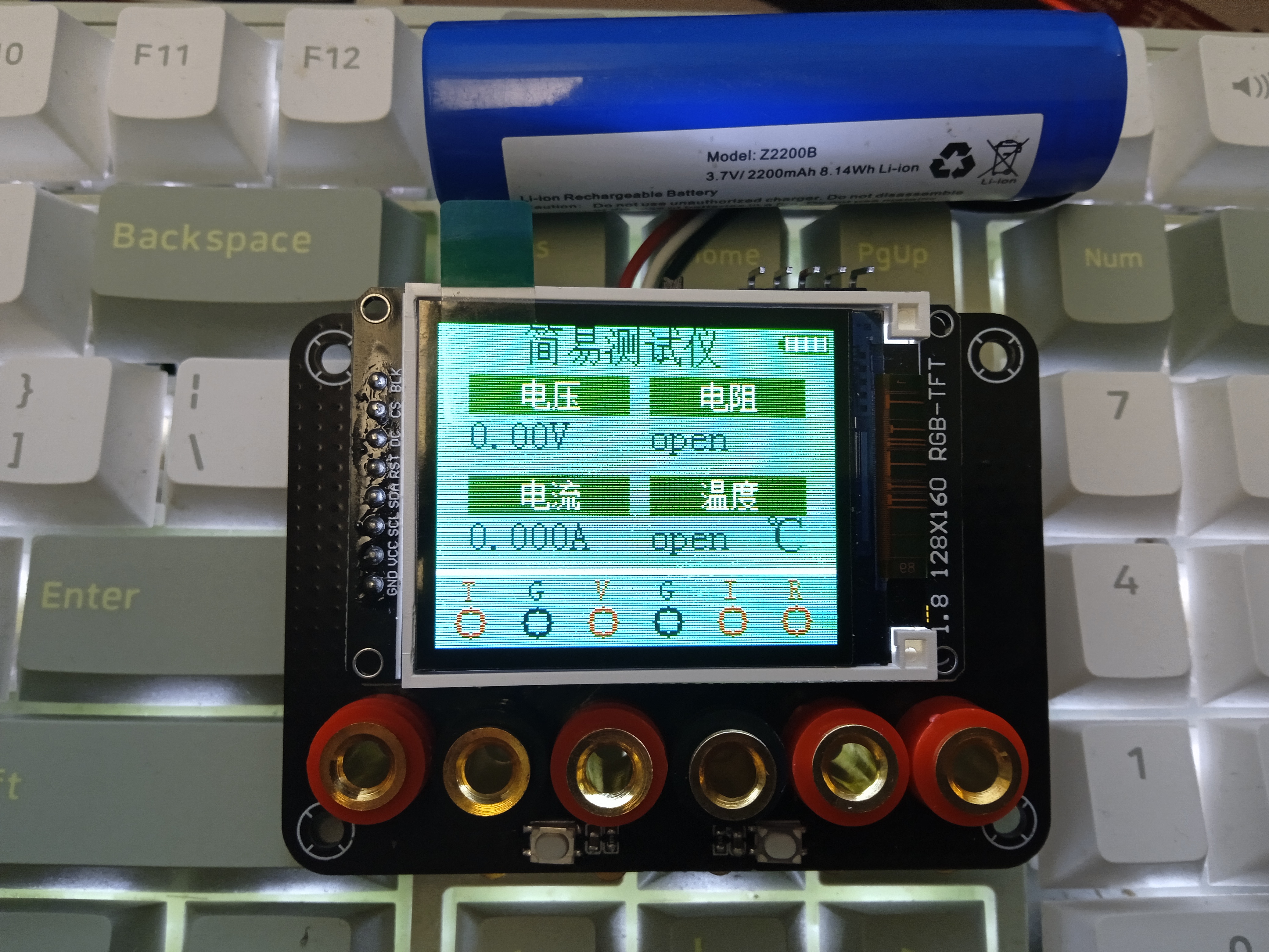
and precautions
: Note that the battery is a single lithium battery.
Demonstration video
: https://space.bilibili.com/35559163?spm_id_from=333.1007.0.0
TEST_TOOL.7z
PDF_STM32-based Multifunctional Tester.zip
Altium_STM32-based Multifunctional Tester.zip
PADS_STM32-based Multifunctional Tester.zip
BOM_STM32-based Multifunctional Tester.xlsx
94301
Bluetooth controller
Bluetooth controller
This controller uses an STM32F103C8T6 chip and Bluetooth communication.
The
charging module uses a TP4056 chip for battery management, offering the following advantages:
• Programmable charging current up to 1000mA •
No MOSFET, sense resistor, or isolation diode required
• Complete linear charger for single-cell lithium-ion batteries in an SOP package
• Constant current/constant voltage operation with thermal regulation to maximize charging rate without overheating
• 4.2V preset charging voltage accuracy up to ±1.5%
• Charging current monitor output for battery level detection
• Automatic recharging
• Dual outputs for charging status, with no battery and fault status indicators
• C/10 charging termination
• 55uA supply current in standby mode
• 2.9V trickle charging device version
• Soft-start limits inrush current
• Battery temperature monitoring function
• 8-pin SOP-PP package.
The charging current can be adjusted by changing the resistor R13 in the above schematic diagram.
II.
The joystick uses an ADC for data acquisition:
the joystick is a bidirectional cross 10K resistor. The module uses 5V power supply. In its original state, the X and Y read voltages are approximately 2.5V. When the joystick is pushed in a certain direction, the corresponding axis voltage value increases or decreases, with a maximum value of 5V and a minimum value of 0V.
1. Operating voltage: 5V
2. Output voltage range: 0~5V
3. Interface: Two analog signals represent X and Y offsets, and one digital signal SW represents whether the Z-axis is pressed.
III.
Buttons are controlled by detecting high and low levels using ordinary I/O ports.
IV.
The OLED uses a four-interface I/O protocol to write and display the required data,
enabling wireless control of the car.
It is suitable for beginners and is simple and easy to use.
PDF_Bluetooth controller.zip
Altium Bluetooth controller.zip
PADS Bluetooth controller.zip
BOM_Bluetooth controller.xlsx
94302
ESP32 Reflow Oven - Control Board V2
I've replicated the "Super Basic ESP32 Heating Stand V2" from this site (https://oshwhub.com/false0/esp32-jia-re-tai_copy), and made some modifications based on my own inventory.
I've replicated the "Super Simple ESP32 Heating Platform V2"
(https://oshwhub.com/false0/esp32-jia-re-tai_copy) from this site, making some modifications based on my own inventory.
Project address: https://github.com/652626737/kk-heater-reflow-soldering
PDF_ESP32 Reflow Oven - Control Board V2.zip
Altium_ESP32 Reflow Oven - Control Board V2.zip
PADS_ESP32 Reflow Oven - Control Board V2.zip
BOM_ESP32 Reflow Oven - Control Board V2.xlsx
94305
[Verified] STM32F103C8T6 Minimum System Board
This is a homemade small board for the STM32F103C8T6. It's small in size and can be fired on a single-sided iron plate in one go. The pinout is a 1:1 replica of the common small blue boards on the market.
![WeChat image_20240611195146.jpg]

A homemade STM32F103C8T6 mini-board. All components are arranged on only one side of the board, allowing for single-sided baking. All pins are brought out one-to-one with common small blue boards on the market, but because it is too wide, it cannot be inserted into a breadboard QAQ.
The board uses a CH340C serial port to USB chip (you can also replace it with CH340N or other models to save space). It also has indicator lights to make it easy to check the transmission status. In addition to the onboard peripherals, there is a button on PA0 (WKUP) and an LED on PC12.
The board uses ST-Link as the primary download method and provides relevant interfaces, but also includes a BOOT button, theoretically supporting serial port program download (the author has not verified this due to infrequent use).
***Note that the LED resistor values in the schematic are for reference only. I personally believe the brightness is very low; please determine the specific resistance value according to your brightness requirements. Around 1KΩ is recommended. Furthermore, the BOM (Bill of Materials) is only for reference; exporting the BOM for ordering is not recommended.***
The board was designed by myself. I welcome any criticism and suggestions for improvement
! [WeChat image_20240611194738.jpg]

The 1.3-inch OLED screen in the image is from another project: https://oshwhub.com/maker114/1-3-cun-oled
PDF_【Verified】STM32F103C8T6 Minimum System Board.zip
Altium_【Verified】STM32F103C8T6 Minimum System Board.zip
PADS_【Verified】STM32F103C8T6 Minimum System Board.zip
BOM_【Verified】STM32F103C8T6 Minimum System Board.xlsx
94306
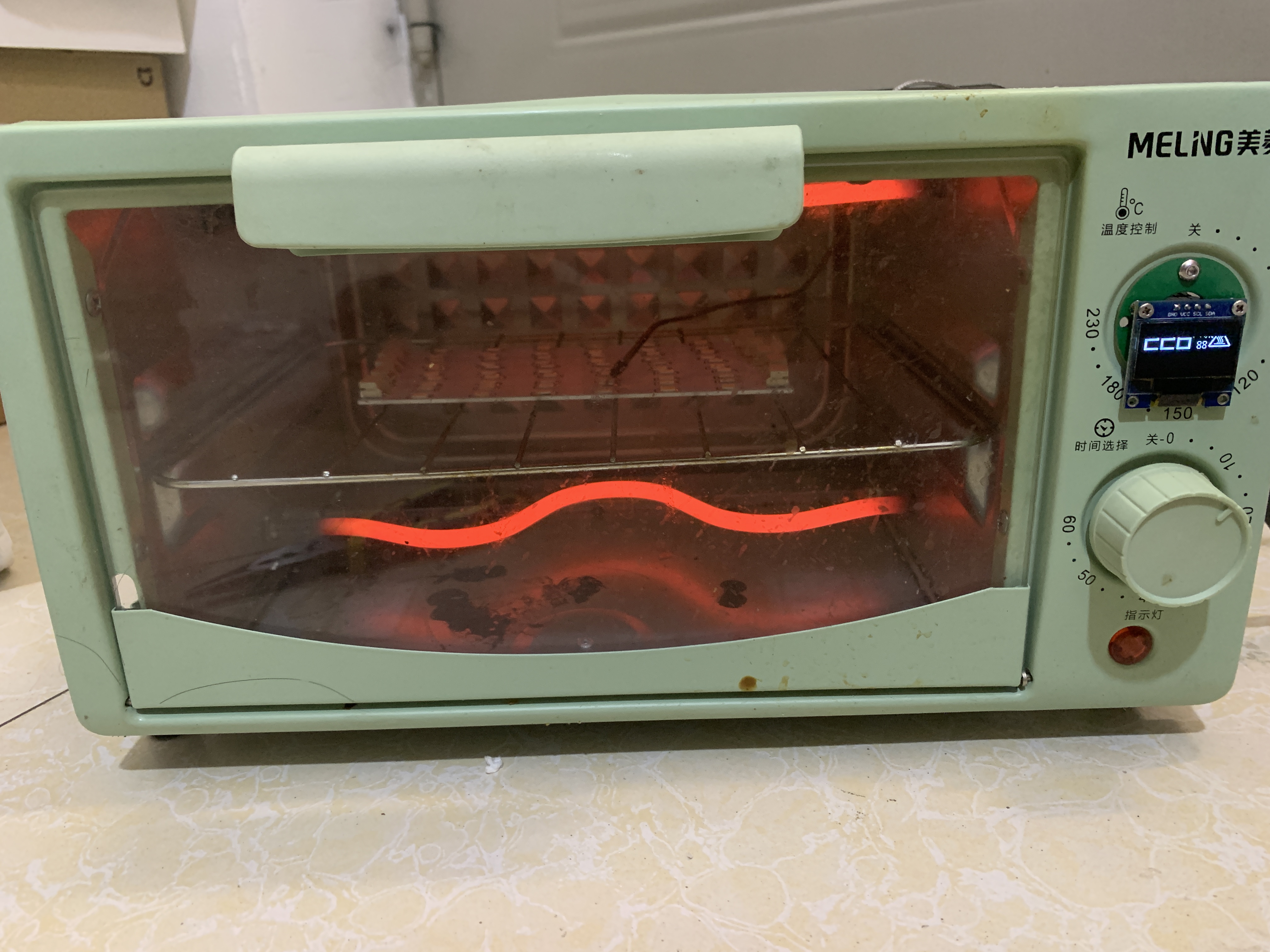
ESP humidifier
The humidifier uses a 555 motor and is controlled by an ESP-12S controller.
I. Humidifier Design
The humidifier uses an NE555 timer to generate a 108kHz square wave to drive the spray nozzles. Direct drive voltage is too low, so a boost circuit is used to increase the voltage. An ESP-12S control chip is added to enable IoT control of the humidifier. An AHT20 temperature and humidity sensor is used to detect ambient temperature and humidity.
II. Boost Circuit The
boost circuit consists of two parts:
a 12V boost circuit
and a MT3608 boost chip. The 12V boost circuit ensures the minimum operating voltage for the spray nozzles.
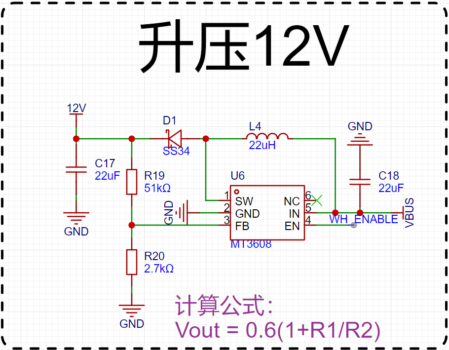
The output voltage depends on the ratio of two resistors, calculated according to the formula in the chip's datasheet. These two resistors were adjusted based on my existing resistors.
The boost circuit
is shown in the diagram below. The switching transistor controls the inductor's energy storage and release, resulting in a higher output voltage than the input voltage.

III. Frequency Generation Circuit A
555 timer is used to generate a 108kHz frequency. The output frequency calculation is shown in the diagram. Since I used existing components, and considering the accuracy of the capacitors, the actual output frequency needs to be tested to ensure it matches correctly.

IV. Non-contact Liquid Detection:
The TC301D is used for non-contact liquid detection. Pay attention to the PCB layout; specific details can be found in the datasheet.
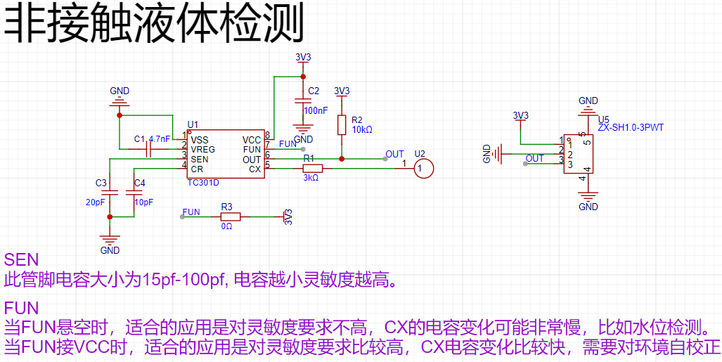
V. Shortcomings and Optimizations:
Because many components are readily available, the circuit power supply is insufficient. The inductors and capacitors in the boost circuit could be replaced with smaller ones. Non-contact liquid detection has not yet been verified.
IMG_6458.MP4
BOM_ESP Humidifier.xlsx
94308
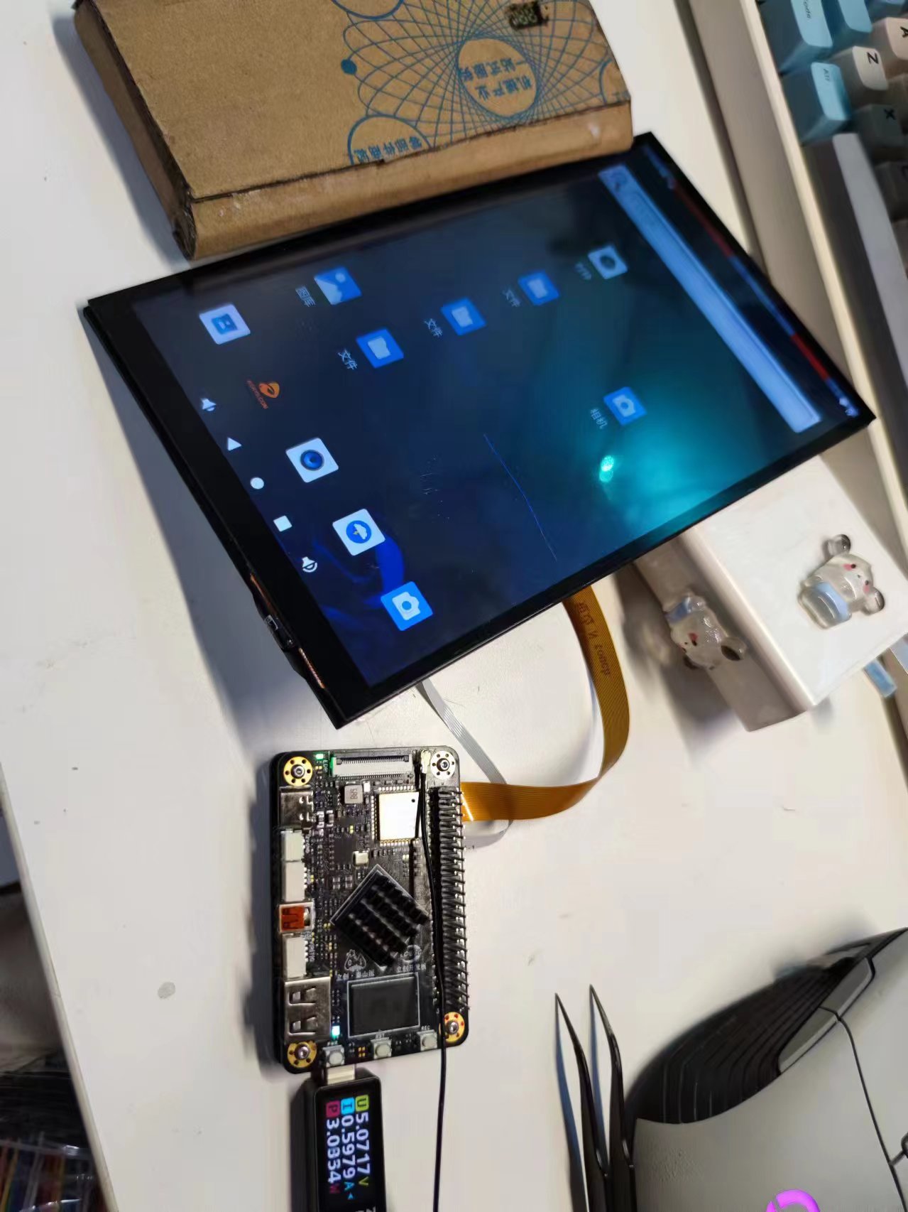
Smart small mobile phone
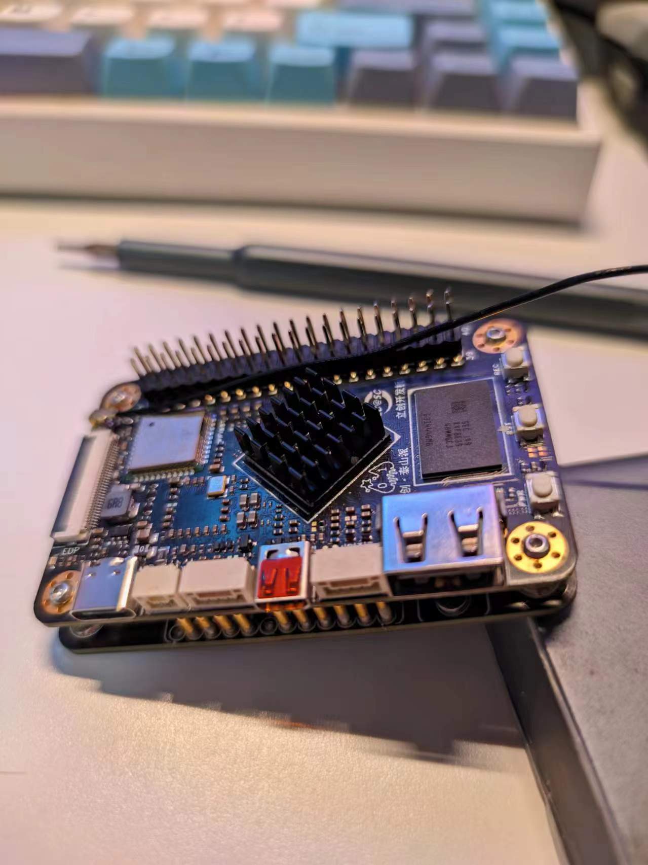
This is a small smart phone expansion board based on the Taishanpai platform. It features onboard USB-to-TTL conversion, battery charging, 5V-to-12V power supply, and automatic battery/USB switching circuitry. It also adapts the pin order of the Taishanpai's built-in MIPI and touch interfaces to a 3.1-inch touchscreen display.
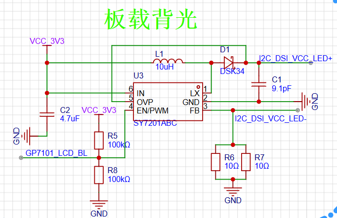
The IIC-to-PWM control of the screen backlight
extends from the touch IIC pin of the Taishanpai device, using a GP7101-F1K-L1H1-SW chip.
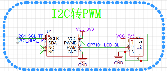
A SY7201ABC constant current source chip then converts the PWM signal into a constant current to drive the screen backlight.
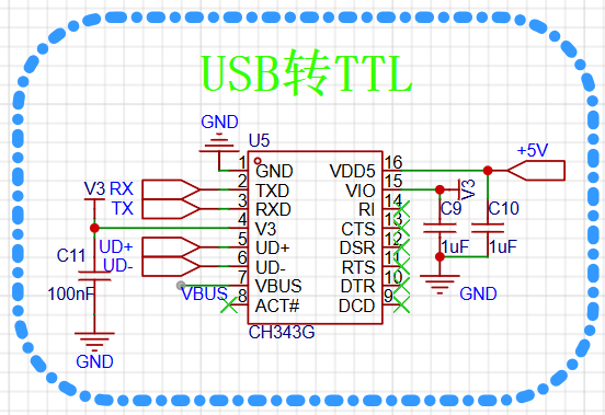
The Taishanpai device also has TTL contacts, enabling direct data communication with the computer via a USB-to-TTL converter.
The lithium battery management circuit
uses an IP5407 chip to build a lithium battery charging circuit,
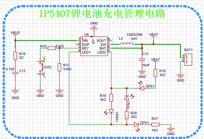
converting 5V USB voltage or 4.2V battery voltage to 12V to power the Taishanpai device.
A BOOST boost circuit using an MT3608 chip provides the 12V output. (Actual

product demonstration shown. )


PDF_Smartphone.zip
Altium_Smartphone.zip
PADS_Smart Mini Phone.zip
BOM_Smart Small Phone.xlsx
94309
electronic


 京公网安备 11010802033920号

 ZCS1-120A7DC6VC121


