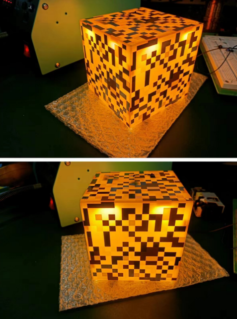
This project is based on @SMALL_DA's idea for a TNT ambient light, with some changes to the circuit, board shape, and splicing structure to create a small object that looks like a glowstone lamp from Minecraft.
I. Effect Demonstration

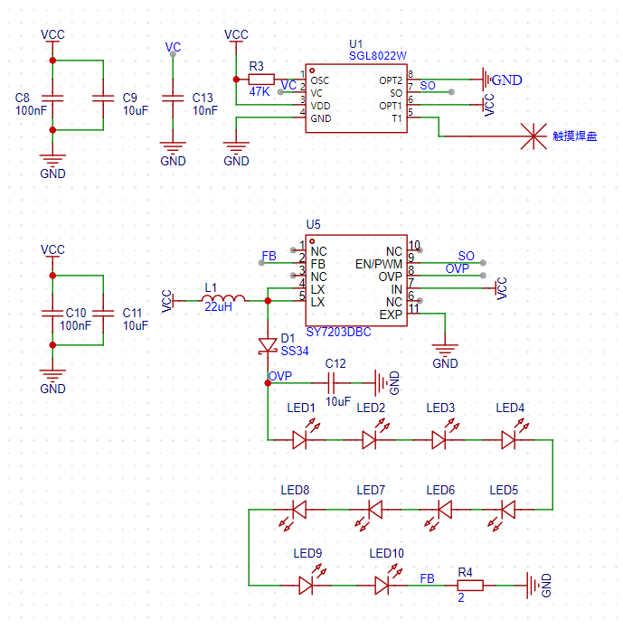
II. Circuit Introduction
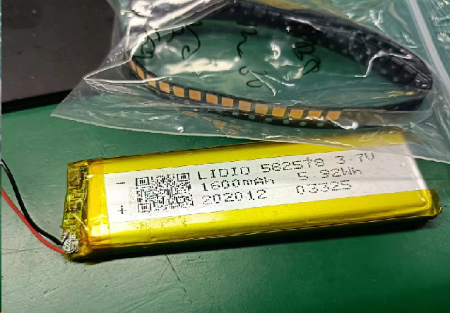
This part connects the charging/discharging module and the battery. When there is no external Type-C port, the battery powers the circuit board through the module and switch. When an external Type-C port is connected, it charges the battery while simultaneously powering the circuit board.

This part contains the touch chip and the DC-DC boost LED driver chip. After touching the pad, U1 outputs PWM to U5, thereby controlling the output of U5. For specific principles and resistor/capacitor parameter selection, please refer to the datasheets of these two chips.
C13 adjusts the touch sensitivity, and R4 modifies the LED current; I set the LED current to 100mA.
III. PCB
Fabrication Two PCBs are required. Both boards are 10cm*10cm and can be obtained for free through the JLCPCB order assistant with a coupon.
When placing an order, remember to include the customer code in the order notes at the bottom

. IV. Component Purchase
Components can be purchased from the LCPCB online store or Taobao. One important point to note is that the LED color must be warm white, packaged as 2835, 1W 3V.
The module was purchased from Taobao. The copper pillars and screws are used to fix the glowstone lamp to the top plate; you don't need to buy them if you don't need a mounting plate.
If you don't need battery power, you can skip buying batteries and use Type-C power directly. I used batteries from my own stock.

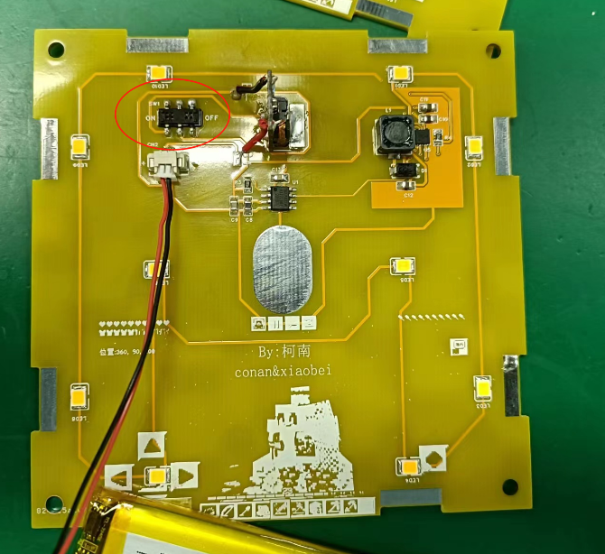
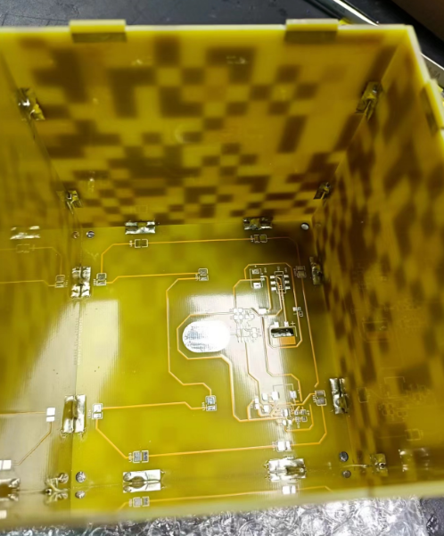
V. Soldering the Mainboard and Debugging
First, solder the mainboard and check for short circuits before powering it on. Lightly press the touch pads; the lamp will gradually light up. Long press the touch pads to adjust the brightness. Lightly press the touch pads again; the lamp will gradually turn off. (You can refer to the video below.)
Note that the switch is installed backwards; the top layer of the board can be used to toggle the switch, while the bottom layer is only for soldering.
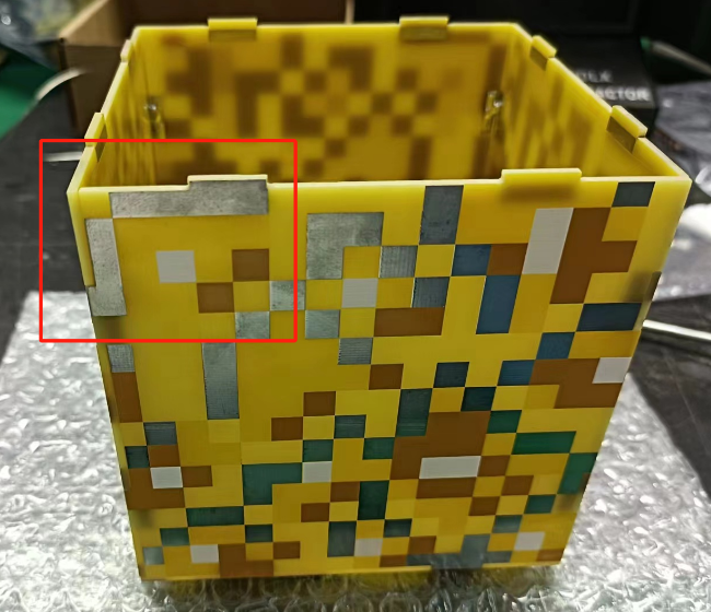
VI. Soldering the Board Frame
First, use one mainboard as the base of the glowstone lamp, then take a board frame and assemble it, fixing it with solder.
Note that when soldering, ensure the angle between the mainboard and the bottom board is approximately 90°, otherwise it won't look good. It is recommended to have a flat object on the back for support when soldering. (I used the side of the hot air gun stand for support.)

Secure each pad connection with solder.
Note: This marking should always be in the upper left or lower right corner, otherwise the board splicing interface will not align.
Repeat four times, then you can place the soldered motherboard on to test the effect.
VII. Board Fixing
If you have copper pillars and screws, and have completed the above operations, you can start fixing the board. For the fluorite lamp, one screw connects to the bottom to the inside, which is then connected with copper pillars. The top is then connected to the inside with another screw.
For battery fixing, simply fix the battery to the bottom.

VIII. Additional Notes
1. Because there is no copper plating on the top layer, the boost chip has no place to dissipate heat, so the LED brightness should not be kept at maximum all the time, otherwise the chip will overheat significantly.
Using an LM2596 5.0 to step down from 24V to 5V, and using an LDO to step down to 3.3V.
Using an LM2596 5.0 to step down from 24V to 5V, and using an LDO to step down to 3.3V.

PDF_LM2596 power supply circuit.zip
Altium_LM2596 power supply circuit.zip
PADS_LM2596 power supply circuit.zip
BOM_LM2596 Power Supply Circuit.xlsx
94319
AD8099 High-speed op-amp
High-speed amplifier circuit based on AD8099
A high-speed amplifier circuit with 10x gain built using AD8099
has been verified. At 100MHz, it can amplify a 100mV peak-to-peak sine wave to approximately 900mV.
Single-sided routing is convenient for manual PCB fabrication.
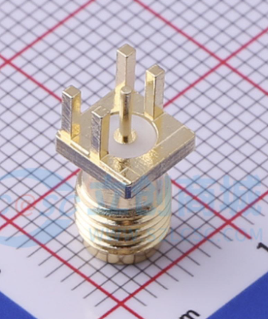
Note: The SMA interface should be BWSMA-KE-PO01 (searchable on LCSC).
AD8099 chip introduction: Ultra-low distortion, high speed, 0.95NV/√Hz voltage noise operational amplifier; at a gain of 10, bandwidth up to 550MHz, slew rate up to 1350V/µs.
AD8099 High-Speed Operational Amplifier_2024-06-10.epro
PDF_AD8099 High-Speed Op-Amplifier.zip
Altium_AD8099 high-speed op-amp.zip
PADS_AD8099 High-Speed Operational Amplifier.zip
BOM_AD8099 High-Speed Op-Amplifier.xlsx
94320
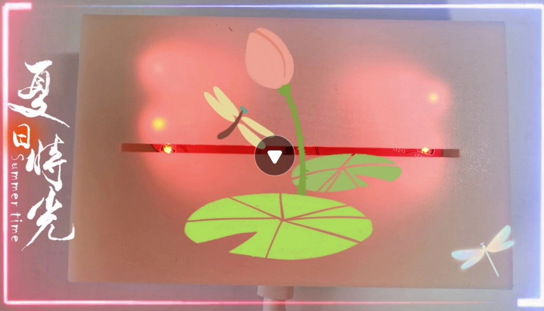
Summer Dragonflies
The spring flows silently, its gentle stream cherished; the shade of the trees reflects on the water, loving the soft sunshine. A tiny lotus bud just begins to emerge, and a dragonfly has already alighted on it. Create a summer dragonfly LED light.
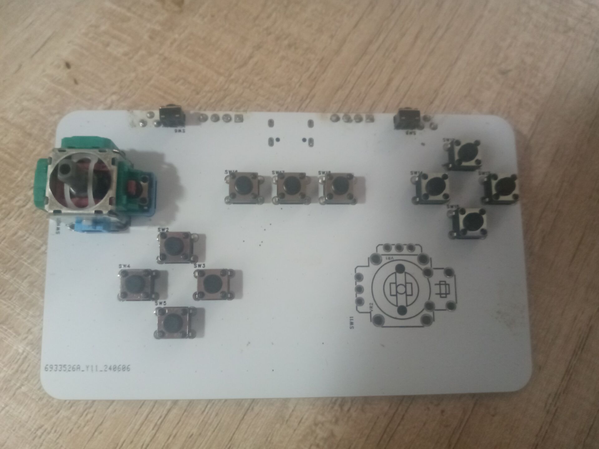
The spring flows silently, its gentle stream cherished; the shade of the trees reflects on the water, loving the soft sunshine. A tiny lotus bud just begins to emerge, and a dragonfly has already alighted on it. Create a summer dragonfly LED light. Control the different flashing effects of the LED light using buttons.

petal_20240530_234533.mp4
PDF_Summer Dragonfly.zip
Altium_SummerDragonfly.zip
PADS_Summer Dragonfly.zip
BOM_Summer Dragonfly.xlsx
94321
electronic


 京公网安备 11010802033920号

 GB19264ESYAAMUA-V00


