I. Introduction
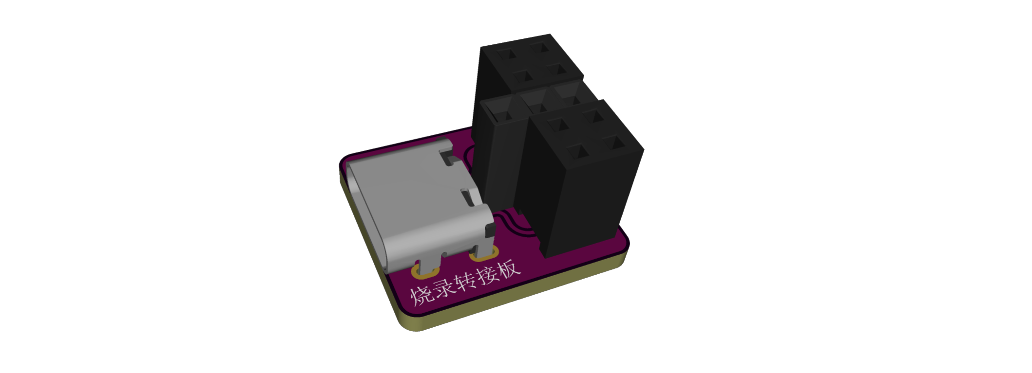
* This design utilizes SBU1 and SBU2 of a Type-C interface, which are multiplexed as SWCLK and SWDIO download interfaces respectively, such as in the iDKMeter02C
. * The middle GND has three rows of anti-reverse connectors; either 2 (2x2) + 1 (1x3) or 1 (1x5) + 3 (1x2) female connectors are acceptable
. * The male connector of the clamp has a correct orientation when inserted; only one side can be programmed
. * Due to its small size, it is somewhat awkward to use; I will modify it when I have time.
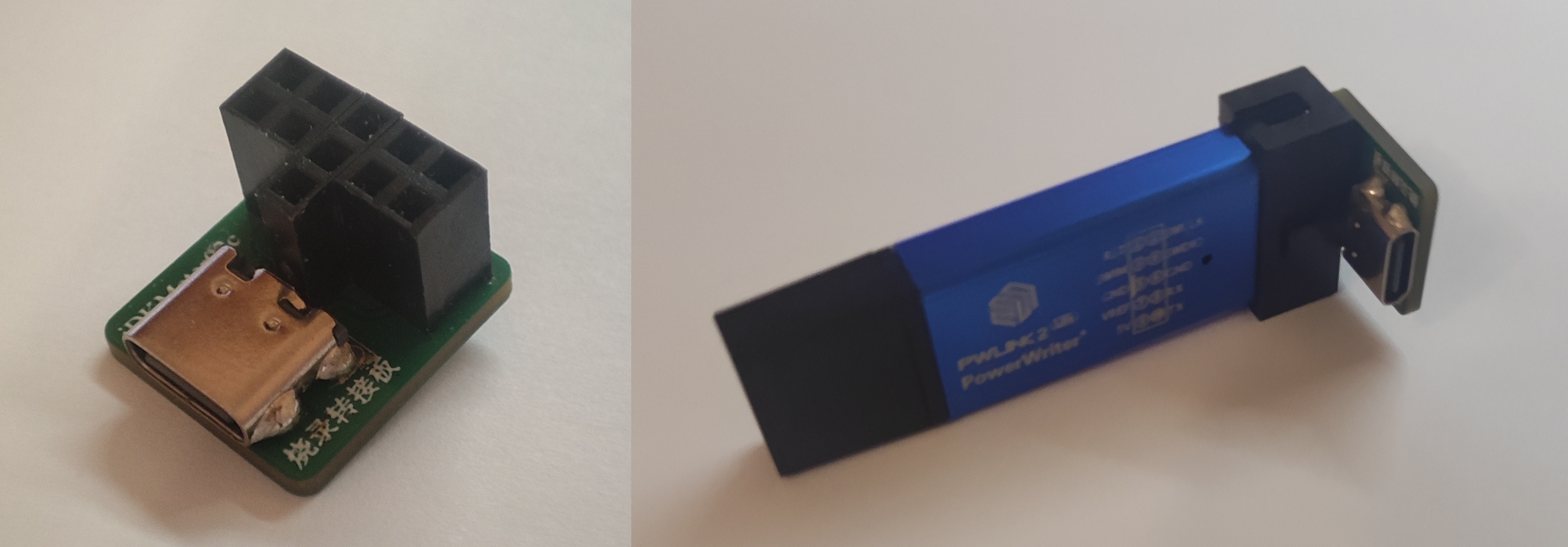
II. Display Diagram
PDF_PWLINK Burning Adapter Board.zip
Altium_PWLINK programming adapter board.zip
PADS_PWLINK programming adapter board.zip
BOM_PWLINK Programming Adapter Board.xlsx
94424
Direct power connection night light design
Direct power connection night light design
The night light connects directly to the power supply via a power cord, ensuring a stable power supply. It uses LEDs (light-emitting diodes) as the light source, which are highly efficient, energy-saving, and have a long lifespan. LEDs provide soft light, suitable for nighttime use. The LEDs are connected to the DC power supply circuit, and a resistor limits the current, ensuring normal operation and extending the LED's lifespan. A manual control switch is included, allowing users to easily turn the night light on or off as needed.
PDF_Design for a Direct-Connected Night Light.zip
Altium_Power Direct Connection Night Light Design.zip
PADS_Power Direct Connection Night Light Design.zip
BOM_Direct Power Connection Night Light Design.xlsx
94425
DIY PCB Electronic Musical Instrument - Cardboard Electronic Keyboard for 5 Dollars!
This is an 8-key style electronic keyboard with capacitive touch keys. The entire project requires only 9 parts to assemble – simple and convenient! PCB prototyping is free, and the cost of other materials will not exceed 5 yuan. (The Atmega 328p is reusable and not included in this calculation.)
QQ Group for Discussion: 571521559
This time, I'm sharing a new electronic musical instrument project:

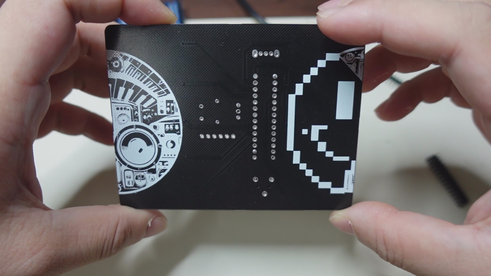
• It's called "Card Stylophone" because its main body is a PCB board, looking just like a card, and it has similar gameplay to a stylophone.
• This project doesn't use complex analog circuits like 555 timers or oscillators; instead, it's all implemented through firmware code, significantly reducing the number of components that need to be soldered.
• To exaggerate a bit, Card Stylophone is a "minimum viable product," aiming to minimize the time from starting the kit to creating music with it.
Okay, let's start practicing the production steps and relive the 80s style of electronic music! :)
(Best enjoyed with the video below!)
↓↓↓
https://www.bilibili.com/video/BV1UJ4m137x1/
STEP 1:
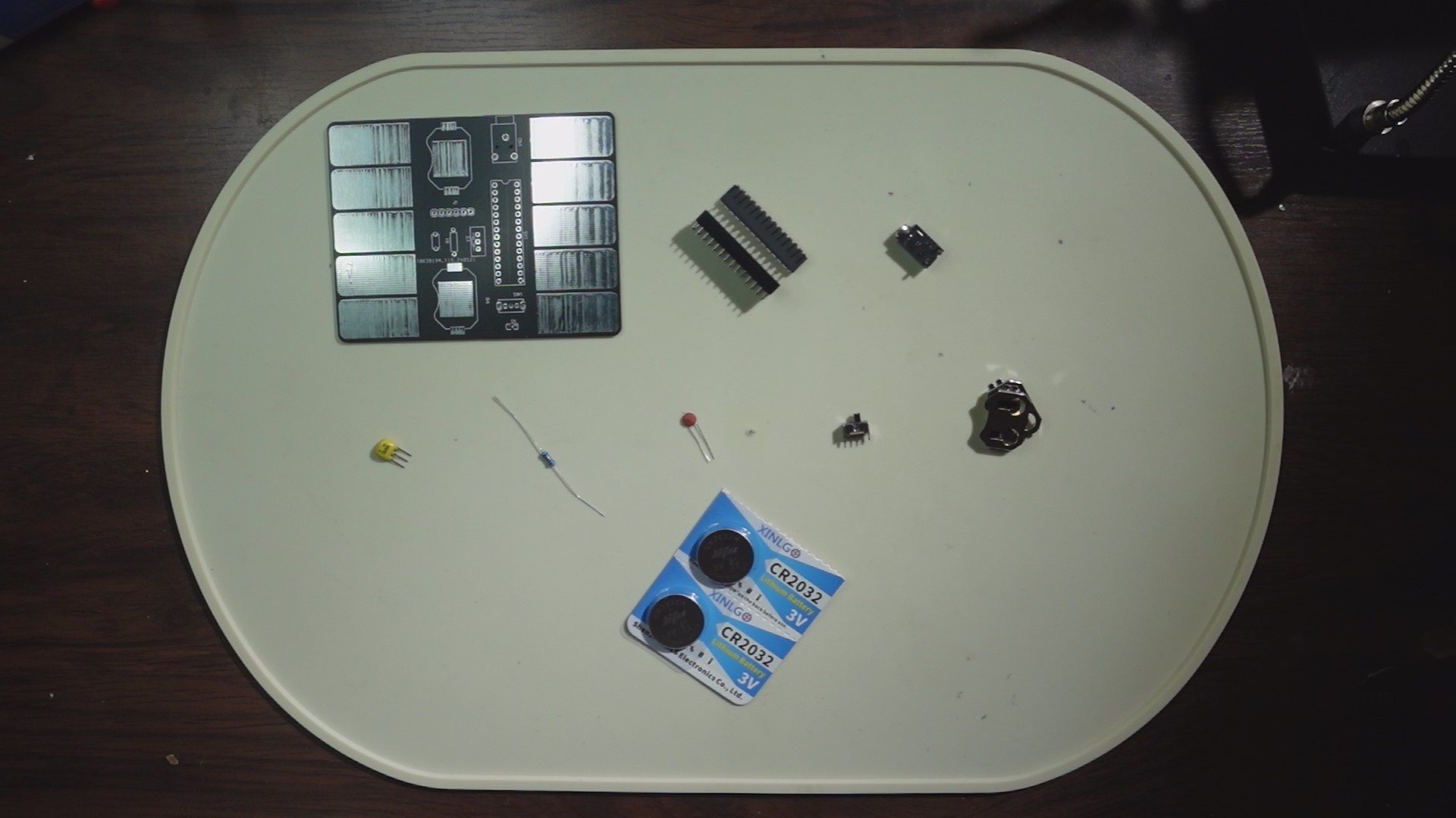
We'll prepare the necessary materials, including: One PCB board. (Scroll down to the PCB file below, enter the editor, and click "Place Order"—remember to use your free coupon!)
One Atmega 328P. (If you're purchasing, you can buy one with the bootloader already burned in, which will be more convenient for later use.)
One 28-pin connector. (For connecting the Atmega 328p)
One 3-pin headphone jack. (Model: PJ318)
One 16MHz crystal oscillator. (I used ZTT; if you want to use the same one, search for ZTT16MHz crystal oscillator.)
One 10kΩ through-hole resistor.
One 0.1uF through-hole ceramic capacitor.
One 3-pin 2-position toggle switch. (Vertical)
Two 2032 button battery holders. (Model: 2032-BK-912)
Two CR2032 button batteries. (3V)
One 0805 LED. (I used a green one.)
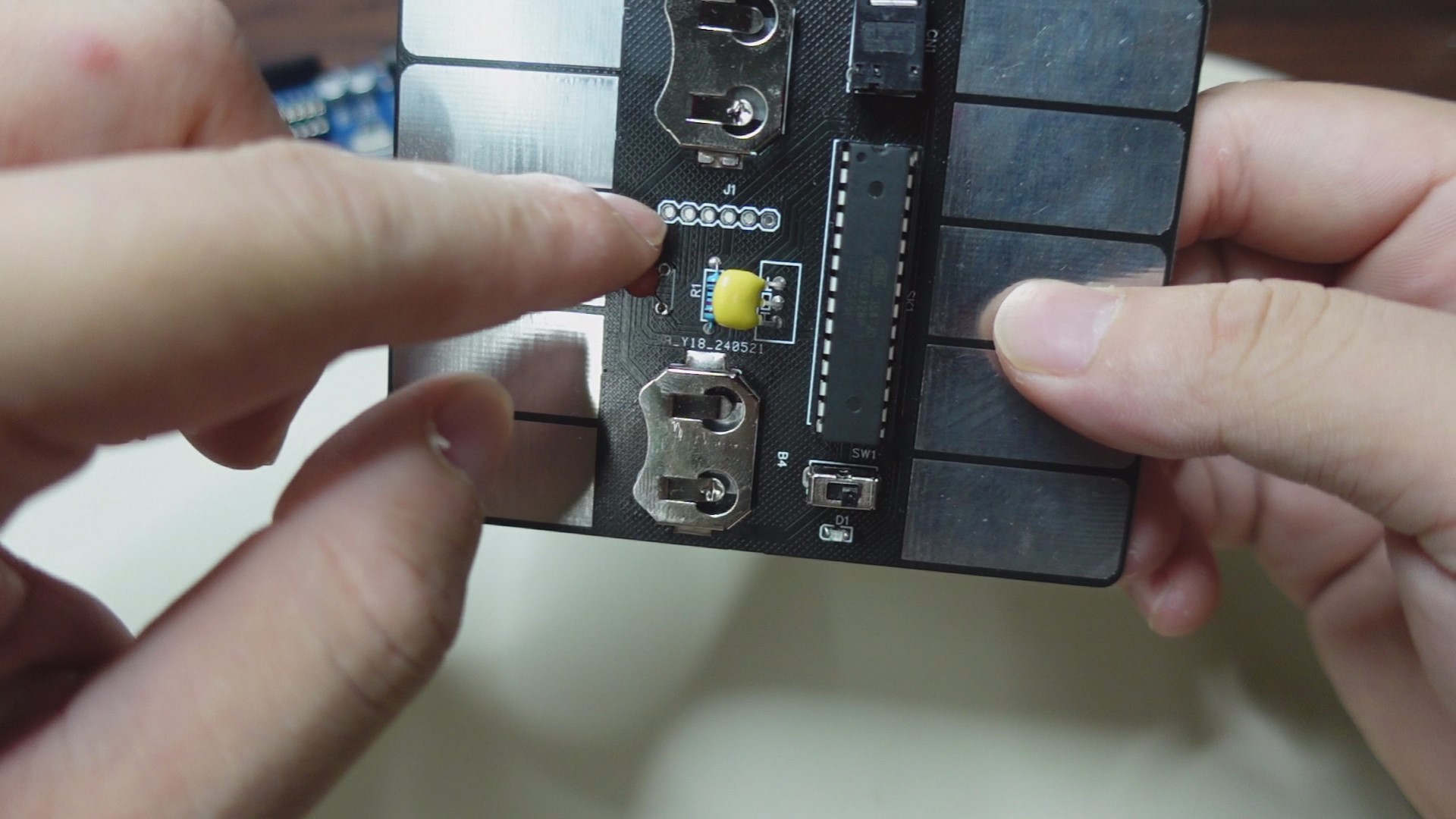
STEP 2:
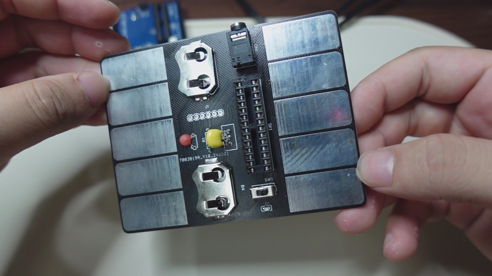
Assemble the components in place (refer to the markings in the circuit board file and the above diagram). Note that I did not protrude the pins from the back of the circuit board during installation, so that it can be laid flat for later use.
STEP 3:
Next, we'll upload the firmware code to the Atmega 238p controller. There are two methods:

As shown in the image above ↑↑↑
The first method, if you have an Arduino UNO, plug the 328p into the UNO's socket, connect the UNO to your PC, open the Arduino software, select the corresponding motherboard model, and download the firmware code from the attachment. After uploading, unplug the 328p and install it into the socket on your circuit board. (Note that the 328p's installation orientation corresponds to the notch on the socket).

As shown in the image above ↑↑↑
The second method doesn't require an Arduino UNO. Instead, use the UART interface on the circuit board. Plug the 328p into the socket on the circuit board, solder the header pins to the interface, and then use an FTDI cable to connect one end to the header pins and the other end to the PC. Again, open the Arduino software, download the firmware code from the attachment, select the corresponding motherboard model, and start the upload.
FINAL:
That concludes the entire production process. Let's turn on the switch and LET'S GO! ~(˘▾˘~) ~(˘▾˘)~ (~˘▾˘)~
video.mp4
card-stylophone.ino
pitches.h
PDF_DIY PCB Electronic Musical Instrument for 5 Yuan - Cardboard Electronic Keyboard! .zip
Altium_DIY PCB Electronic Musical Instrument for 5 Yuan - Cardboard Electronic Keyboard! .zip
PADS_DIY PCB Electronic Musical Instrument for 5 Yuan - Cardboard Electronic Keyboard! .zip
BOM_DIY PCB Electronic Musical Instrument - Cardboard Electronic Keyboard for 5 Yuan! .xlsx
94426
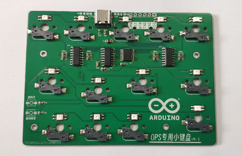
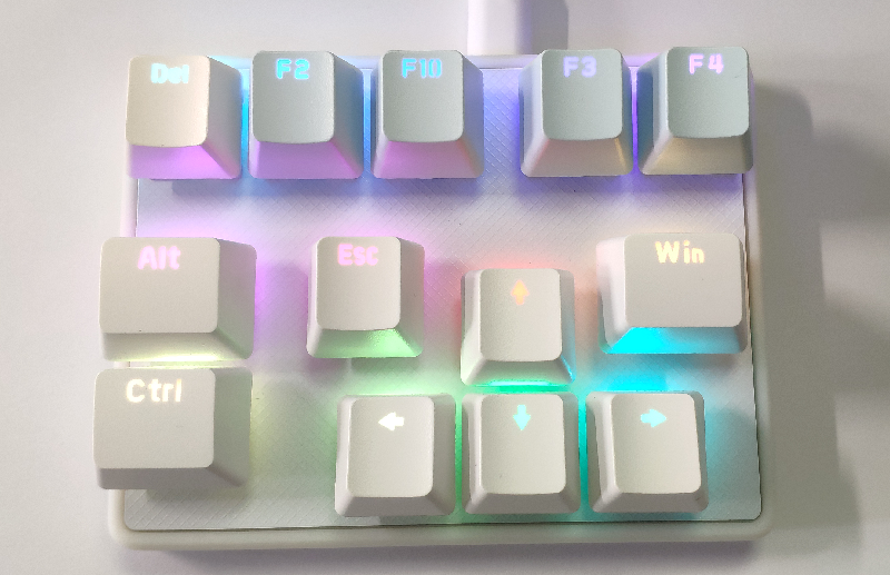
OPS dedicated numeric keypad
This is a keyboard for setting up the BIOS on an all-in-one PC's OPS (Optical Programming System).
The main controller is the Hezhou Air001, the firmware is developed using Arduino, key scanning uses Hanwen Keyboard's scanning solution, and HID interaction uses the Qinheng CH9329 chip.
Project Description: This project describes
a keyboard for setting up the BIOS on an all-in-one computer (OPS).
The main
controller is the Hezhou Air001, the firmware is developed using Arduino, key scanning uses Hanwen Keyboard's scanning solution, and HID interaction uses the Qinheng CH9329 chip.
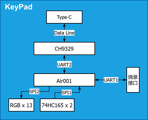
The main controller Air001
reserves UART1 as a firmware burning interface.
It communicates with the CH9329 chip via UART2, transmits and receives HID data
via SPI1 connected to the 74HC165 chip, obtains button status
via SPI2 to drive the reverse-mounted WS2812 LED bead, and adds RGB lighting effects.
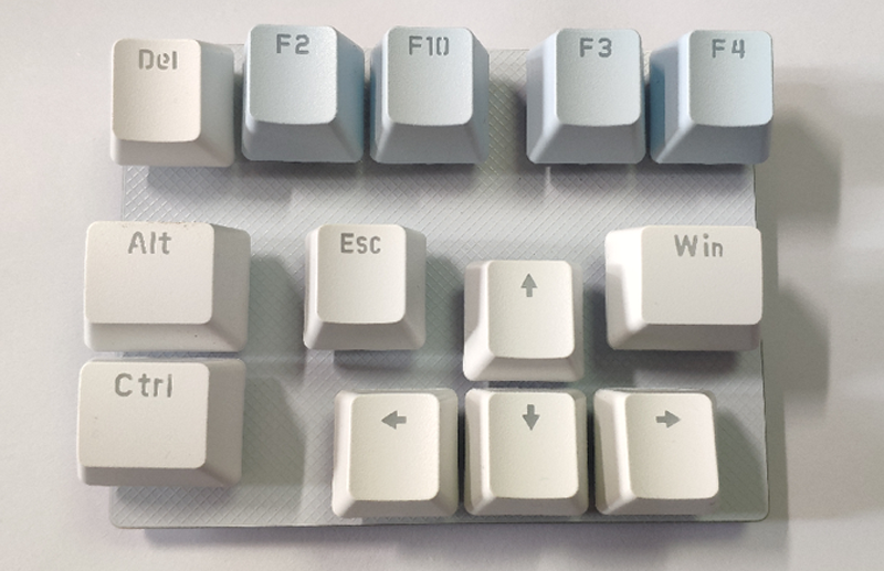
The button layout and functions
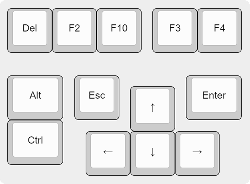
of the numeric keypad are shown in the table below:
Key
Function
Description
Del, F2, F10
Enter BIOS
for most machines
Ctrl + Alt + Del
Hot start
Arrow keys
move cursor
Enter
enter the next level of settings
or open settings details
Esc
return to the previous level of settings
or close settings details
F10
Exit and save settings
(requires Enter key confirmation)
Ctrl + F3
One-click backup function for some OPS
Ctrl + F4
One-click restore function for some OPS For
software instructions and firmware burning methods,
please refer to the documentation in the project "OPS Dedicated Numeric Keypad".
The numeric keypad has a reserved programming interface, which can be used with the Air001 auto-programmer to automatically download firmware,
or other serial port programming tools can be used for firmware download.
The physical demonstration shows
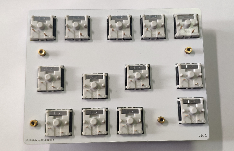

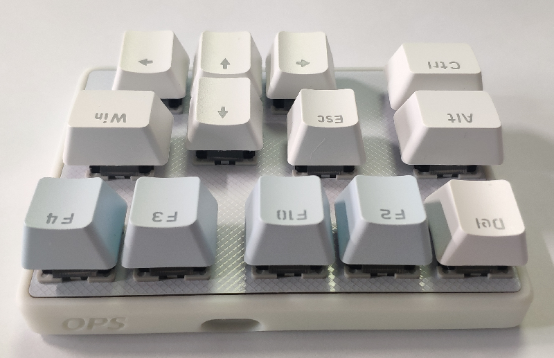


the component assembly. The
assembly order and materials are as follows:
Positioning plate * 1:
4 M2*3 injection molded copper double-ended nuts welded to the reverse side (knurled double-ended nuts are not used to increase the welding area);
Main control board * 1
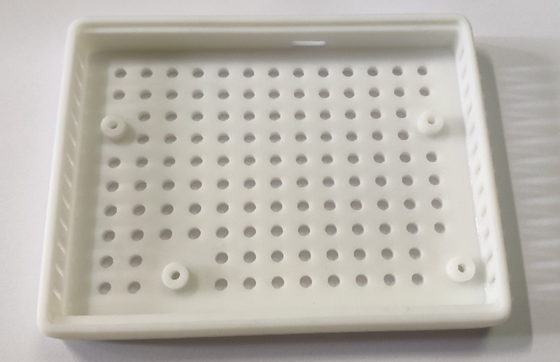
; Bottom shell * 1
(requires 4 M2*8 hex socket screws).
Reference project:
[Hanwen] HelloWord-Keyboard
OPS Numeric Keypad_Bottom Case.STL
PDF_OPS Dedicated Keyboard.zip
Altium_OPS Dedicated Numeric Keypad.zip
PADS_OPS Dedicated Numeric Keypad.zip
BOM_OPS Dedicated Numeric Keypad.xlsx
94427
electronic


 京公网安备 11010802033920号

 68002-536H


