QQ Group for Discussion: 571521559
This time, I'm sharing a new electronic musical instrument project:

• It's called "Card Stylophone" because its main body is a PCB board, looking just like a card, and it has similar gameplay to a stylophone.
• This project doesn't use complex analog circuits like 555 timers or oscillators; instead, it's all implemented through firmware code, significantly reducing the number of components that need to be soldered.
• To exaggerate a bit, Card Stylophone is a "minimum viable product," aiming to minimize the time from starting the kit to creating music with it.
Okay, let's start practicing the production steps and relive the 80s style of electronic music! :)
(Best enjoyed with the video below!)
↓↓↓
https://www.bilibili.com/video/BV1UJ4m137x1/
STEP 1:
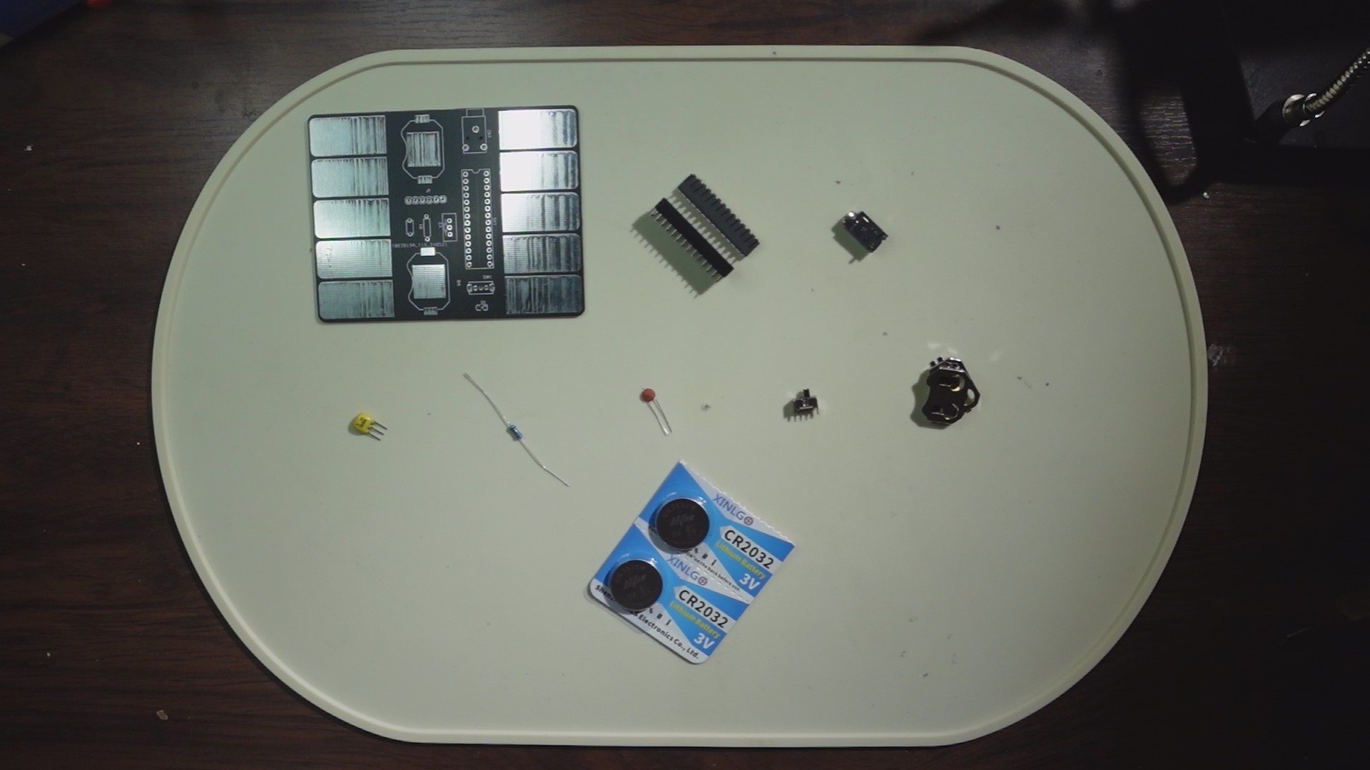
We'll prepare the necessary materials, including: One PCB board. (Scroll down to the PCB file below, enter the editor, and click "Place Order"—remember to use your free coupon!)
One Atmega 328P. (If you're purchasing, you can buy one with the bootloader already burned in, which will be more convenient for later use.)
One 28-pin connector. (For connecting the Atmega 328p)
One 3-pin headphone jack. (Model: PJ318)
One 16MHz crystal oscillator. (I used ZTT; if you want to use the same one, search for ZTT16MHz crystal oscillator.)
One 10kΩ through-hole resistor.
One 0.1uF through-hole ceramic capacitor.
One 3-pin 2-position toggle switch. (Vertical)
Two 2032 button battery holders. (Model: 2032-BK-912)
Two CR2032 button batteries. (3V)
One 0805 LED. (I used a green one.)
STEP 2:
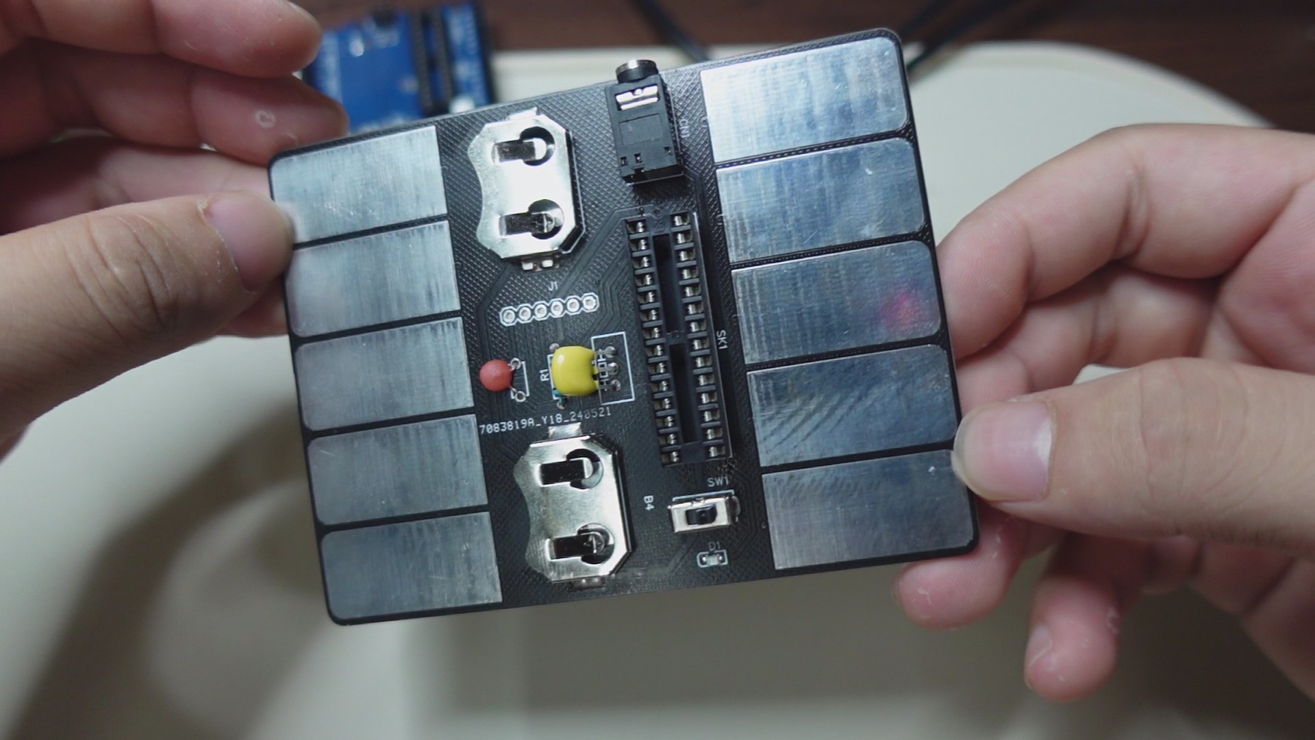
Assemble the components in place (refer to the markings in the circuit board file and the above diagram). Note that I did not protrude the pins from the back of the circuit board during installation, so that it can be laid flat for later use.
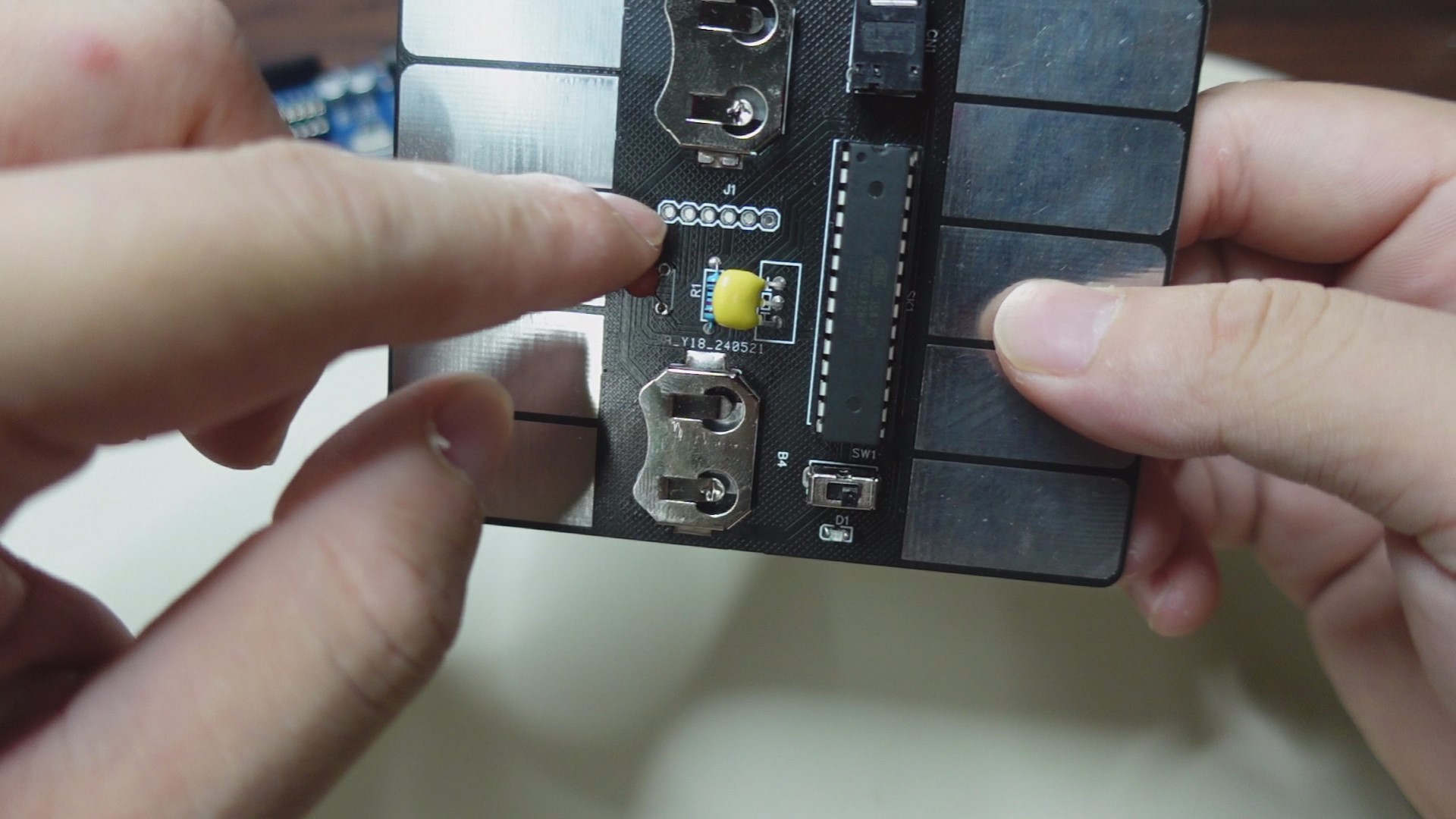
STEP 3:
Next, we'll upload the firmware code to the Atmega 238p controller. There are two methods:

As shown in the image above ↑↑↑
The first method, if you have an Arduino UNO, plug the 328p into the UNO's socket, connect the UNO to your PC, open the Arduino software, select the corresponding motherboard model, and download the firmware code from the attachment. After uploading, unplug the 328p and install it into the socket on your circuit board. (Note that the 328p's installation orientation corresponds to the notch on the socket).

As shown in the image above ↑↑↑
The second method doesn't require an Arduino UNO. Instead, use the UART interface on the circuit board. Plug the 328p into the socket on the circuit board, solder the header pins to the interface, and then use an FTDI cable to connect one end to the header pins and the other end to the PC. Again, open the Arduino software, download the firmware code from the attachment, select the corresponding motherboard model, and start the upload.
FINAL:
That concludes the entire production process. Let's turn on the switch and LET'S GO! ~(˘▾˘~) ~(˘▾˘)~ (~˘▾˘)~


 京公网安备 11010802033920号

 A-363SR


