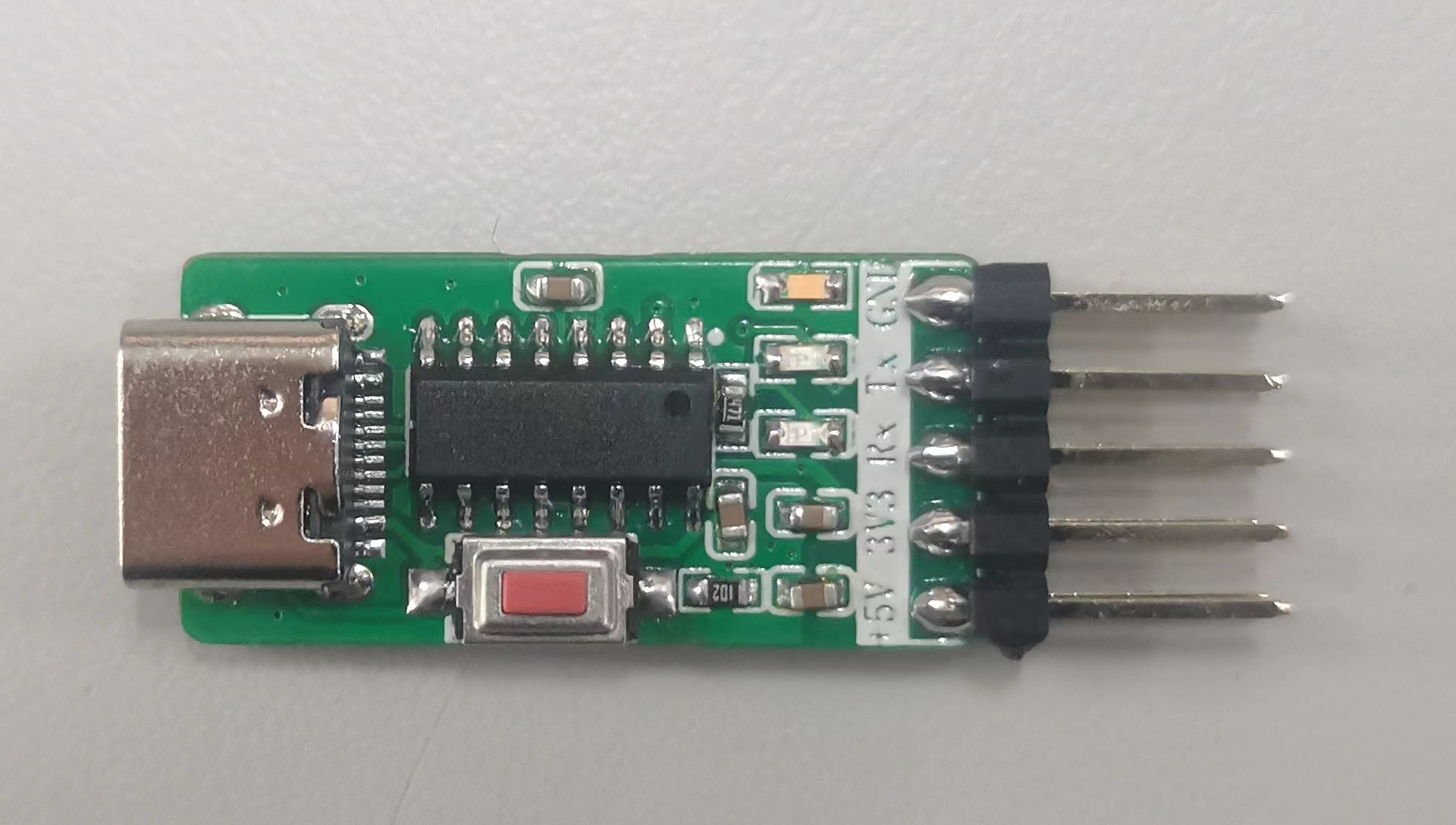
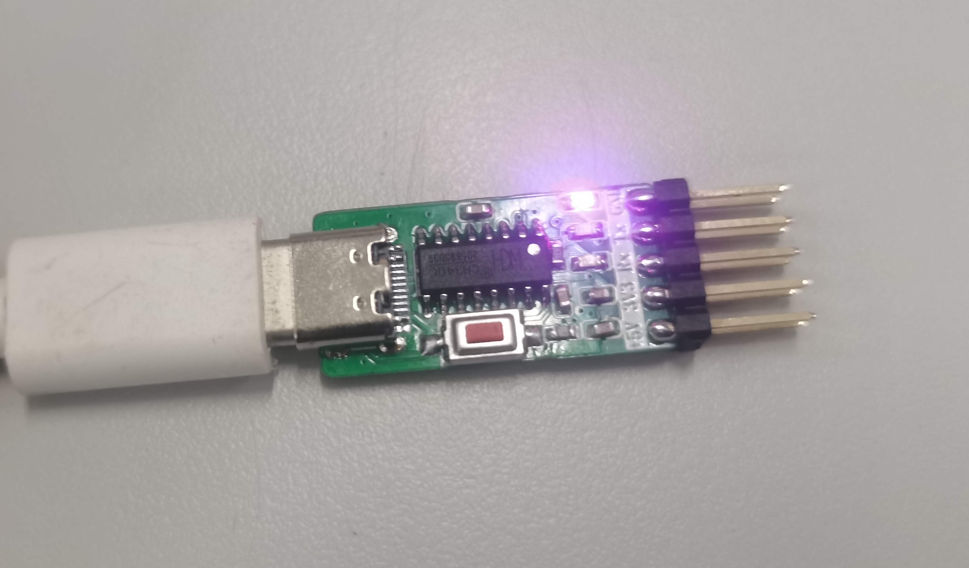
This USB-to-serial module based on the CH340C comes with built-in STC, STM32, and ESP32 serial download circuits, all of which have been successfully verified.
STC programming method:
Correctly connect power, GND, Tx, and Rx. In stc-isp, select the serial port, click "program," and press the button on the module. The microcontroller will power off and reset, then programming will begin.
STM32 programming method:
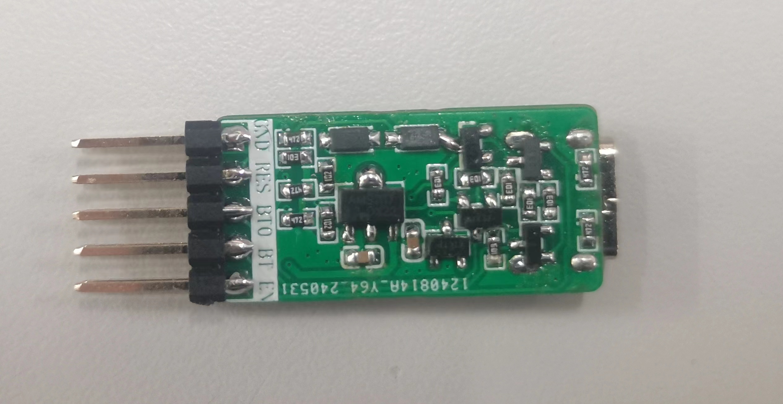
Correctly connect power, GND, Tx, and Rx. Connect RES to the microcontroller's reset pin and BT0 to the microcontroller's Boot0 pin. In FlyMCU, select DTR (low level reset) and RTS (high level bootloader). Select the serial port, click "program," and begin programming.
ESP32 programming method:
Correctly connect power, GND, Tx, and Rx. Connect EN to the microcontroller's reset pin and BT to the microcontroller's Boot pin. Program according to the appropriate programming method.
PDF_USB to Serial Port Module.zip
Altium_USB to Serial Port Module.zip
PADS_USB to Serial Port Module.zip
BOM_USB to Serial Port Module.xlsx
94447
Cool Summer Dinosaur Game
This DIY dinosaur game console is a retro-modern entertainment marvel that makes your leisure time lively and fun. It's a refreshing summer entertainment companion, bringing a cool touch to your hot summer days with its unique summery style.
This little dinosaur game console is technically called "Dino Game Design Based on Capacitive Detection and Control" ( ̄▽ ̄)"
1. Basic Introduction
: It uses the classic STM32C8T6 as the main controller, adding peripherals such as TIM, IIC, DMA, and USART. It imports OLED driver libraries and font library to implement the little dinosaur game console functions. (Many thanks to kk for providing the game library!)
Touching the copper plates makes the dinosaur jump, and changing the spacing of the external copper plates changes the capacitance, thus altering the game difficulty.
It also features a 3D-printed ice-white shell, further enhancing the summery feel O(∩_∩)O
2. Software design and implementation mainly include game interface design, game logic implementation, data communication protocol formulation, and hardware/software co-debugging.

The functions shown above are the most basic functions of the Little Dinosaur game,
with the following functions: setting the initial interface, displaying the image on the OLED, changing the dinosaur's state, randomly generating obstacles, displaying the score in real time, and calling these functions as the main function.
3. Hardware design and implementation mainly involve capacitive touch buttons and capacitive adjustment of game difficulty.
The capacitive touch buttons are implemented using a capacitor-to-frequency converter + frequency-to-voltage converter + comparator. The frequency measurement is achieved using a separate capacitor-to-frequency circuit.
Touching the copper plates makes the dinosaur jump, and changing the spacing of the external copper plates changes the capacitance, thus changing the game difficulty.
Furthermore, compared to ordinary buttons, capacitive buttons prevent accidental touches (one hand must touch the ground copper plate while the other hand touches the control copper plate to complete an effective action).
4. In summary,
this little dinosaur game console not only boasts exquisite graphics and smooth animation effects but also incorporates various interactive elements. Players can control the dinosaurs with simple operations to complete various tasks, unlock new levels and rewards. The game features a wide variety of dinosaurs, each with its own unique skills and characteristics, waiting to be discovered.
This homemade little dinosaur game console is more than just a game machine; it's a refreshing summer entertainment companion. With its unique summer style, it brings a cool entertainment experience to your hot summer days, allowing you to enjoy the fun of the game while also feeling the beauty of summer. Let's cool off this summer together and embark on this fantastic summer journey!
VID_20240522_000816.mp4
1.jpg
2.jpg
3.jpg
Dino daima.rar
PDF_Cool Summer Little Dinosaur Game.zip
Altium_Cool Summer Little Dinosaur Game.zip
PADS_Cool Summer Little Dinosaur Game.zip
BOM_Cool Summer Little Dinosaur Game.xlsx
94451
ESP32S3_PX4 small aircraft
Small aircraft using ESP32S3 based on PX4 firmware
This is a small drone based on PX4 firmware using the ESP32S3. The hardware design comes from https://github.com/espressif/esp-drone, and the firmware will be released at https://github.com/w2016561536/PX4-Autopilot/tree/px4_esp32s3. Hovering, automatic landing, and some manually controlled flights have been tested.
Precautions:
1. Do not arbitrarily increase the cycle frequency; the ESP32S3 has limited capabilities.
2. Someone must supervise the charging process!!! This is crucial! Someone must supervise the process!!! Remove any flammable materials nearby. The charging circuit has not undergone rigorous testing, and its stability cannot be guaranteed (especially for DIY projects).
3. Non-professionals should not connect the 0-ohm resistor next to IP5109 (this indicates a hardware problem), otherwise it may cause timing errors or even sensor damage!!
7. If the external sensor is powered by 3.3V, it is recommended to use a jumper wire from the capacitor near the ESP32S3, not from the SENSOR_3V3.
5. Due to insufficient space for a 5.1K resistor, C-to-C data cables are not supported.
6. Please abide by laws and regulations during flight and do not fly beyond visual line of sight.
7. Configured Wi-Fi SSID: MY_PX4 Password: 12345678
8. In the motor configuration, remember to change the output mode to oneshot, set the throttle disarm value to 0, the minimum value to 100, and the maximum value to 2000-2100; otherwise, the motor will restart upon pushing the throttle.
9. If severe IMU drift occurs, please reinsert the battery without connecting it to the USB power supply (the reason is BOOST ripple noise during takeoff).
10. I am using a 720 motor with a protective coil for fixation. An 8250 motor can be used, but a custom fixture design is required.
11. For optical flow, refer to https://item.taobao.com/item.htm?abbucket=6&id=660420384217&ns=1&spm=a21n57.1.0.0.f58f523cFcFVbE&sku_properties=1627207:21549958229. The protocol must be the same. DIY is possible. The corresponding driver is flow3953. The SENS_NKFLOW_CFG parameter controls the port used.
12. The bracket can be the one included in PCB1 (you need to cut it yourself) or 3D printed (see attached STL model).
13. If you need to use a joystick or virtual controller for flight in QGC instead of a remote controller, you still need to set the relevant parameters for the remote controller; otherwise, unlocking will be refused.
14. The aircraft supports SBUS remote control. To use it, connect the SBUS cable to UART2 RX and modify RC_PORT_CONFIG to Radio Controller and UART2_RX_INV to Enable in the parameter table.
15. The charging current of the IP5109 is configurable; the parameter is BAT_CHG_CURRENT, in milliamperes (mA).
16. Program Flashing: Go to the firmware release page: https://github.com/w2016561536/PX4-Autopilot/releases, download bootloader.bin, partition-table.bin, and px4_esp32s3_default.bin from the latest release. Then download the Espressif flashing tool: https://www.espressif.com.cn/sites/default/files/tools/flash_download_tool_3.9.5_0.zip. Place all files in a folder (the path cannot contain Chinese characters). Then, hold down Shift, right-click in the folder, and open PowerShell. Connect the device to the flight controller using a USB cable and execute `esptool.exe -p write_flash 0x0 bootloader.bin 0x10000 px4_esp32s3_default.bin 0x8000 partition-table.bin`. Replace `partition-table.bin` with the flight controller's serial port number. Press Enter and wait for the flashing process to complete.
17. If the PCB1 reviewer approves the panelization, proceed to PCB1_1. The only difference is that PCB1_1 lacks a stand, requiring you to make your own (e.g., 3D printing; STL is attached).
18. PCB2 is a self-made serial port tool, easily connecting to the aircraft's serial port; make as needed.
Current issues:
1. PX4 cannot read IP5109 voltage data via the I2C bus due to power-on timing (TLV75733 output is later than IP5109's pin mode judgment). The solution is to use jumper wires (allowing IP5109 to exclusively use I2C2, and modifying the pull-up power supply from IP5109's built-in LDO).
2. I2C2 is currently disabled; it may be used by IP5109 later if needed.
3. Some functions are not implemented: IMU heating, indicator lights (except for power indicator). Therefore, components for IMU heating, colored indicator lights, and I2C2 sockets do not need to be purchased.
3. Unable to use MTF optical flow (or other sensors using MAVLINK with very high feedback frequencies), it's too laggy. (I wrote a driver for optical flow based on VL53L1X and PMW3901 from Taobao, and it seems pretty good.)
4. USB is unstable due to buffer issues; therefore, the USB interface can only be used for programming and charging.
VID_20240317_184644.mp4
VID_20240317_184806.mp4
Small airplane bracket.stl
PDF_ESP32S3_PX4 small aircraft.zip
Altium_ESP32S3_PX4 small aircraft.zip
PADS_ESP32S3_PX4 small aircraft.zip
BOM_ESP32S3_PX4 Small Aircraft.xlsx
94452
Compact step-down module
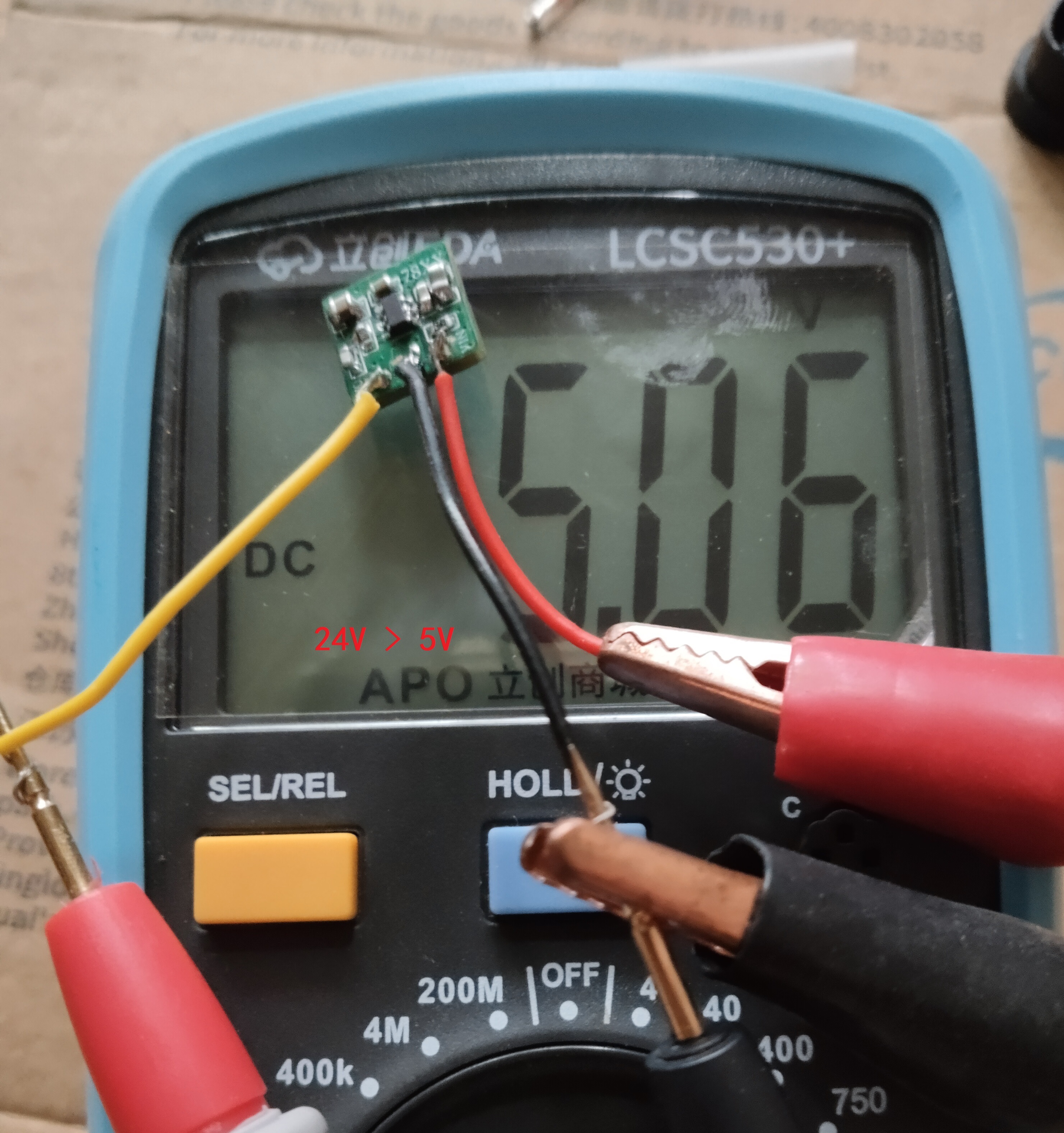
The compact step-down module measures 11mm x 11mm.
This compact step-down module measures 11mm x 11mm, similar to the K7805. It converts 12V/24V to 5V input and works with an LDO. The chip is in an SOT-23-6 package and can be replaced with other chips of the same package type to increase load capacity. Other options include LMR14010, AOZ1282, MP2456, and TPS560430 (synchronous). The module has a compact layout and presents some soldering challenges.
PDF_Small Step-Down Module.zip
Altium - Compact Step-Down Module.zip
PADS_Compact Step-Down Module.zip
BOM_Compact Step-Down Module.xlsx
94453
LTC7820 open source
LTC7820 boost charge pump
Except for capacitors and MOSFETs, materials can be purchased directly from the BOM.
1. Maximum support is 38V input and 76V output; do not exceed the voltage limit.
2. Please use 100V withstand voltage MLCCs. Large single-cell electrolytic capacitors, solid-state capacitors, and tantalum capacitors are not allowed for 4A input and output; MLCCs are required
. 3. The project's maximum allowable output is 35V. For other voltages, high-voltage capacitors must be used.
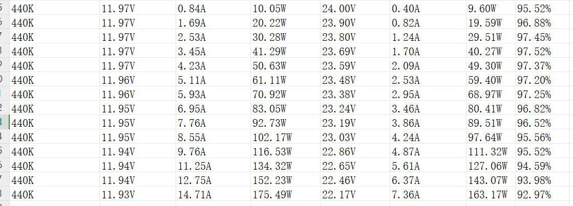
The following are my measured data for reference only;
these are general parameters.
Switch MOSFET model: BSC050N04LS;
Input protection MOSFET model: NXP1C030L;
Capacitor: So-called X7R 50V 10UF MLCC from Taobao (capacitor temperature 98°C at 160W output).
7820fc (1)_240315_114215.pdf
PDF_ltc7820 open source.zip
Altium_ltc7820 open source.zip
PADS_ltc7820 open source.zip
BOM_ltc7820 open source.xlsx
94454
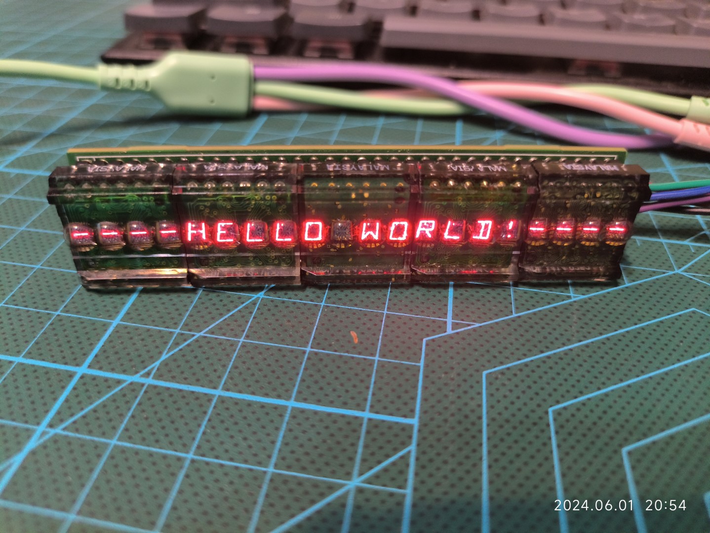
HPDL1414x5 Display Module (20 characters, SPI compatible)
A 20-character (5 HPDL-1414) display module, SPI compatible.
Three data lines drive a 20-character (5 HPDL-1414) display module, compatible with the SPI protocol. More information about this project can be found at [20-character (HPDL-1414*5) display module (serial protocol, SPI compatible)](https://hadongzhu.com/archives/711). The driver is open-source on Github (https://github.com/hadongzhu/HPDL1414x5_Driver).
![IMG_20240601_205413 (large).jpg]
PDF_HPDL1414x5 Display Module (20 Characters, SPI Compatible).zip
Altium_HPDL1414x5 Display Module (20 Characters, SPI Compatible).zip
PADS_HPDL1414x5 Display Module (20 Characters, SPI Compatible).zip
BOM_HPDL1414x5 Display Module (20 Characters, SPI Compatible).xlsx
94455
Portable mini fan with three speed settings
Portable fan with 3 adjustable fan speeds and powered by a single 18650 motor.
This project is a portable fan powered by an 18650, integrating lithium battery charging management and protection, and featuring 3 adjustable fan speeds. It is a pure hardware design.
Brief functions include:
0.6A lithium battery charging,
9V motor drive control, 3 adjustable fan speeds (5.4V for speed 1, 7.3V for speed 2, and 9.2V for speed 3),
a single-button switch for
charging and a full charge indicator
light, and a fan operation indicator light
. Note: When a charger is connected, a short press of SW1 will keep the fan operating at speed 1, with the fan light and charging light illuminated.
To ensure the charging current can properly supply the fan's rotation during charging, the fan will only operate at speed 1. SW1 will then function as a switch instead of a speed switch; it will only control the fan's on/off state during charging and cannot be used for speed switching. Regardless of the operating speed, connecting to a charger will automatically switch the fan to speed 1, and the fan will return to speed 1 after charging is removed.
BOM (Blow-out version):
CM3*16 x4 (for fixing the fan and housing)
M2*3 x4 (for fixing the PCB)
M2*2*3.5 thermosetting nuts x4 (for fixing the PCB)
18650 lithium battery x1
6015 fan x1 (I used a 5V fan; please test other models yourself)
PCB x1
Housing x1 set
If you find the front monotonous, you can attach a panel to it
for testing. The silent fan's airflow is average, while the non-silent one is quite noisy, and the airflow isn't particularly strong. Therefore, it's currently used as a welding smoke extraction fan.
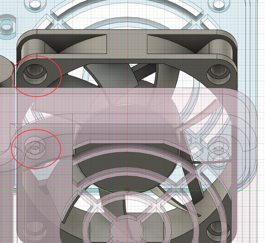
Actual product image
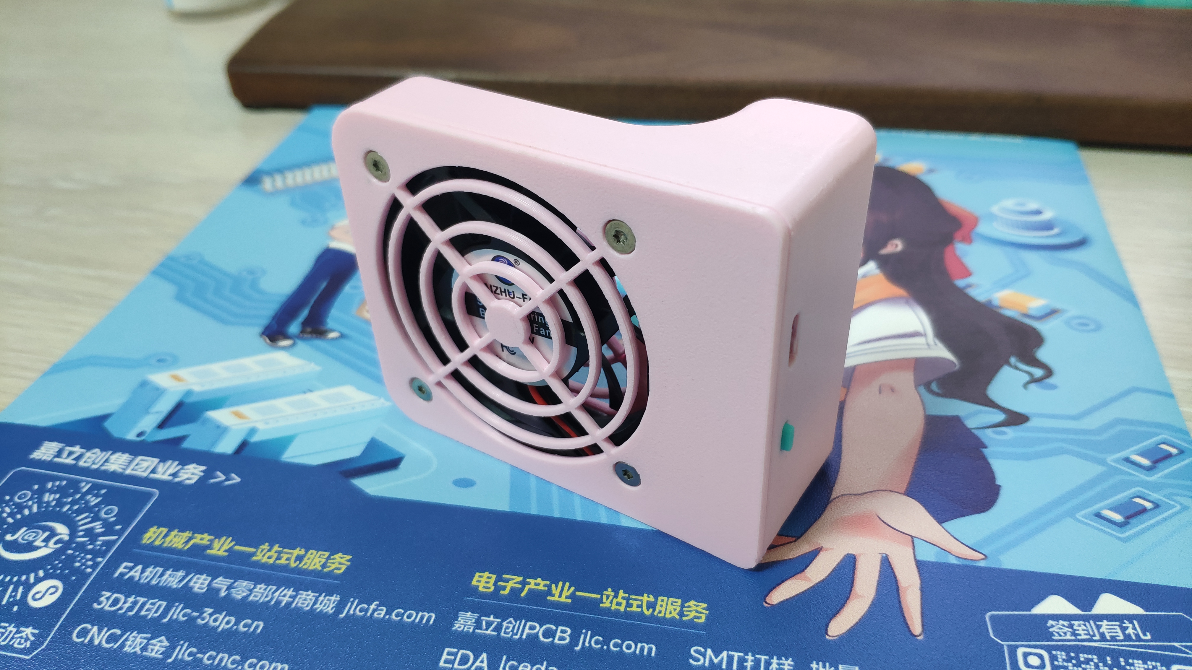
and assembly diagram .
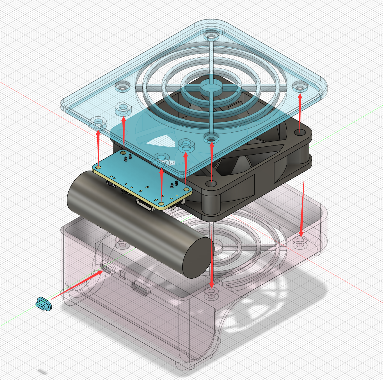
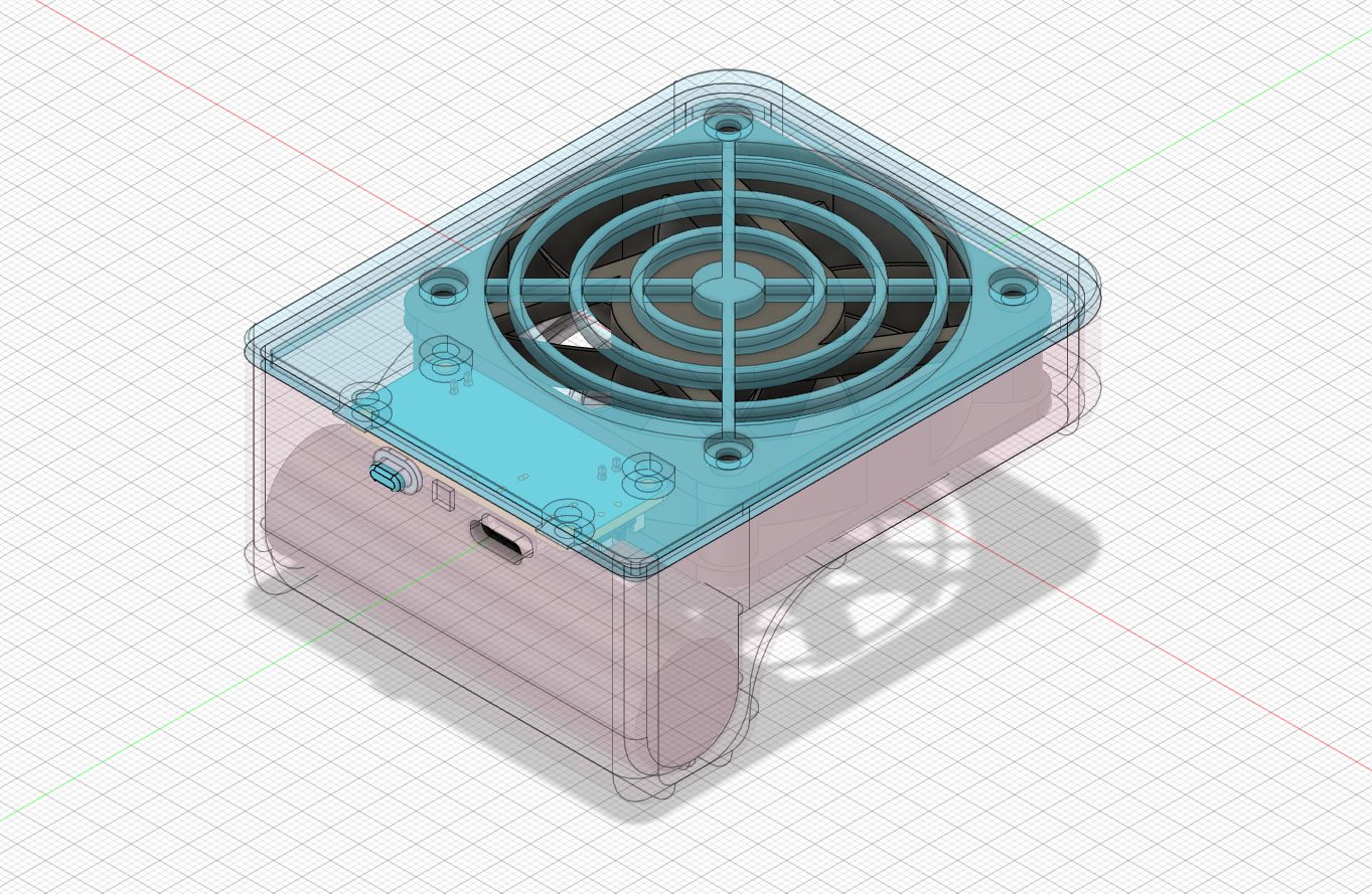
Note: The grooves at the screw holes below the fan correspond to the protrusions on the housing for installation (as shown in the picture).
VID_20240528_145620.mp4
faceshell.stl
bottom shell .stl
button.stl
Bottom shell (integrated button version, not yet verified).stl
PDF_Three-speed adjustable portable fan.zip
Altium_Three-speed adjustable portable mini fan.zip
PADS_Three-speed adjustable portable mini fan.zip
BOM_Three-speed adjustable portable mini fan.xlsx
94456
RGB heart-shaped flowing light
RGB heart-shaped flowing light
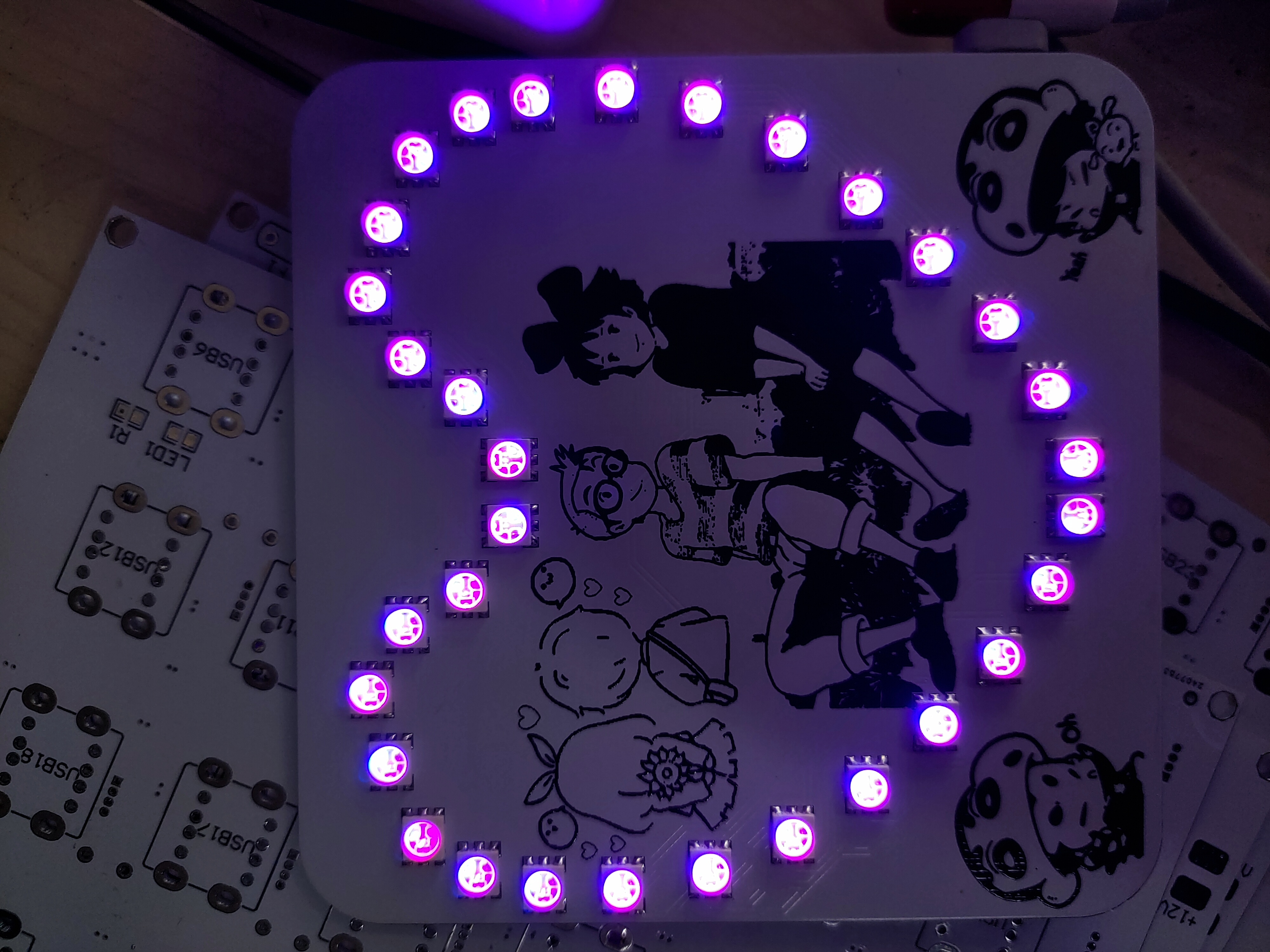
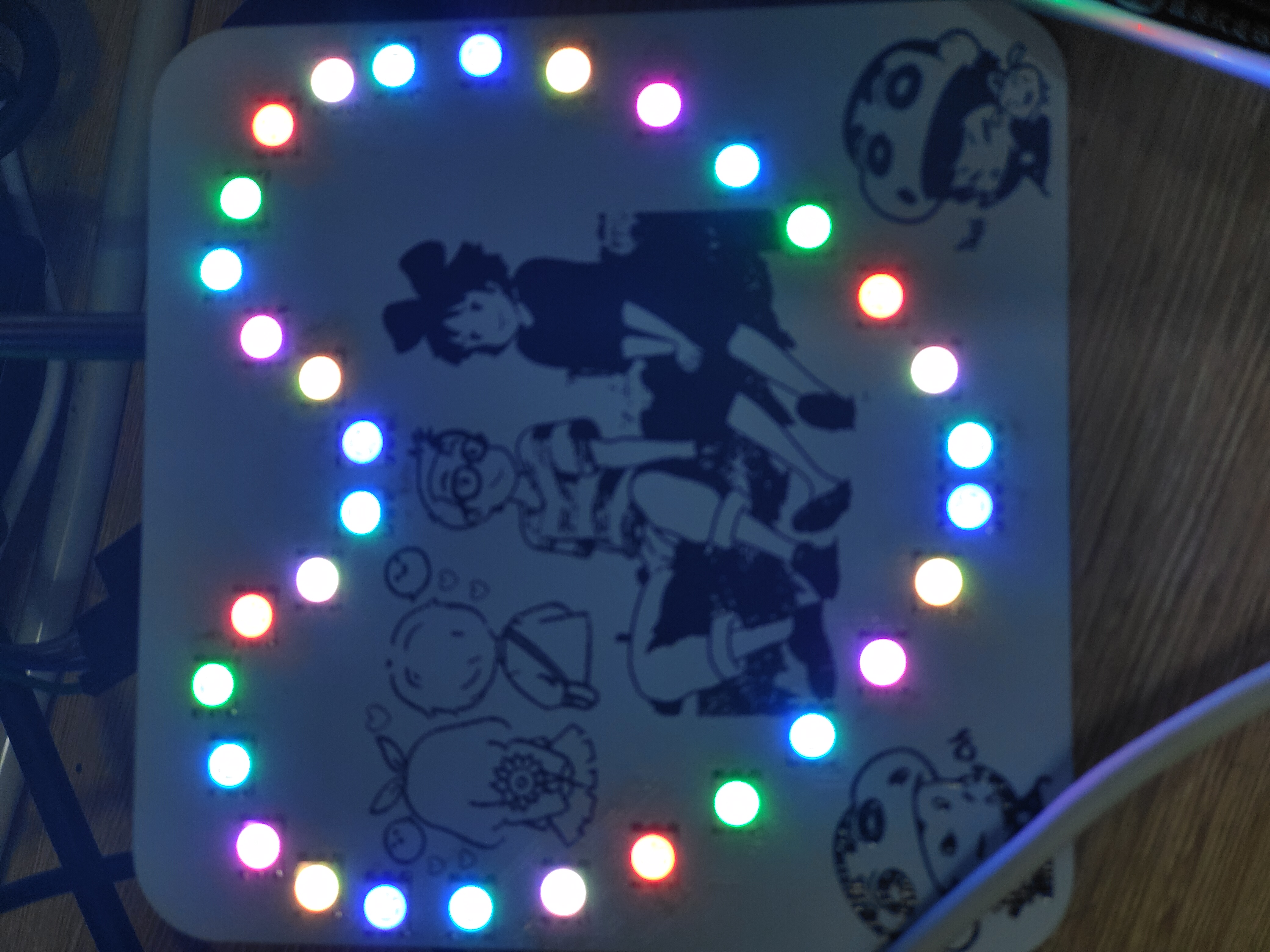
The 3D effect demonstration

is rather brief, please forgive the limited detail!
Soldering Precautions:
This document mainly focuses on surface-mount components, and the LEDs are machine-mount packages, making manual soldering somewhat difficult.
The Type-C interface uses a 6-pin through-hole package; the leads need to be flattened during soldering. The power switch also uses a 6-pin through-hole package, which also requires flattening before soldering!
Since there is no pre-installed download interface or download circuit on the board, downloading is also somewhat difficult and requires jumper wires.
Component Purchase Recommendation : For
RGB LEDs, you can use this link: https://item.taobao.com/item.htm?_u=23p15f8t0489&id=590715849209&spm=a1z09.2.0.0.67002e8deIJSIH&skuId=4222664047588
14.hex
PDF_RGB Heart-Shaped Flowing Lights.zip
Altium_RGB Heart-Shaped Flowing Light.zip
PADS_RGB Heart-Shaped Flowing Light.zip
BOM_RGB Heart-Shaped Flowing Light.xlsx
94457
electronic


 京公网安备 11010802033920号

 REC3-1212SRW/H6


